28th January 2025
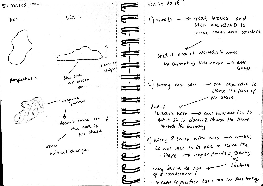
To begin making, I needed to find out how I could make the shapes I wanted in CAD. These shapes were taking inspiration from the shapes of bacteria grown, with the denser growths having more height. I initially tried this in Fusion360, as I find it to be more user-friendly, however, I could not find exactly what I wanted there, so I moved back to Rhino8. In Rhino, I began experimenting with various tools I found through both the Rhino website and YouTube. Through this research, I identified three potential methods to execute my idea. Although I wasn’t sure how they would work, I figured the best approach was to experiment, see the results firsthand, and go from there.
1. ToSubD
The first tool I experimented with was ToSubD. I followed a YouTube tutorial to understand the basics, but unfortunately, it didn’t work as expected. While there was definitely some user error, I wasn’t sure exactly what I was doing wrong. My idea was that ToSubD would help me achieve the smooth surface I wanted, which I could then split and cap to create the flat back. I knew this method would require extra steps, but it seemed like a logical approach in my mind.
When this attempt didn’t work, I decided to try a slightly different approach.
Edit: I showed the problem to Geoff who had a look at the settings for me. He found that the command bar didn't show the options for changing the input which is why it did not work. Instead, I would have to continue using SubDivide to round out the shape. This still didn't give me the shape I wanted, however, I now know what the problem was and how to overcome it.
2. Cage Edit
For my second attempt, I tried using the Cage Edit tool. I was struggling to figure out how to design the shape I wanted, and as a hands-on maker, I’m so used to physically shaping things with my hands. Ideally, I wanted to be able to simply drag the shapes into place, similar to what I have previously done in Blender. I discovered that the Cage Edit tool allowed for this kind of manipulation, so I started by drawing a rough shape and then used Cage Edit to adjust its height.
In theory, this approach seemed promising, but in practice, it didn’t work as expected. I hadn’t considered that the entire shape, including the underside, would also be affected when using the tool. While this method wasn’t successful, it did help me gain a clearer understanding of the forms I wanted to create, which was still a useful takeaway.
3. Sweep 2
x20 speed
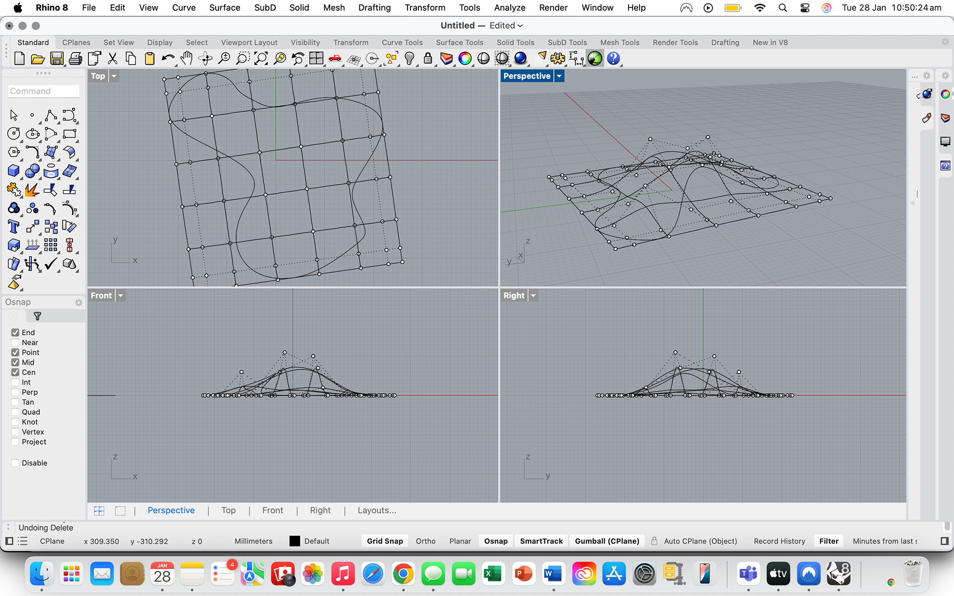
The 3rd tool I used was the Sweep2 tool. While this was the most ambitious of the 3 tools I was testing, I still gave it a go. I watched a YouTube tutorial before to try and understand how the tool worked. When I had a very basic understanding of it, I moved into Rhino to try it for myself. I first started by drawing a rough shape and then adding arcs with various heights to help achieve the smooth finish that I wanted.
It took a while to get used to the tool because it did not work exactly like I wanted it to. After speaking to Geoff, he then told me why, which I explain further down.
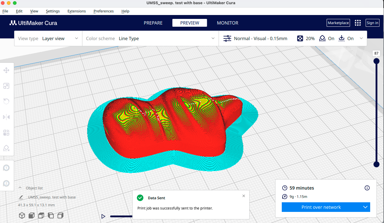
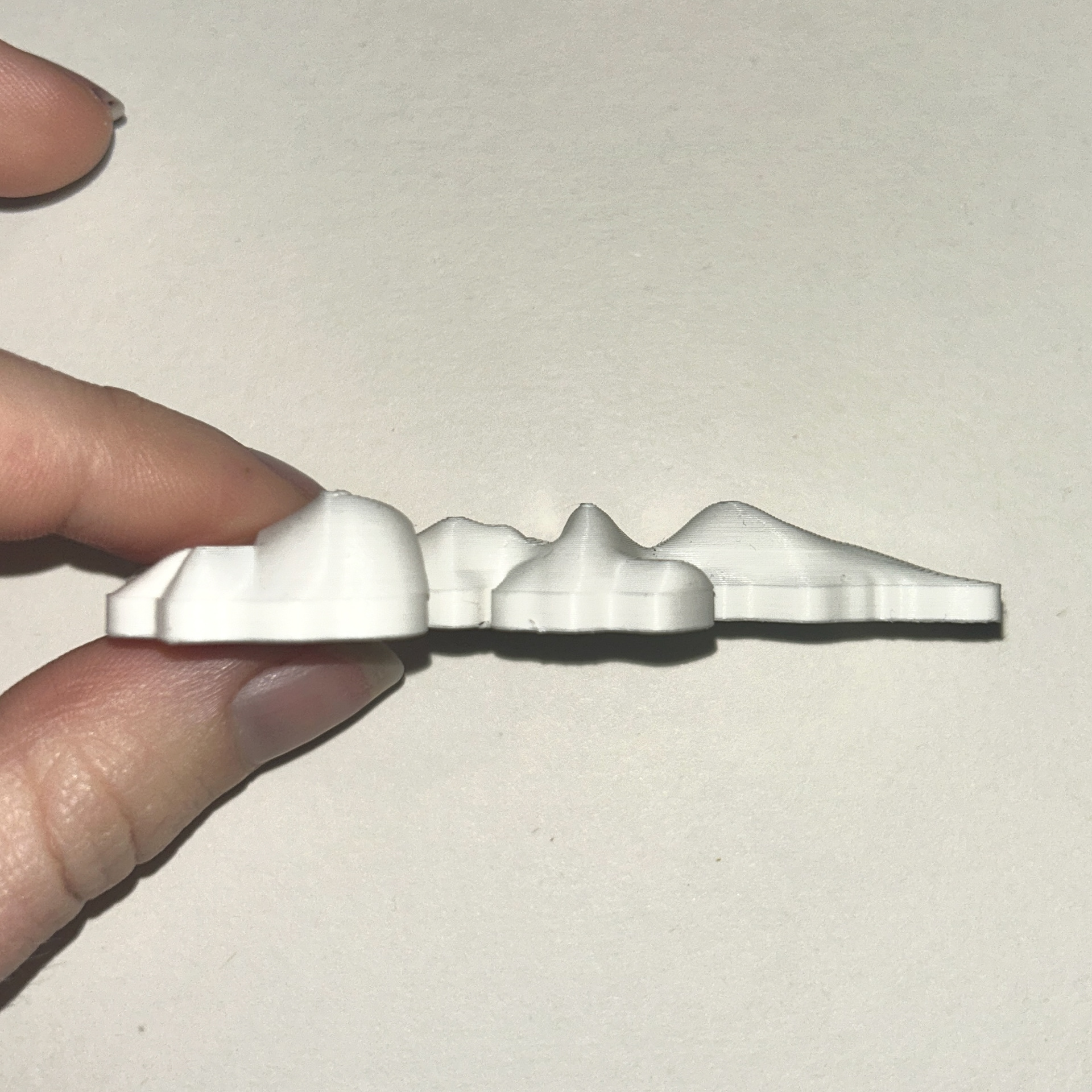
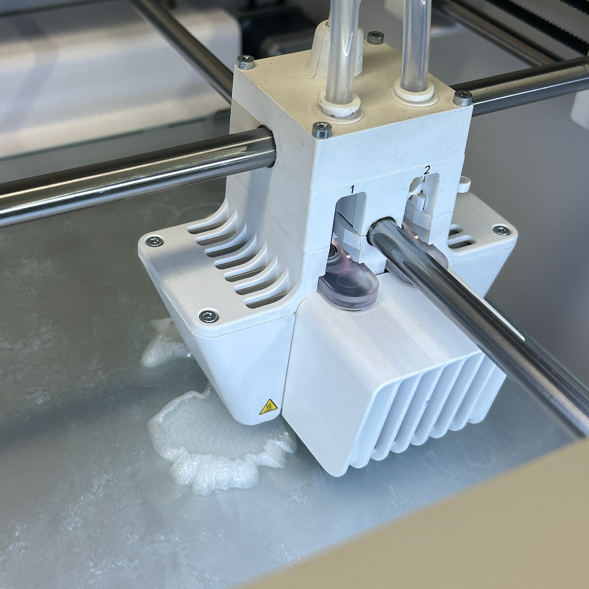
I then made another shape using the same method and sent it for printing to see how it looked. I decided to add a 3mm base as this would give me room to add a silver bezel around the shape, which at the time I was intending to do so I would be able to mount a brooch pin on the back. I knew I wanted to continue working in silver as this is hopefully what I will be using when I graduate, and I also enjoyed using silver during Unit X.
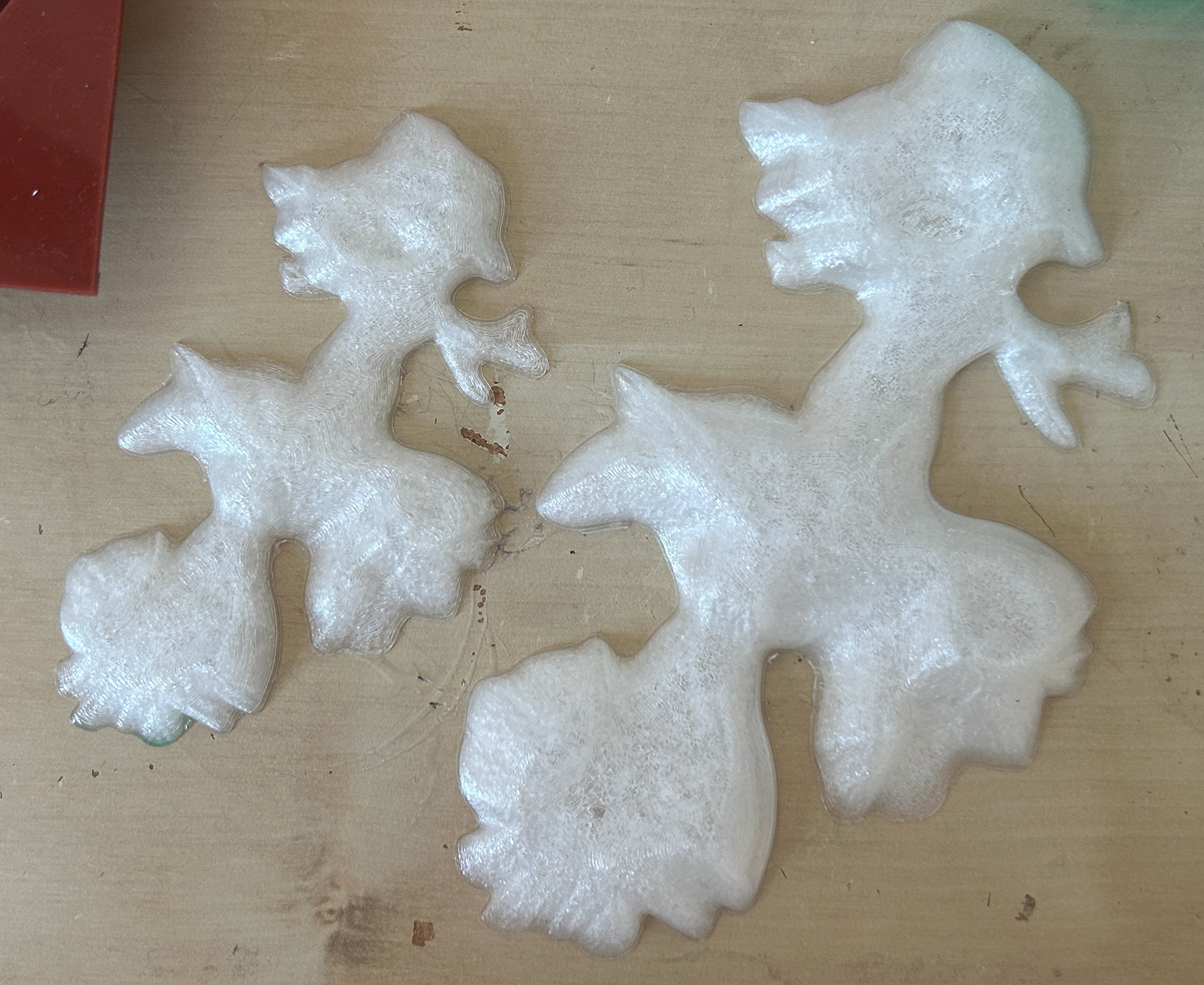
Although I was pleased to have started to figure out the shape of my designs, it was clear that significant refinement was still needed. I was satisfied with the height, but the edges of the curves appeared blocky rather than the smooth finish I wanted. While I knew I could sand them down to achieve the smoothness I wanted, this would require additional time to perfect the object. Additionally, I realised that relying solely on arcs for height, while it was effective in adding the dimension I wanted, did not create the level of complexity I was aiming for. With this in mind, I transitioned to a more intricate design, incorporating custom curves across the piece to use with the Sweep2 tool. This would hopefully make the piece more defined in the areas where the bacterial growth was denser.
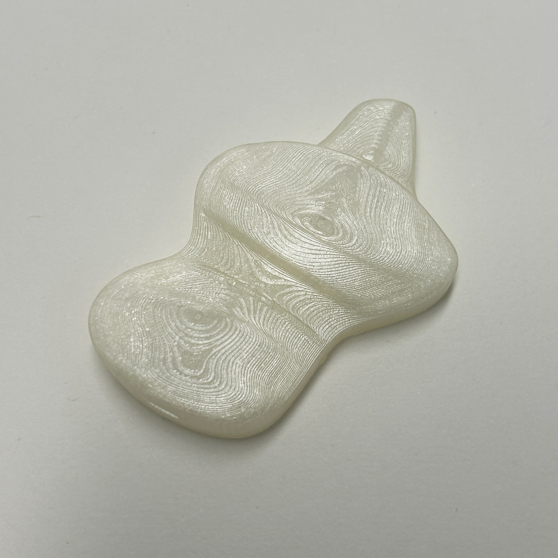
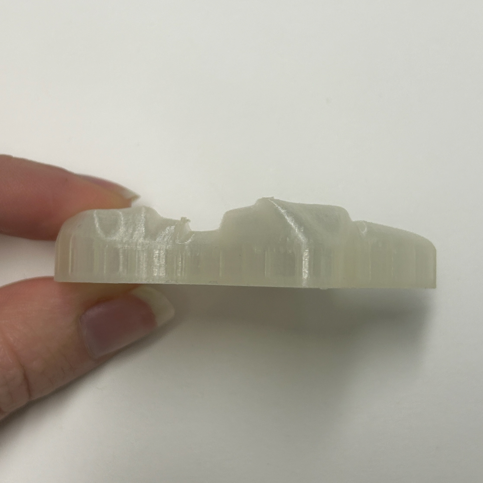
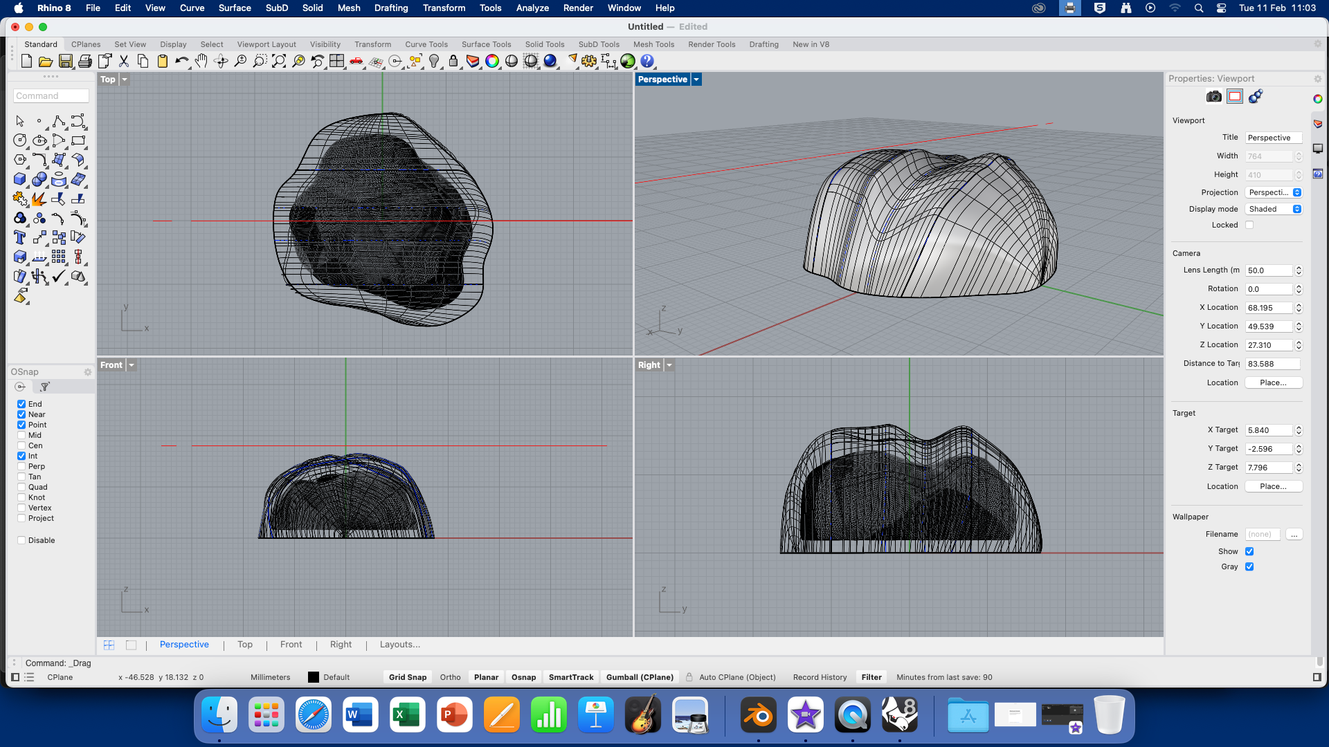
Building on what I had learned from my previous print, I returned to Rhino and focused on creating a shape that incorporated custom curves for the height. This allowed me to have greater control over the form, enabling me to pinpoint specific areas where I wanted the elevation to be higher or lower. By using custom curves instead of the simple arches I had previously relied on, I was able to achieve a more dynamic and organic shape. I found this method to be much more effective in adding depth and complexity to the design, making the overall structure more visually interesting. The way I had been adding height was defined by how dense the bacterial growth was.
However, despite these improvements, there were still several issues with this print and overall design that needed to be addressed. One of the most significant challenges I encountered was dealing with undercuts and the sharp, abrupt transitions in height. These sharp changes made the shape look less refined than I had envisioned, and I struggled to find a way to smooth them out within Rhino. I knew that Blender had tools that could help me achieve the softer, more natural curves I was aiming for, but at the time, I was reluctant to switch programs.
Despite these setbacks, I recognised that refining my process and learning new tools would be necessary to perfect my design. I began considering alternative methods within Rhino to soften the curves, but I also started to realise that expanding my skill set to include using Blender in this way could also be beneficial, even if I was reluctant to use it for university work. Although I wasn’t ready to make the transition just yet, this experience made me more aware of the limitations of a single software and the potential advantages of incorporating multiple programs into my workflow.
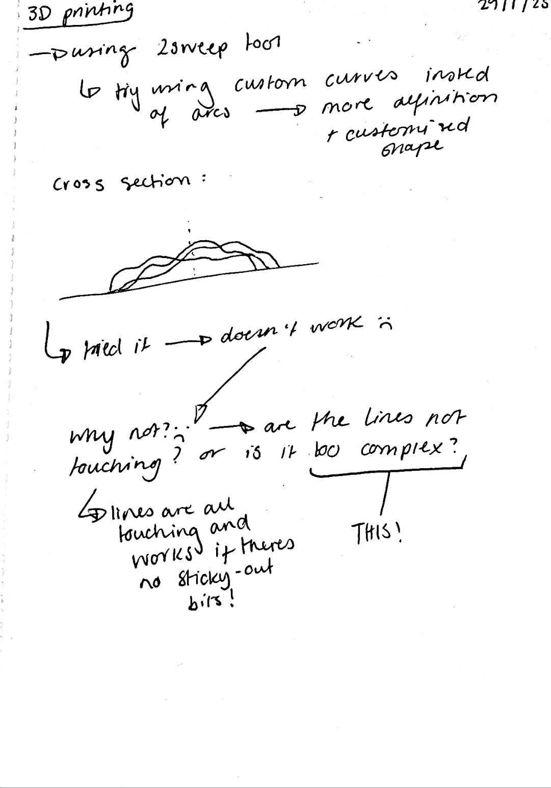
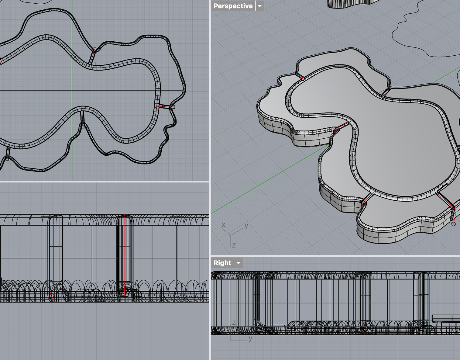
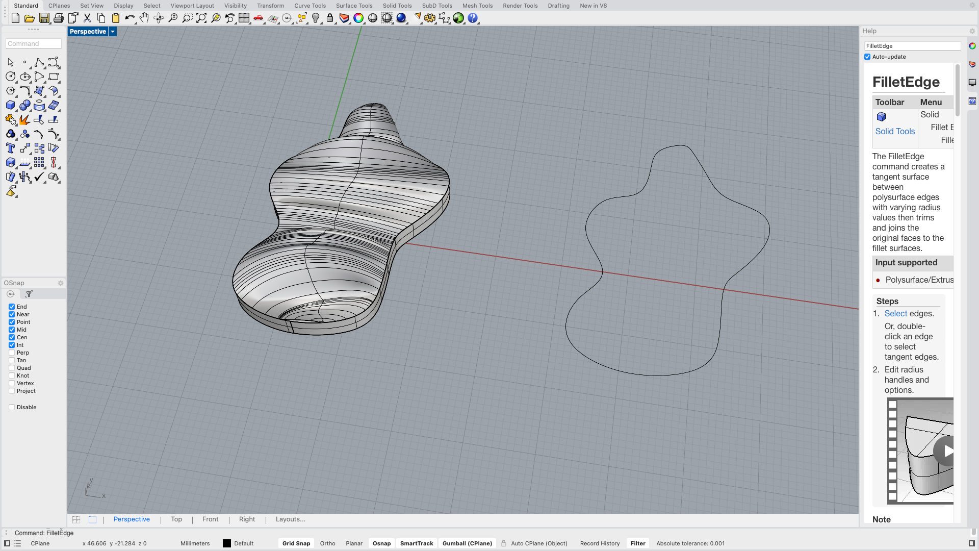
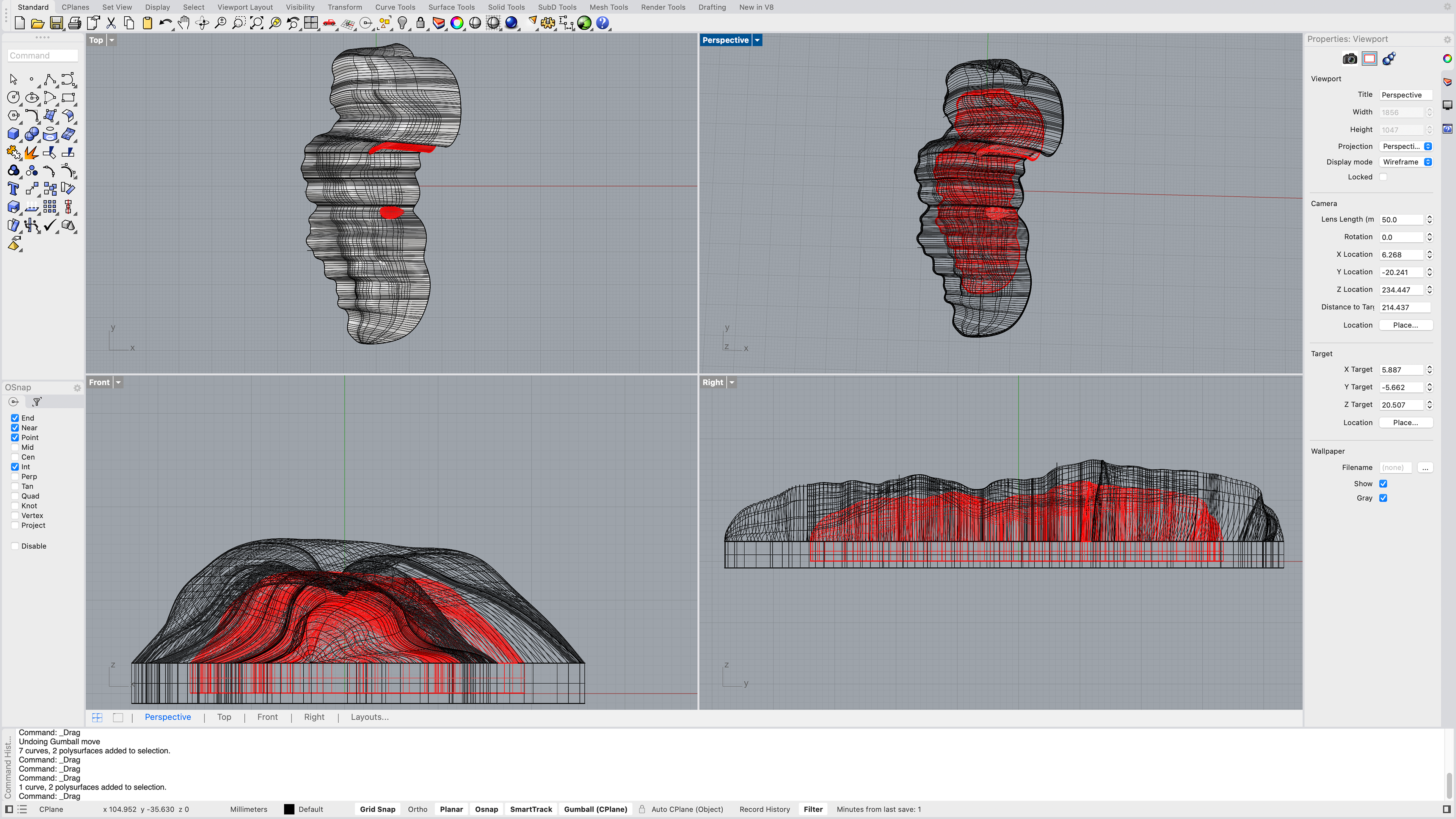
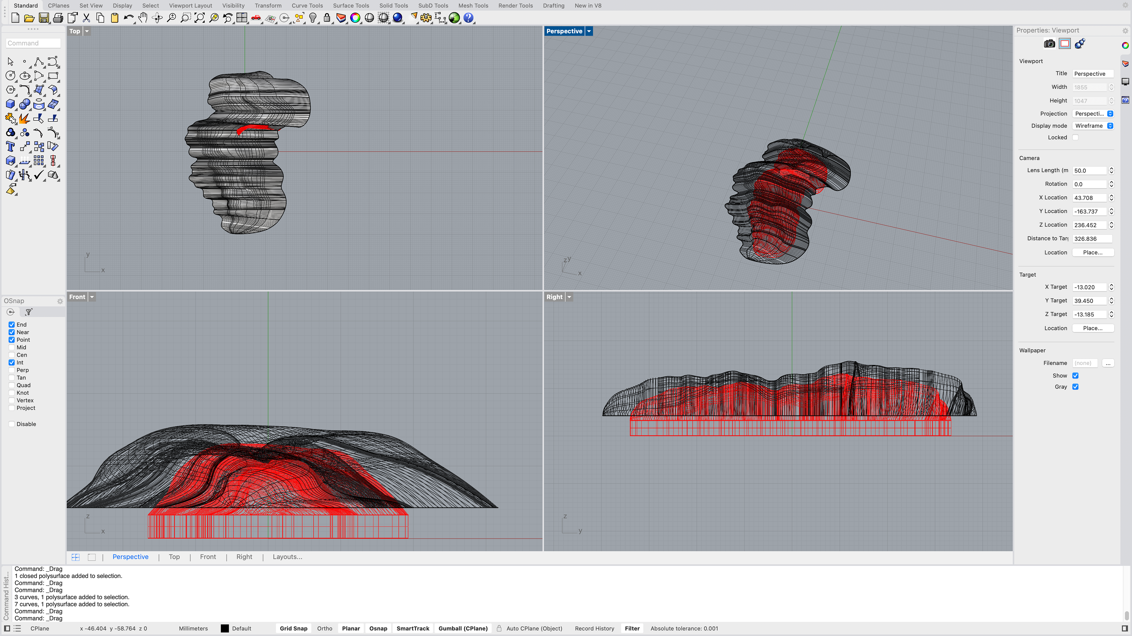
I then attempted to create a new shape (shown below), but I encountered an issue when using the Sweep2 tool—it simply wouldn’t work. Frustrated, I asked Geoff to try to understand why this was happening. He explained that the tool was struggling because my design was too complex, which confirmed my suspicions. I had a feeling that the intricacy of the shape might be pushing the limits of what the tool could handle, but I wasn’t entirely sure how to work around it.
Geoff went on to explain that I was relying too much on the software to make decisions for me, rather than taking full control of the modelling process myself. He emphasised that I needed to guide the program rather than let it "think" for me. This advice completely shifted my approach. Instead of trying to force the tool to work on the entire shape at once, I realised I needed to break the model down into smaller, more manageable sections.
By splitting the shape into multiple parts, I gained greater control over the placement of curves and edges. I also hoped that this adjustment would have another major benefit, and reduce the need for extensive sanding after printing since I could refine each section individually before finalising the design.
With this new method, I was able to use the Sweep2 tool on each separate section, ensuring that the curves and transitions were smooth and precise.
This experience taught me an important lesson about working with digital tools: while they are incredibly powerful, they still require careful input and direction from the user. Simply relying on automated functions without understanding their limitations can lead to frustration and inefficiencies. Moving forward, I became more mindful of breaking down complex shapes into simpler components, allowing for a more controlled and intentional design process.

Before splitting up the shape
30th January 2025
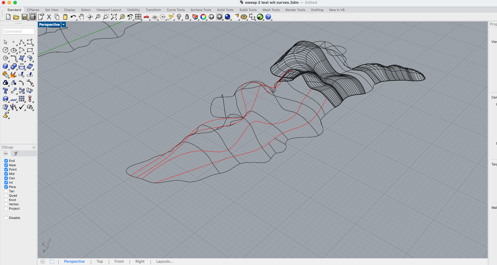
Showing where I split up the shape
After using Sweep2 tool on each section
While using the Sweep2 tool on the different sections, I found that I had to plan which order I sweep the sections. By this I mean, that some sections had the same line but was split into 2 different sections to allow the Sweep2 tool to work correctly. I found it easier to do the smaller sections first, and then join the lines together to make use Sweep2 on the larger sections. The video below shows what I mean by this.
x4 speed
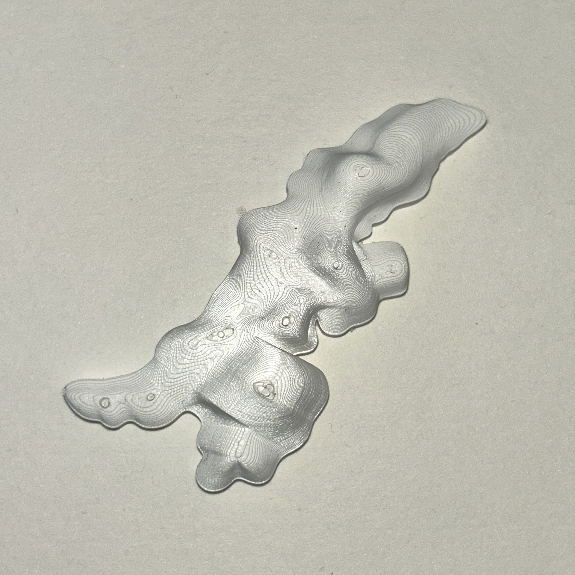
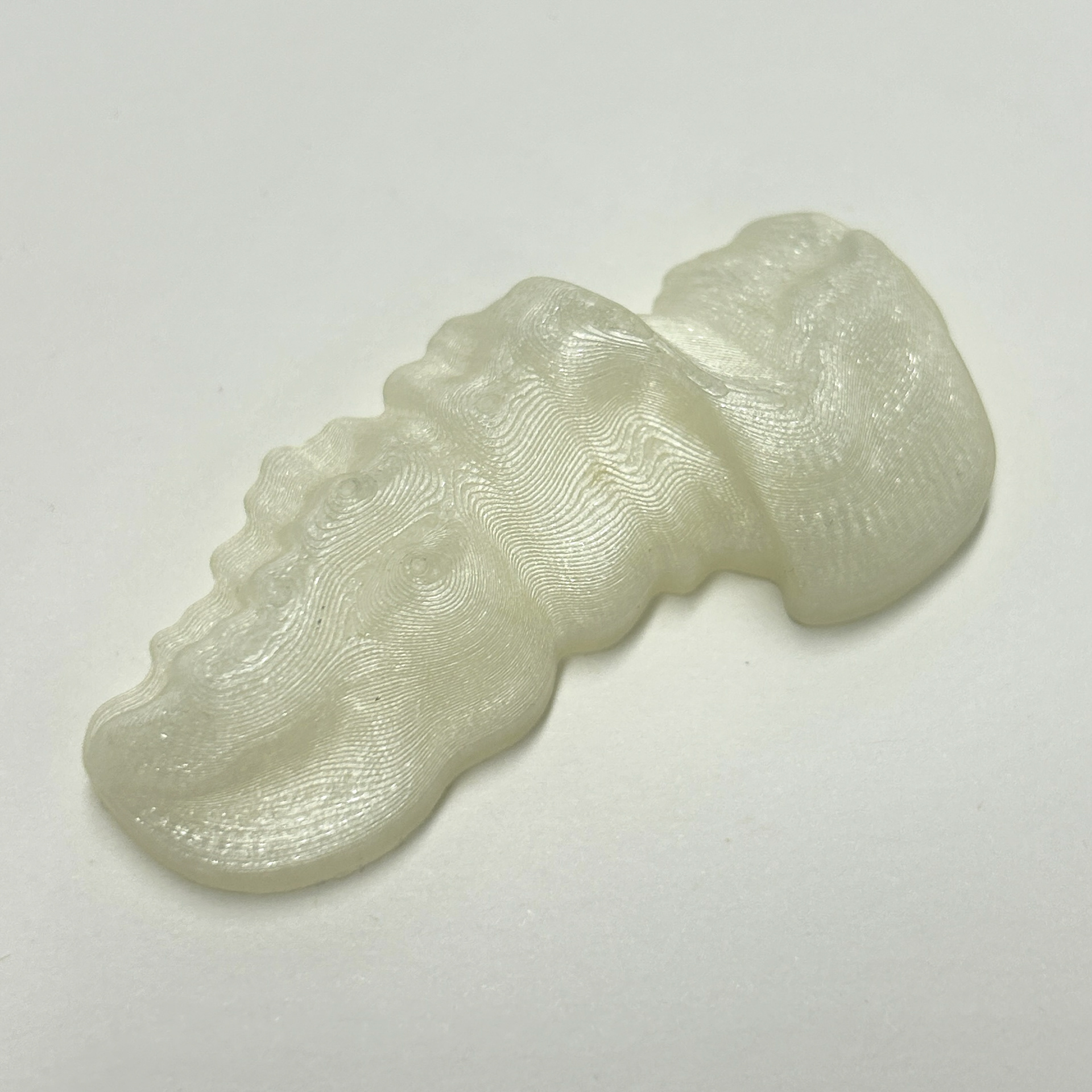
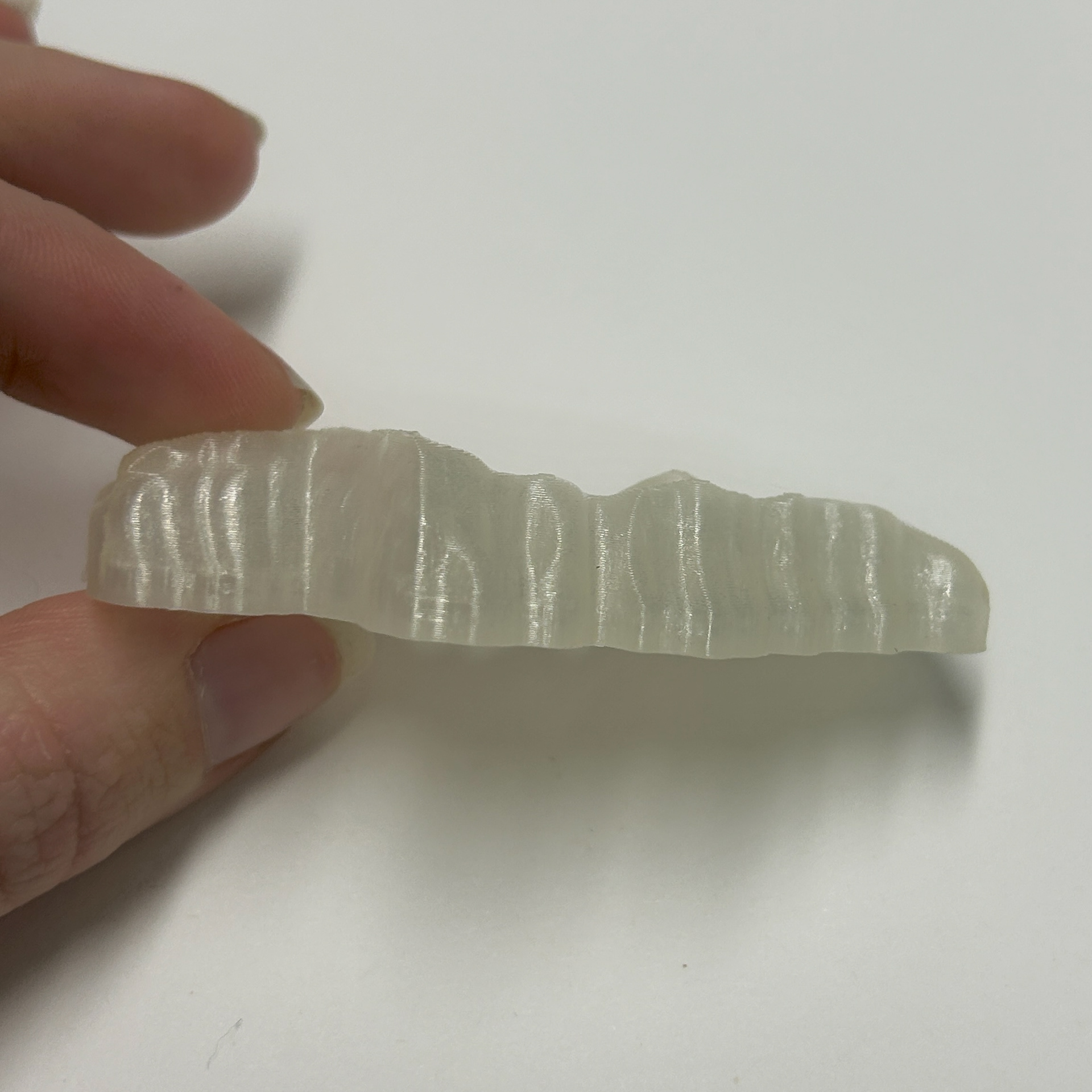
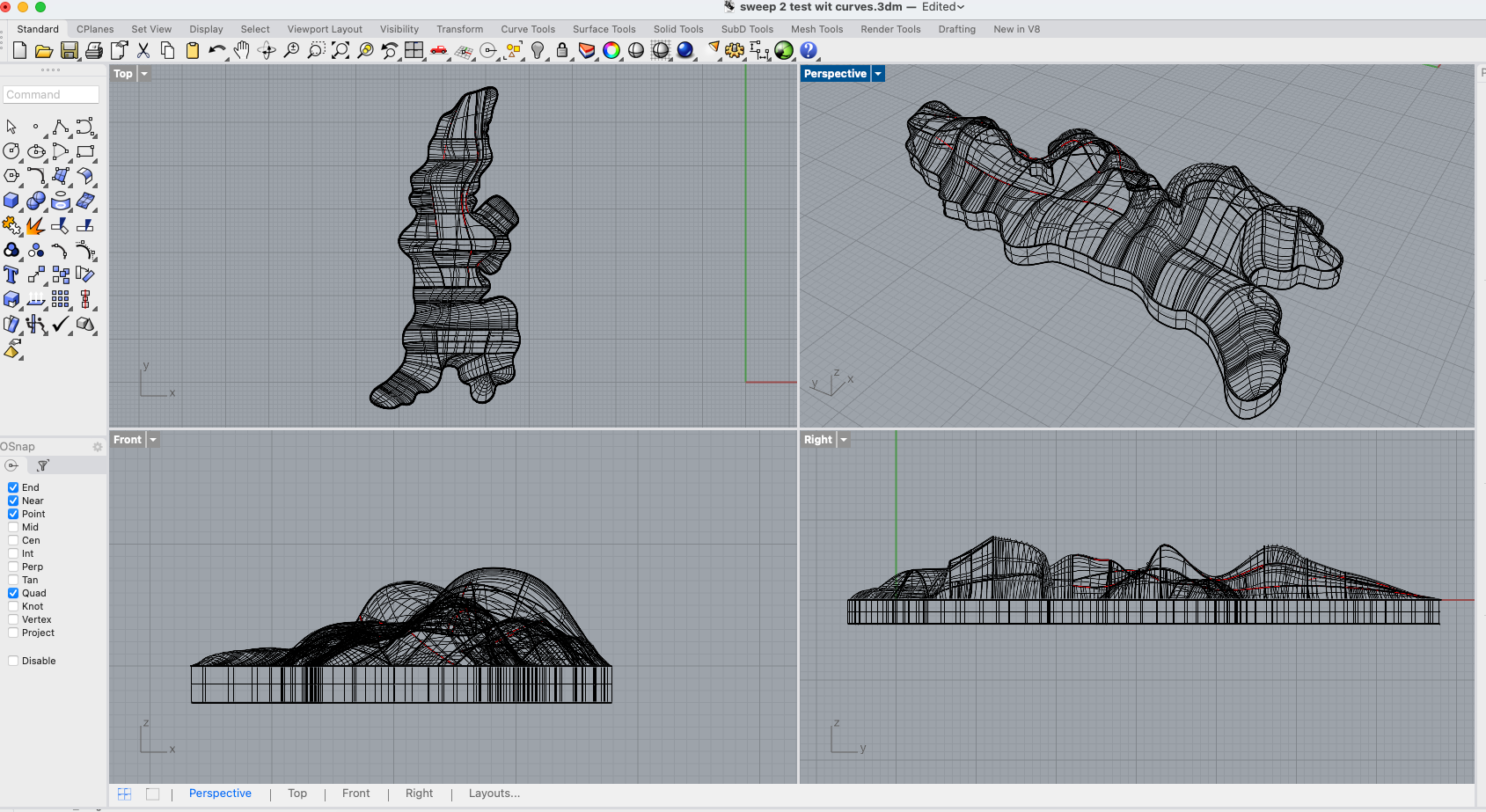
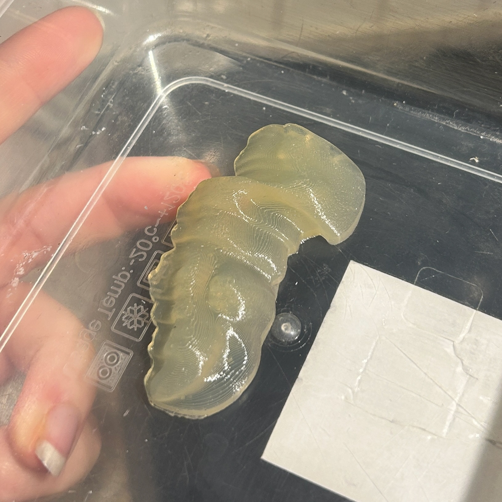
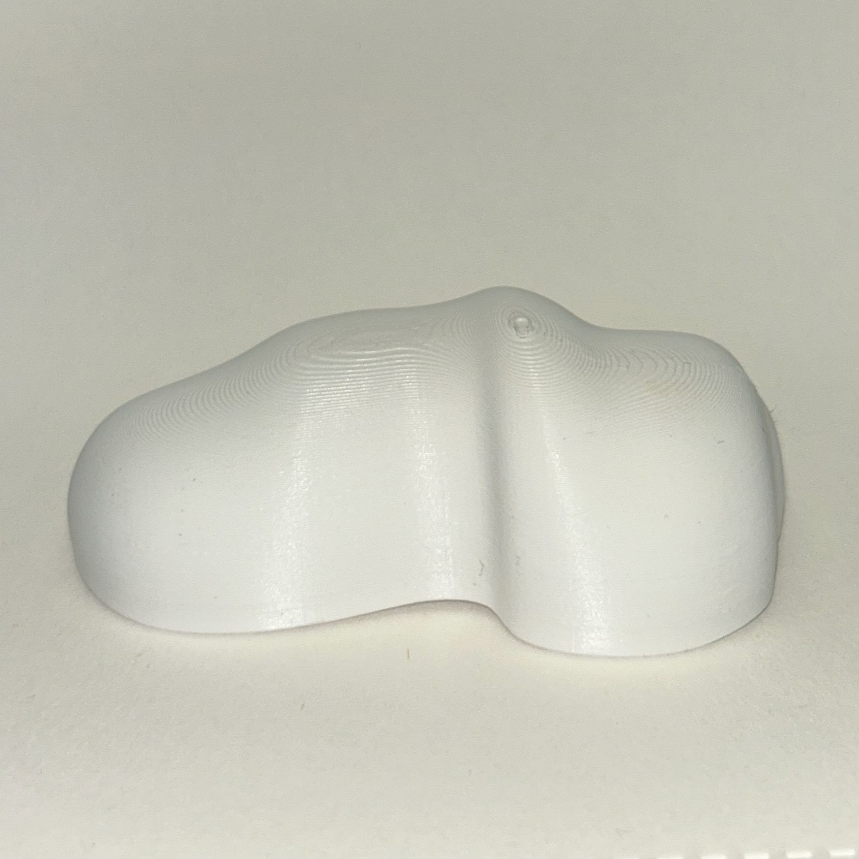
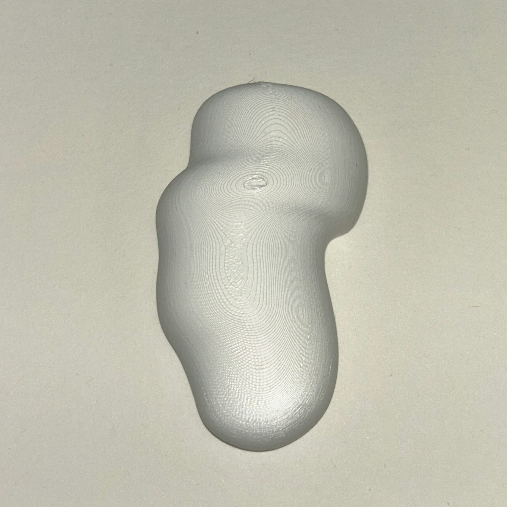
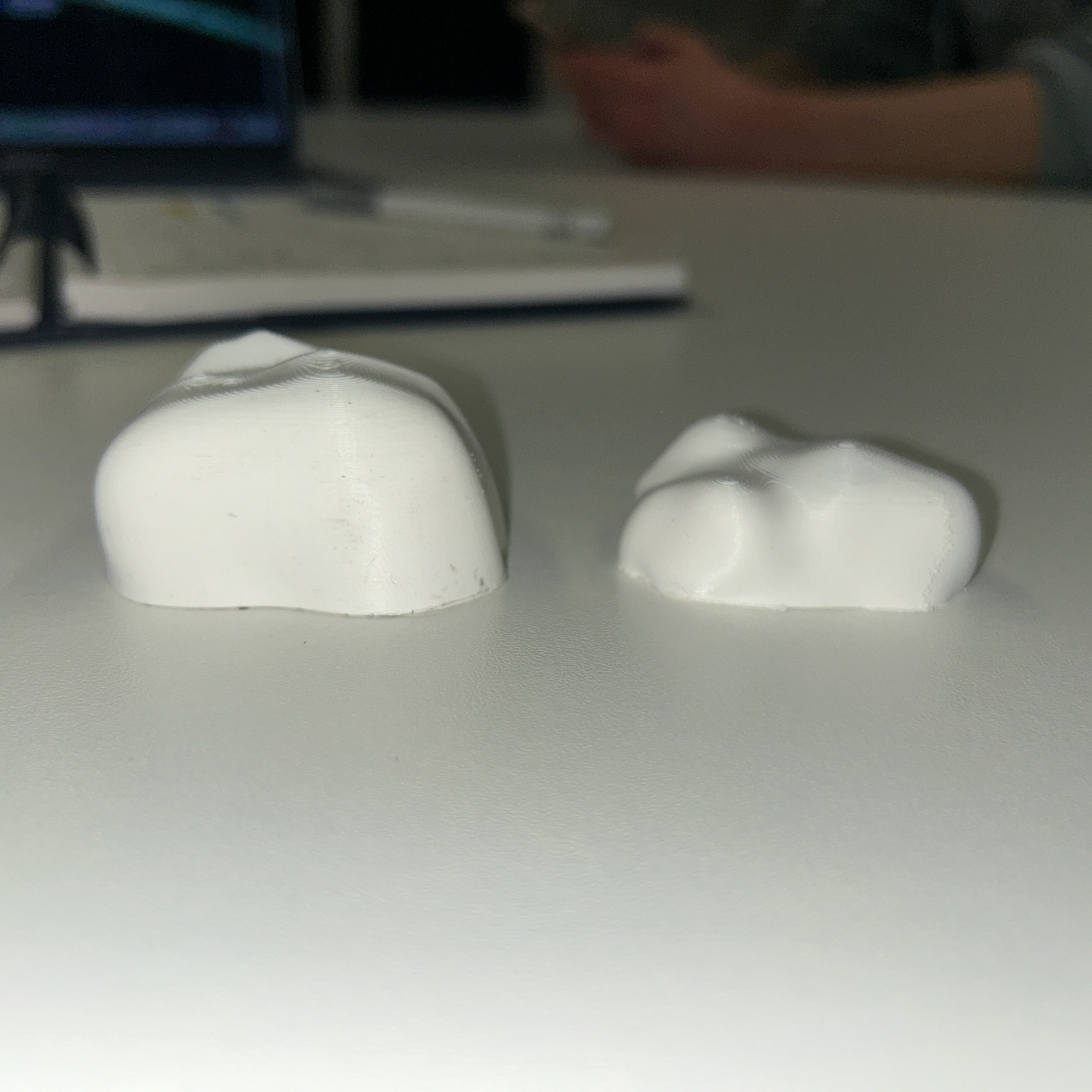
I then printed this test piece to see how it looked in physical form. Seeing the object in real life gave me a much clearer understanding of its strengths and areas that needed improvement compared to a Rhino render. One issue I immediately noticed was some sharp edges, likely a result of using the Sweep2 tool in Rhino. This was something I needed to address, but at the time, I wasn’t entirely sure how to fix it aside from adding more sections to break up the shape.
Despite this, I was pleased with the complexity and overall form of the design. The height was slightly inconsistent throughout the model, but I actually liked this variation - it gave the piece a more organic feel. However, I did want to refine the transitions to make them smoother. Additionally, I noticed a few undercuts on some of the extending pieces branching off from the main shape. While this was not ideal, I was confident that they could be adjusted and improved with further refinements in the modelling process.
Overall, this test print was incredibly useful in highlighting both the strengths and the areas for improvement in my design. Moving forward, I plan to experiment with different techniques in Rhino to refine the shape further while maintaining the complexity I liked.
More CAD Testing
4th February 2025
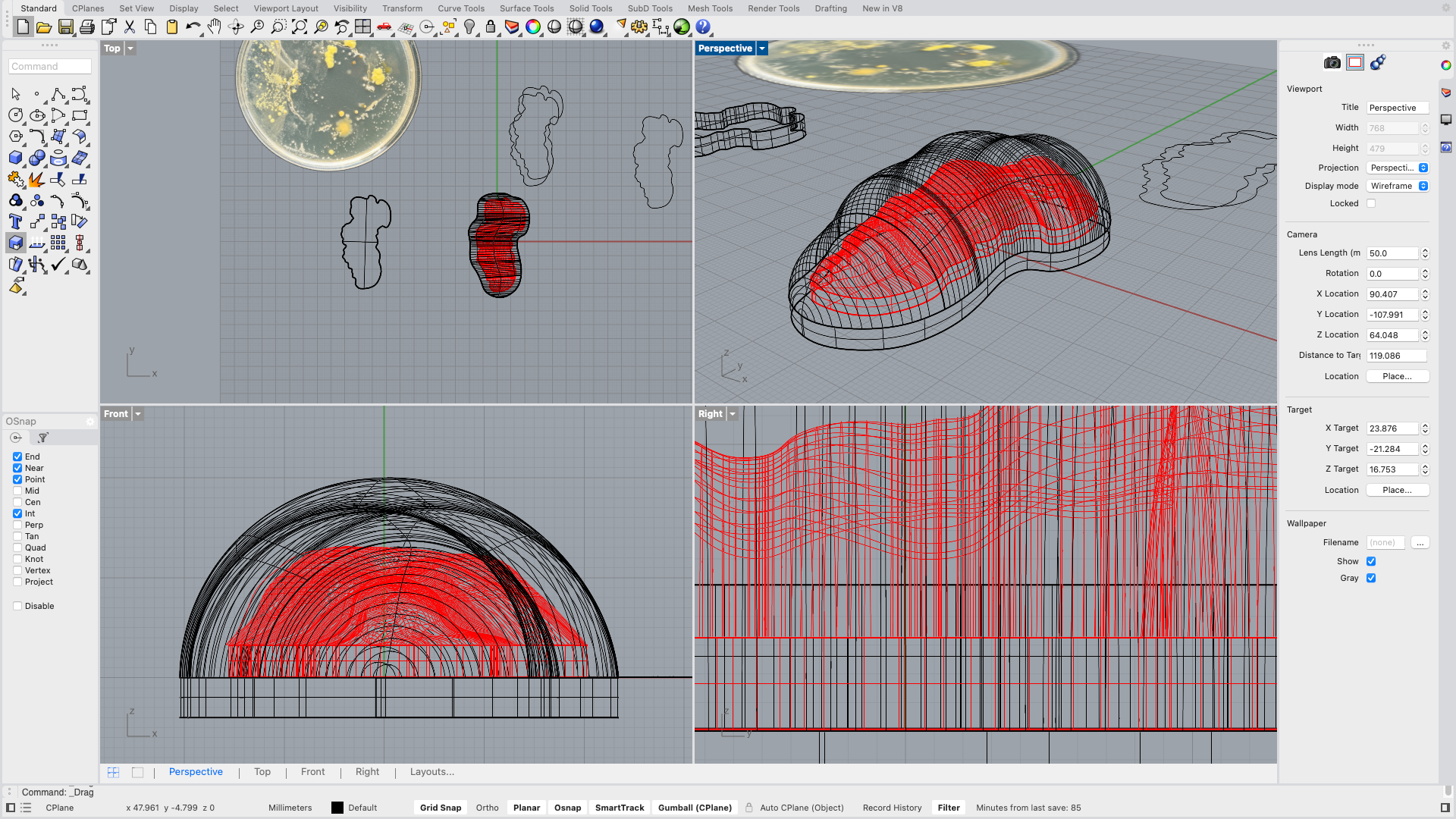
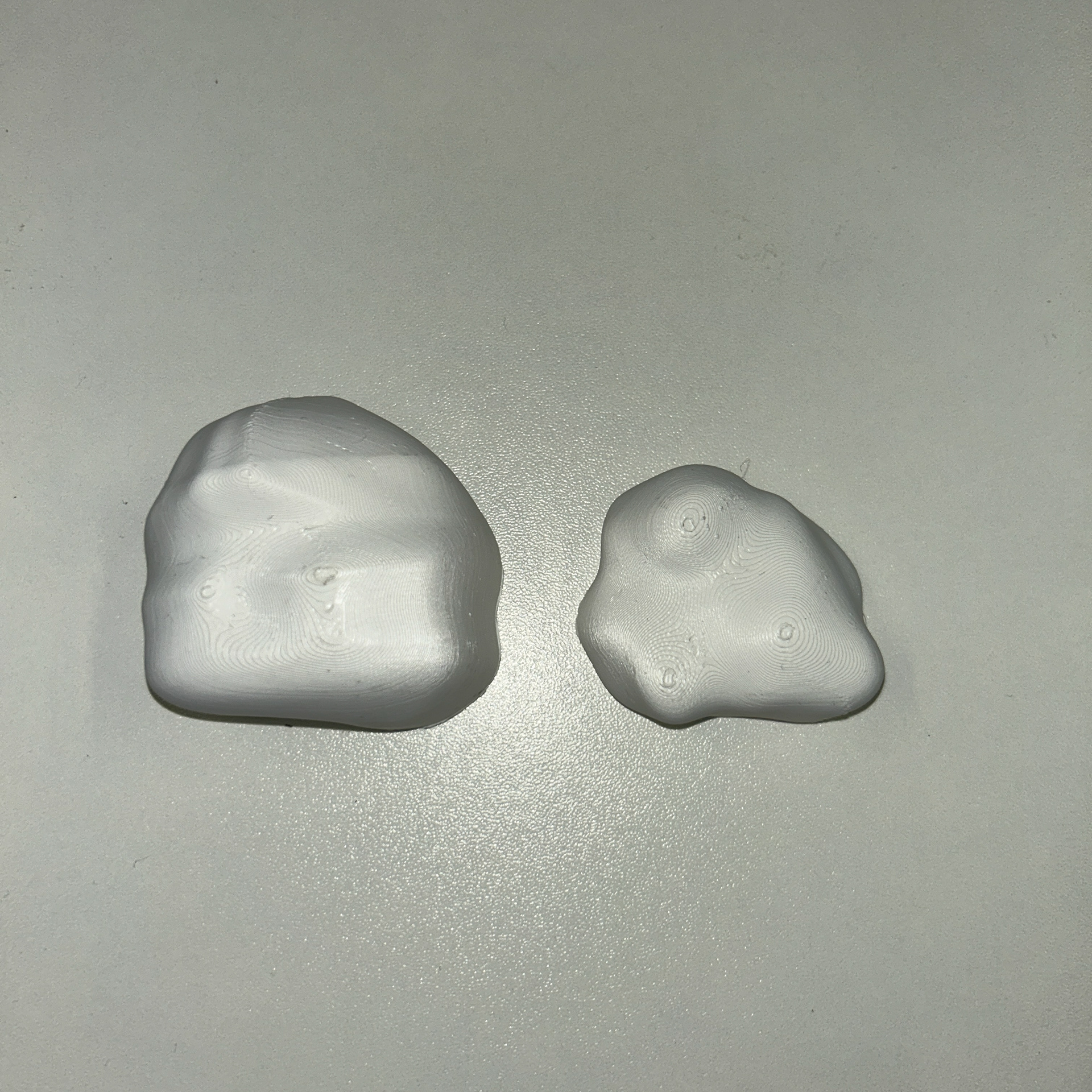
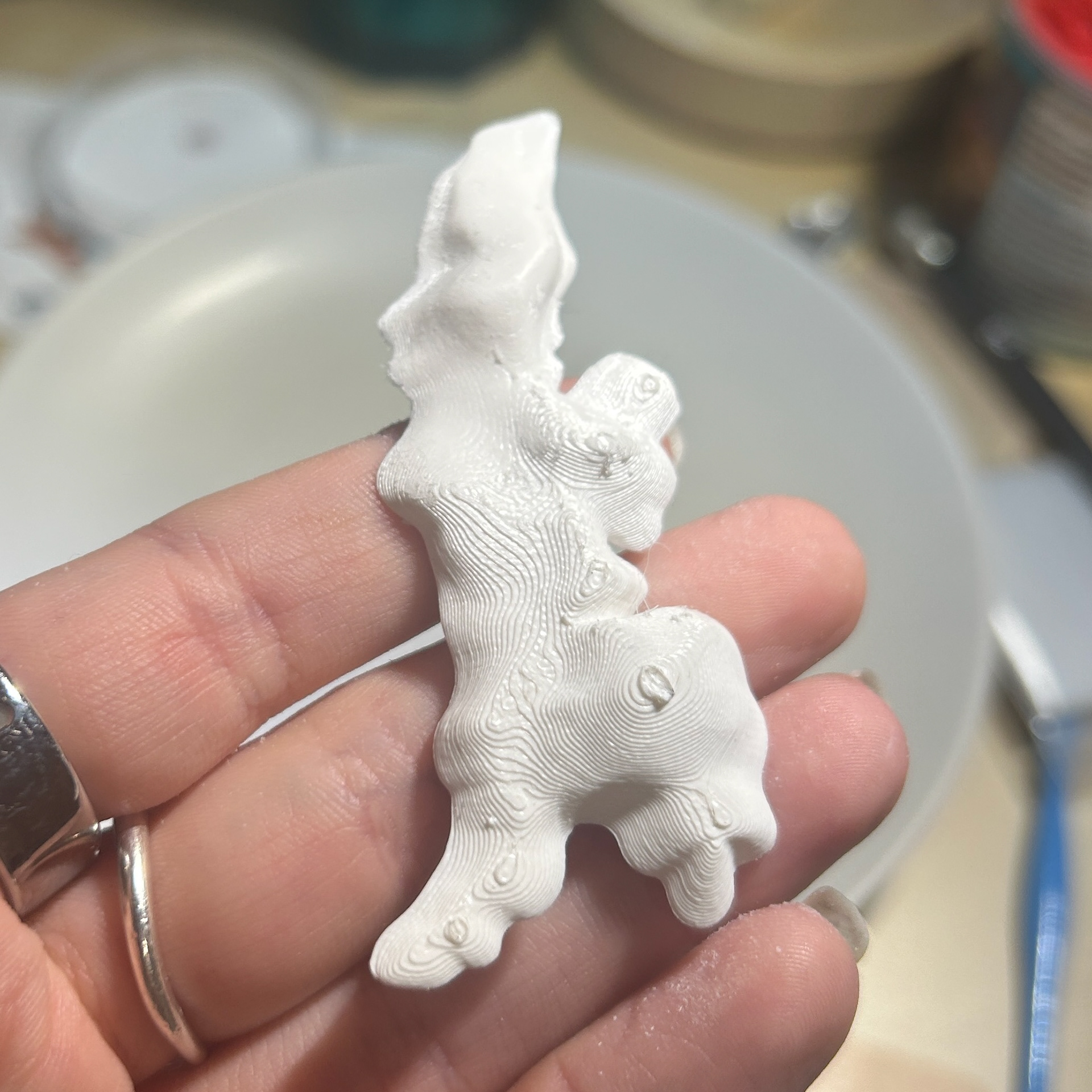
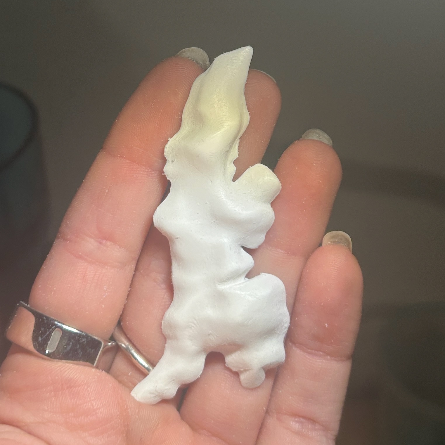
After reflecting on my previous attempt using Sweep2 and splitting up the shape, I then made another sample. I used the same idea of using the custom curves to create the height, however, I tried to simplify the shape slightly as this would help with cleaning up of the contour lines and resin later on. I also made this sample larger, to see which scale I preferred.
Original print
After beginning to sand the top
I then attempted to sand the piece using both my Dremel tool and sandpaper, While I quite like the look of the contour lines, I know from Unit X that these do not work well with resin, and make it very difficult to see the bacteria on the inside.
Making 3D Prints using Blender
While I was happy that I was beginning to make progress on my shapes in Rhino, they were still not as smooth as I had liked them to be. Where I had added the lines to break up the sections, these had become visible in the final print. I had tried sanding this which did get rid of the lines, but added more time.
Despite being adamant that I was not going to use Blender, I knew that sculpting the object in Blender was definitely going to achieve the smooth lines that I wanted.
I had never used Blender to make something for 3D printing, so I knew that I would have to create a flat base for the printing bed. Before sculpting a simple shape, I first worked out how to achieve a completely flat base.
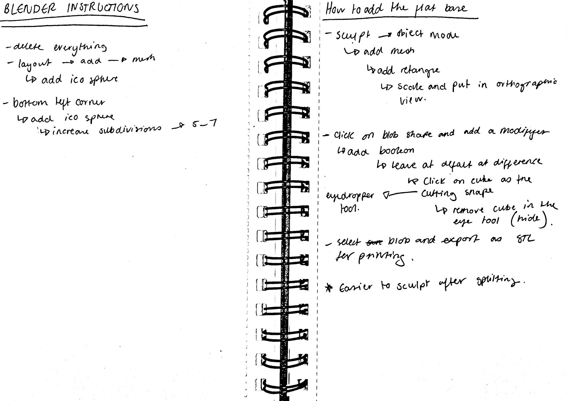
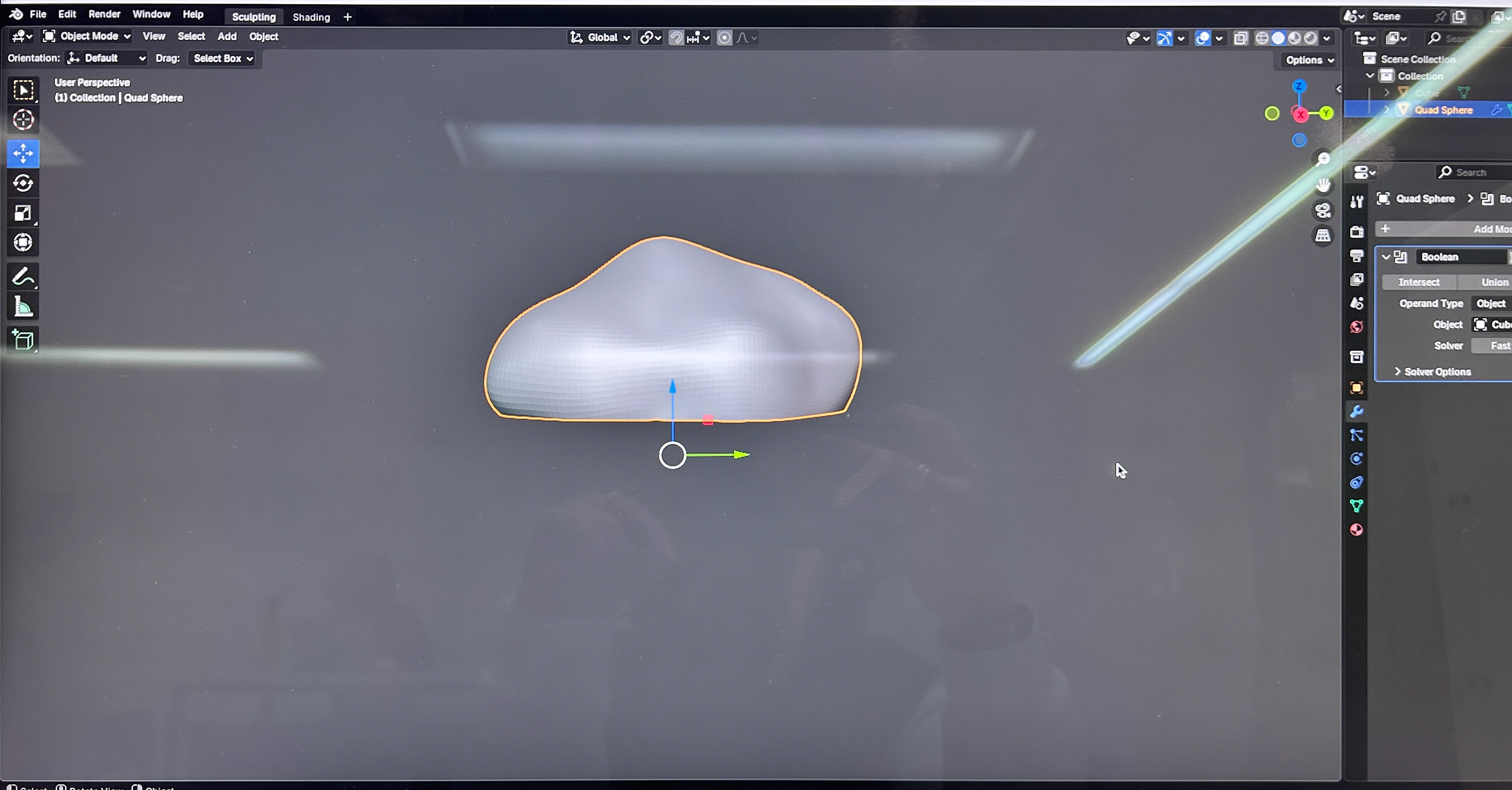
How I make a flat base in blender using the boolean modifier
Showing how I create a flat base using the boolean modifier
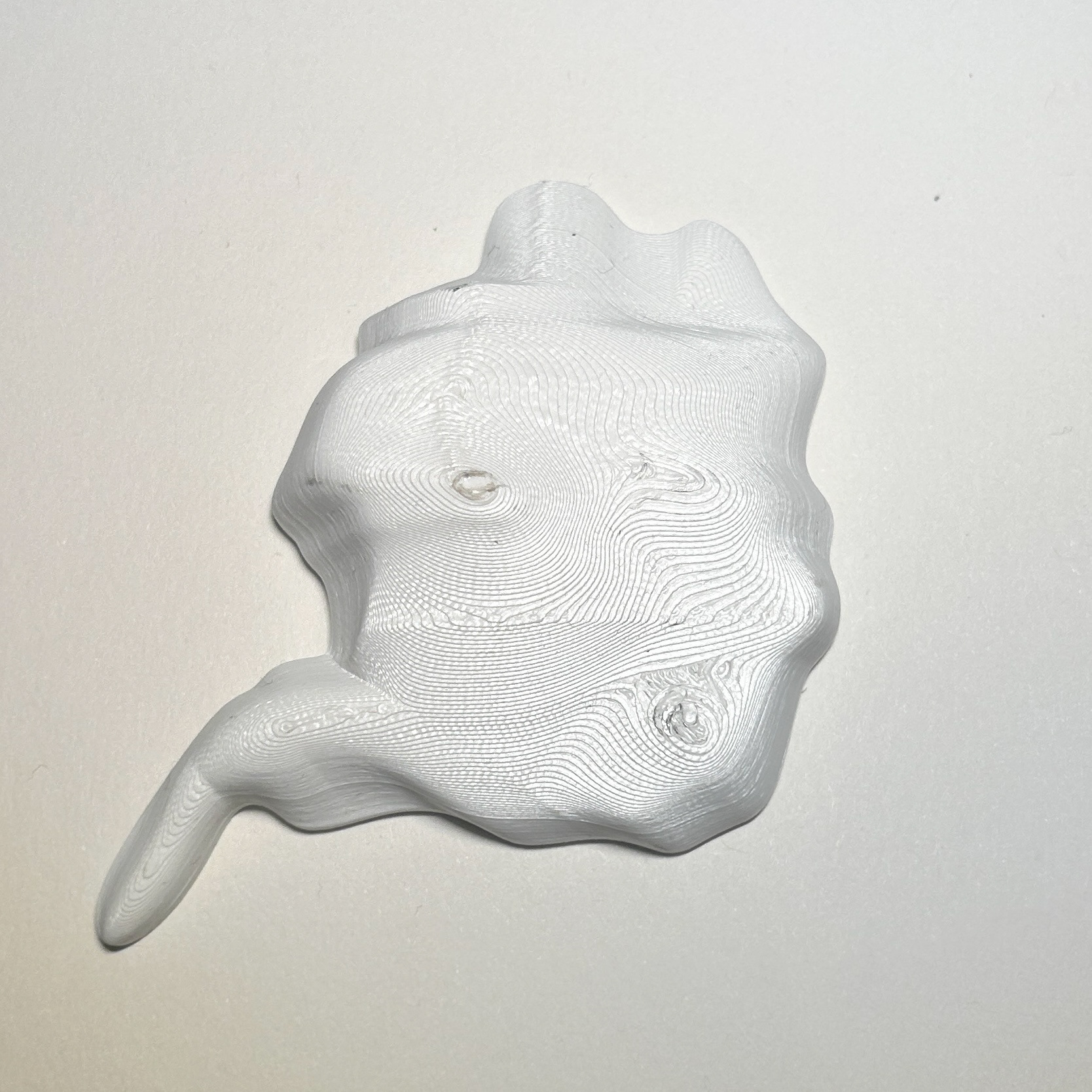
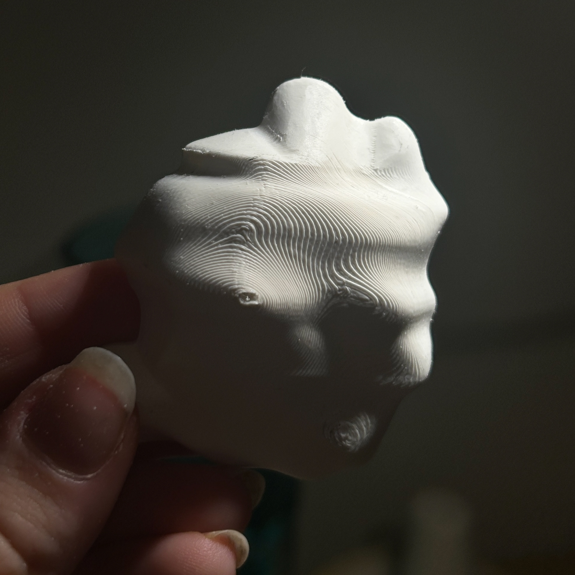
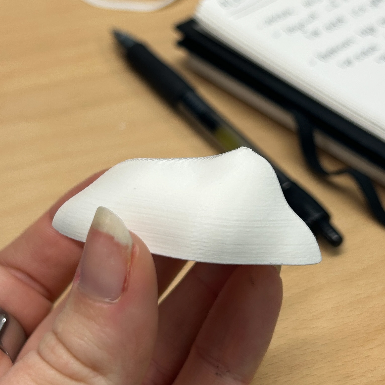
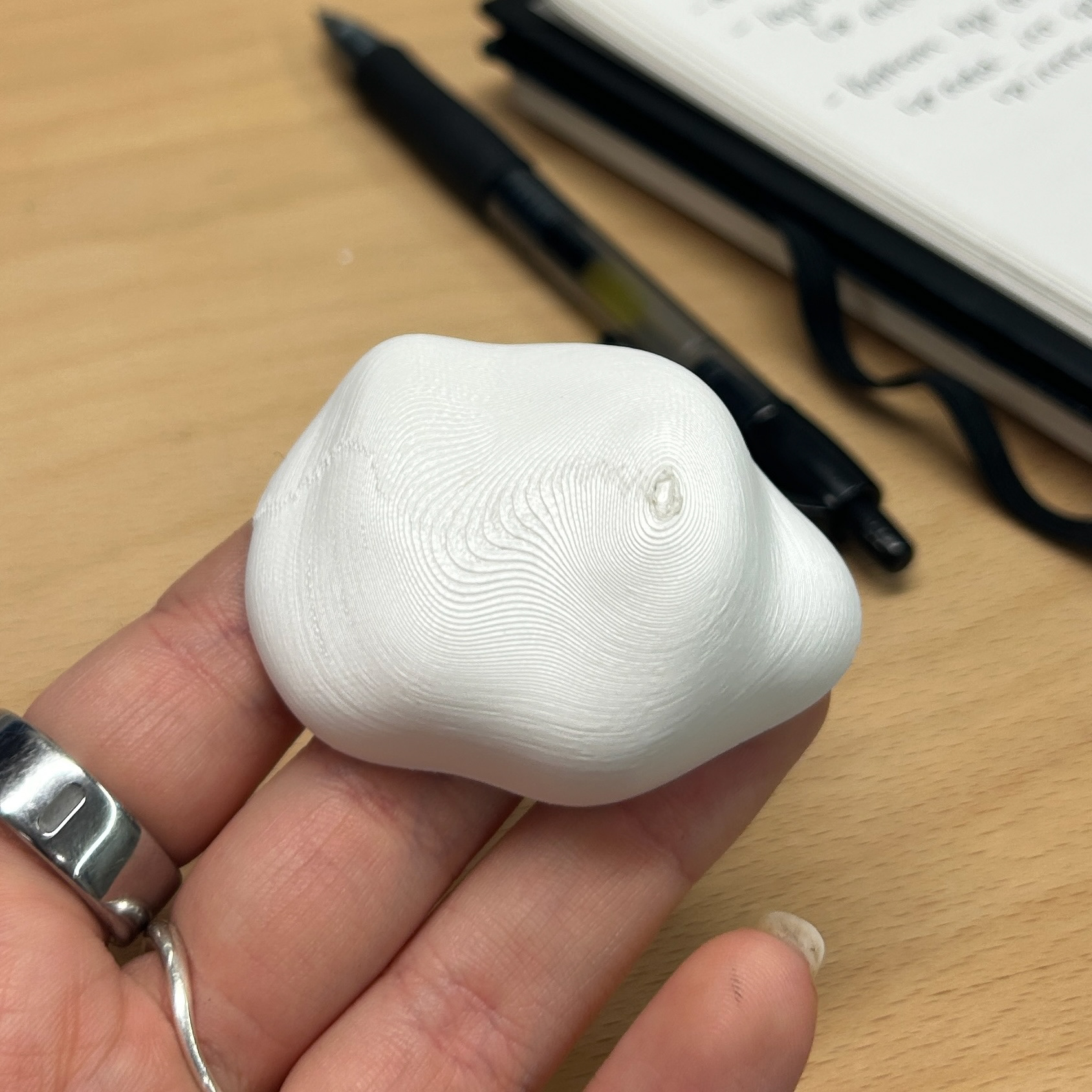
I then started to sculpt my shape in Blender starting with an iscosphere as the base. I used the sculpting tools to drag and manipulate the shape to match that of a bacteria growth from a plate from Unit X.
Growing Bacteria on a 3D Surface
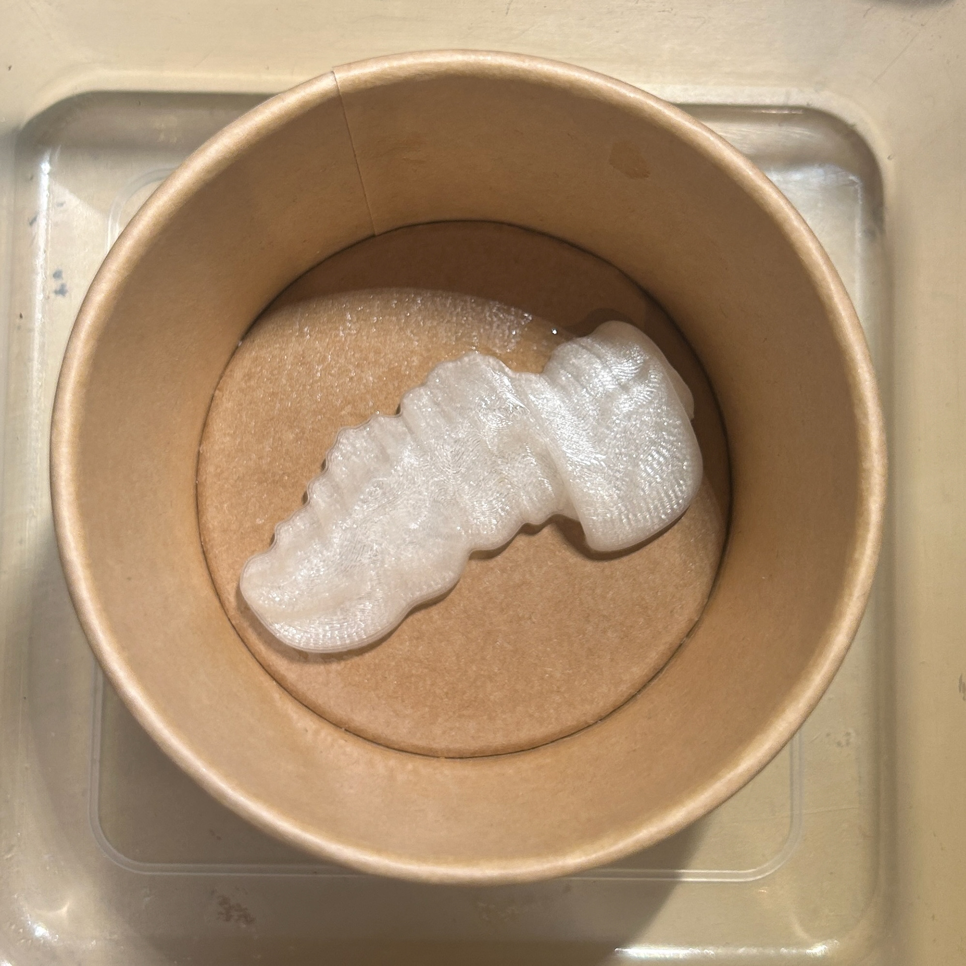
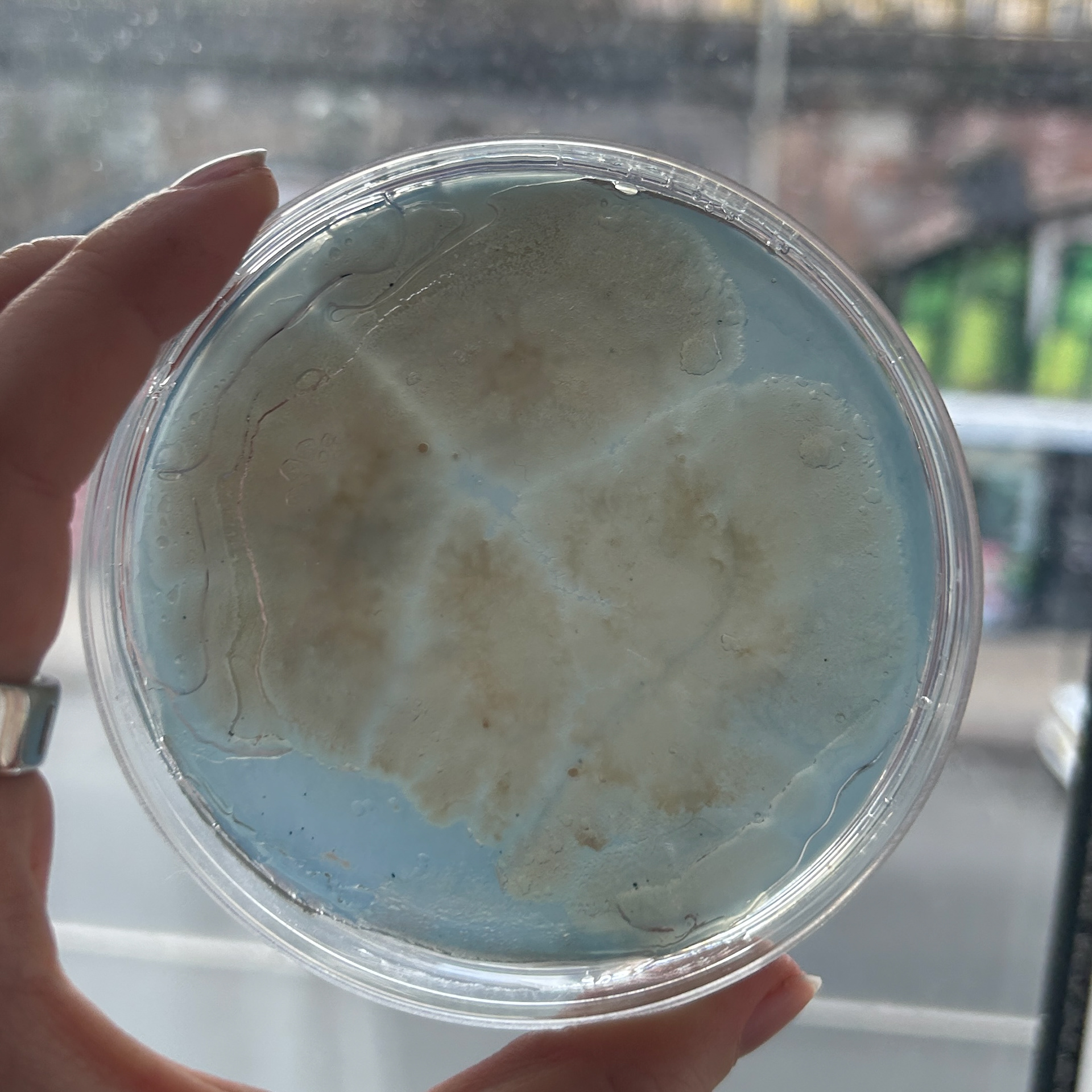
At the start of this project, I knew I wanted to explore the idea of growing bacteria on a 3D surface. To test this, I used one of my 3D prints to create a silicone mould, which I then used to cast my nutrient agar.
Since I had never attempted to grow bacteria on a surface like this before, I wasn’t entirely sure how well it would work. Although I was using the same nutrient agar formula as in my previous experiments, I wasn't sure whether the changes in surface area would impact bacterial growth. The texture and shape of the 3D surface introduced variables that I hadn’t encountered with traditional Petri dishes.
Additionally, the agar in this mould was significantly thicker than what I had used in standard Petri plates. This raised another concern, whether the bacteria would still be visible, as the increased thickness made the agar less translucent than usual.
I made this sample while I was still in the process of deciding which CAD software to use. This stage was as much about refining my workflow as it was about understanding how bacteria interact with complex 3D surfaces.
Rhino for Resin Moulds
10th February 2025
Uniform Scale
Non Uniform Scale
Drawing around the object
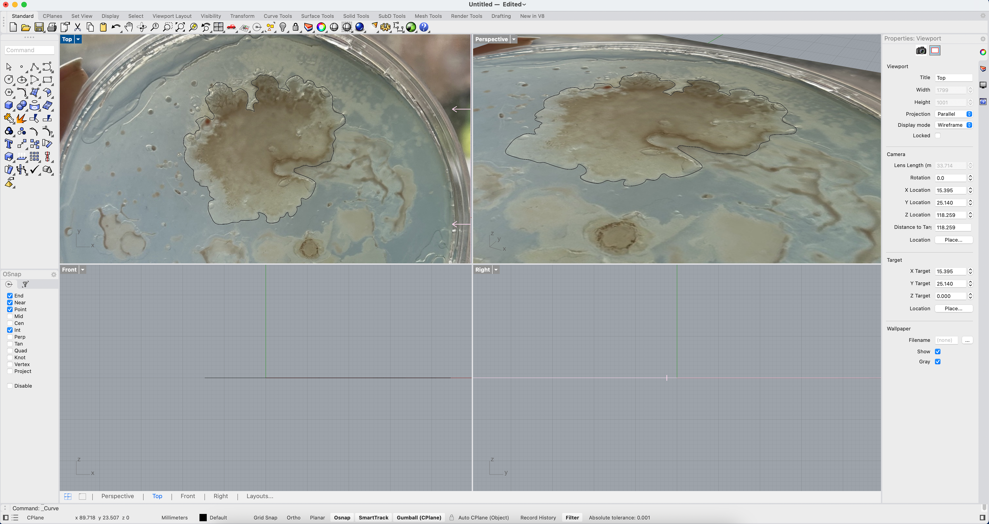
While I was waiting for the bacteria to grow on the 3D agar surface, I needed to go and make a silicone mould for the resin. Initially, I thought I would simply be able to go into Rhino and scale up my shape and print this for the silicone mould, however, this was not the case. Because of the type of shape, it meant that I could not simply uniformly scale the shape as parts were still sticking out. I thought about cutting the agar to fit the shape I would have for the mould, but this was not what I wanted to do. It would ruin the shape as well as the bacteria growth and show the inside of the agar where the bacteria had not grown.
Geoff showed me how to use the non-uniform scale option, however, this still did not work, and the width of the resin around the agar would not be consistent.
From this, I decided to do something different and instead create a new shape in Rhino that would sit around the agar. The agar (shown in red) would then sit directly in the middle of my new shape for the resin.
Encasing the 3D Agar in Resin
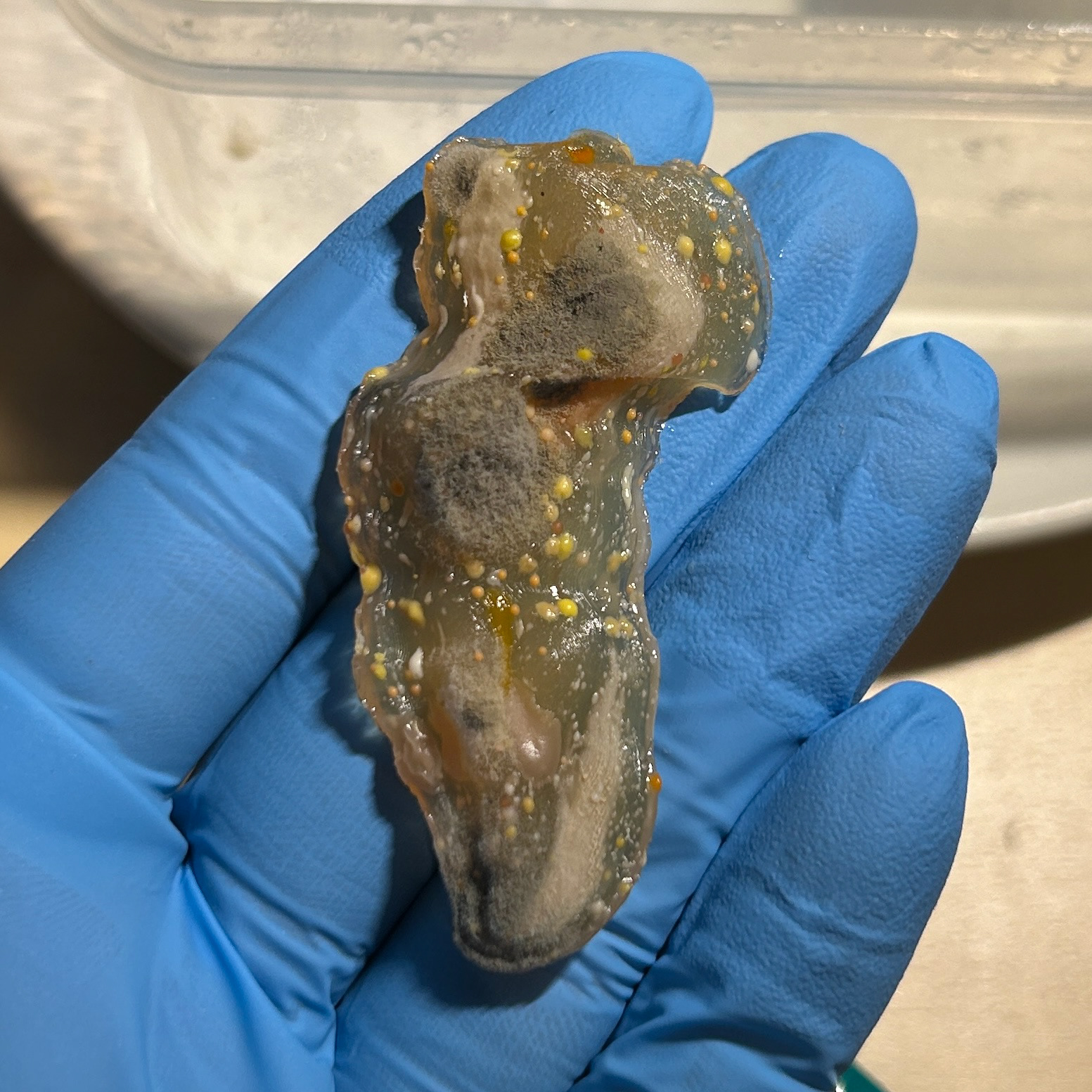
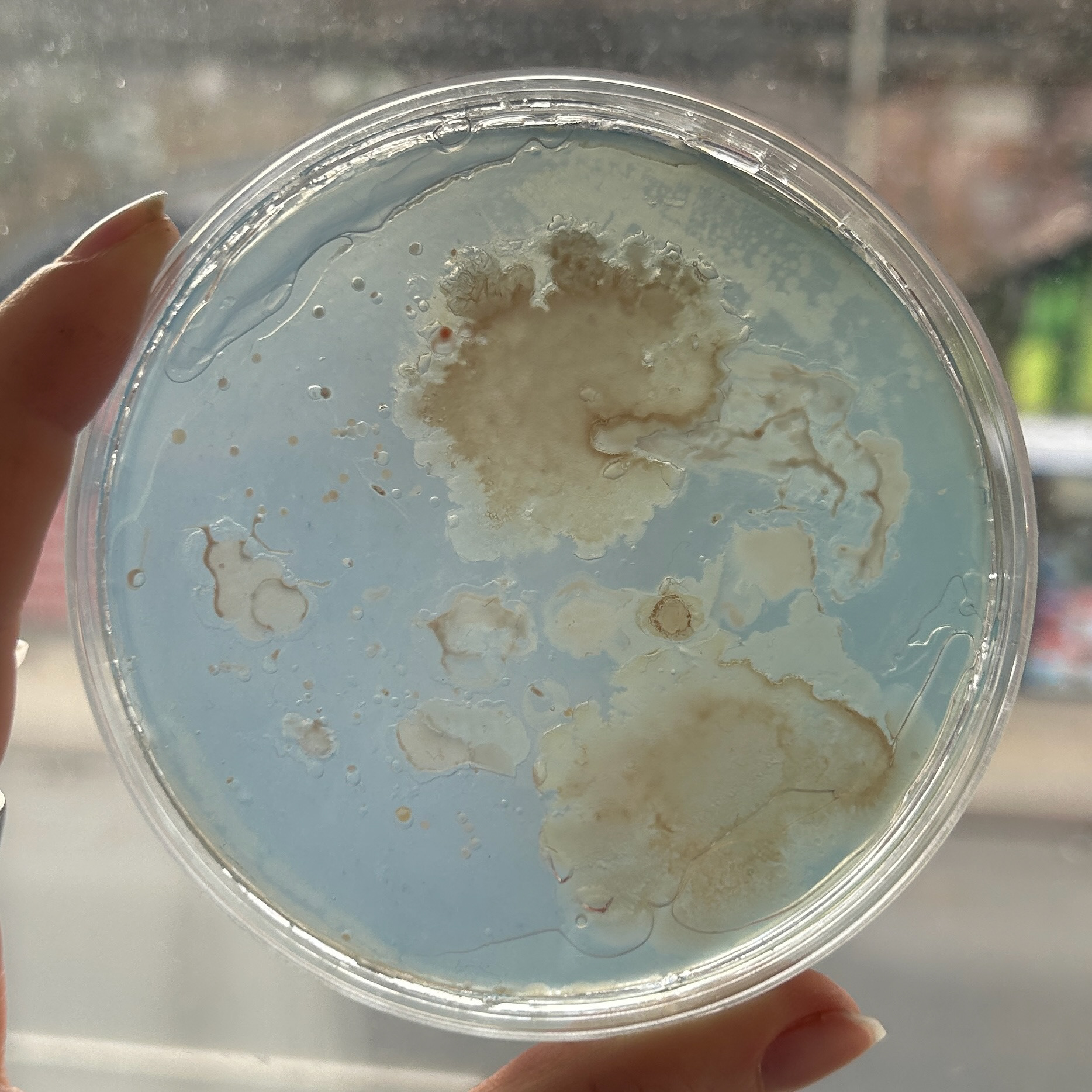
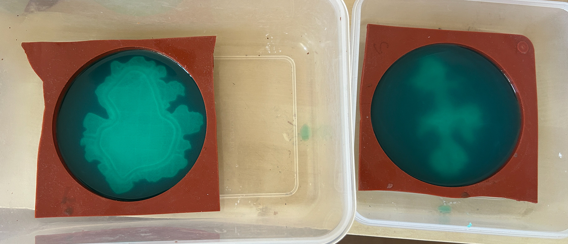
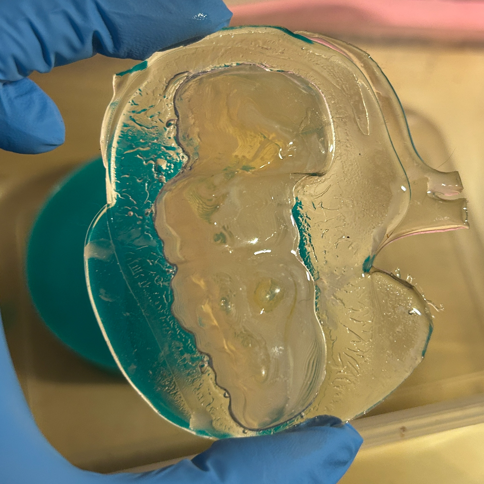
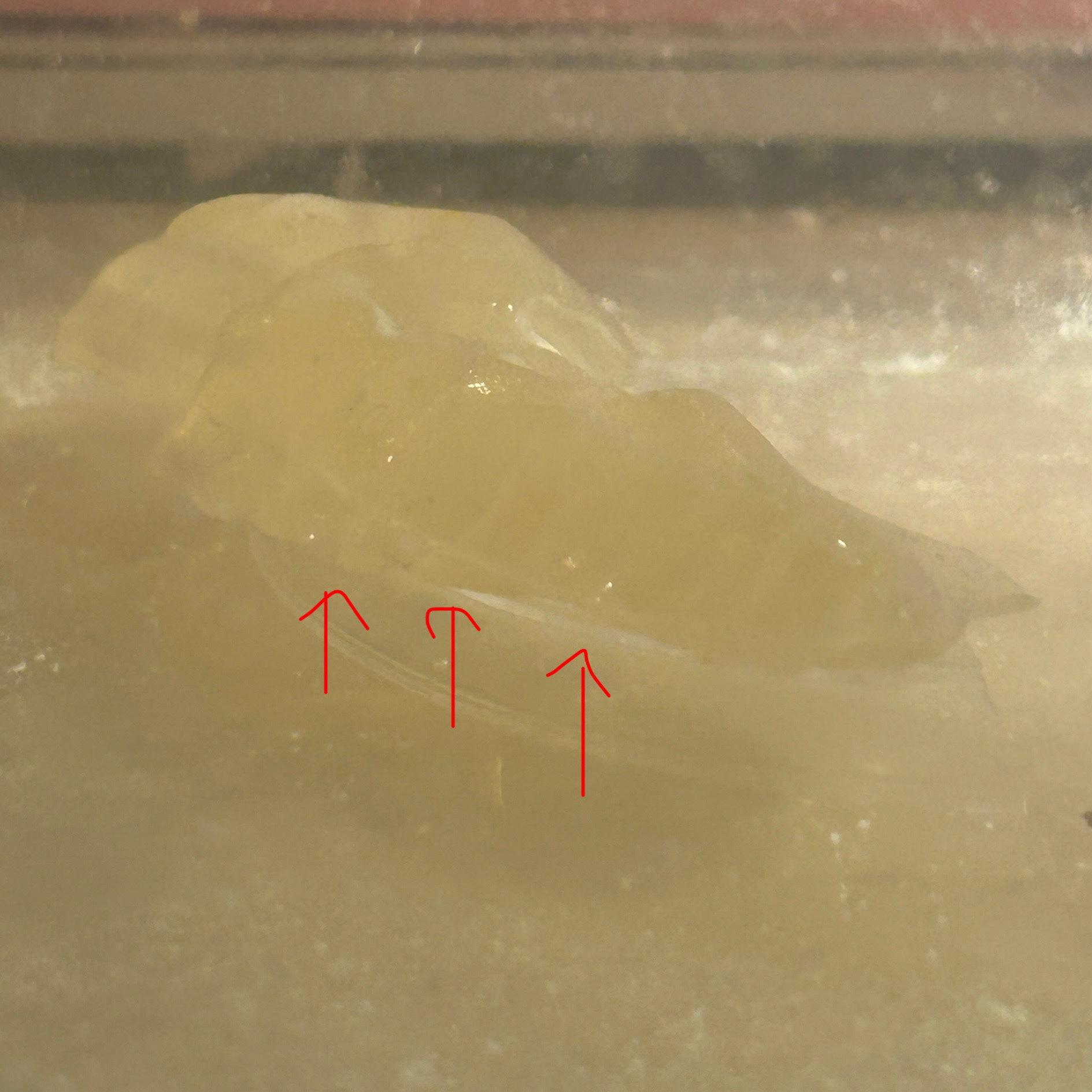
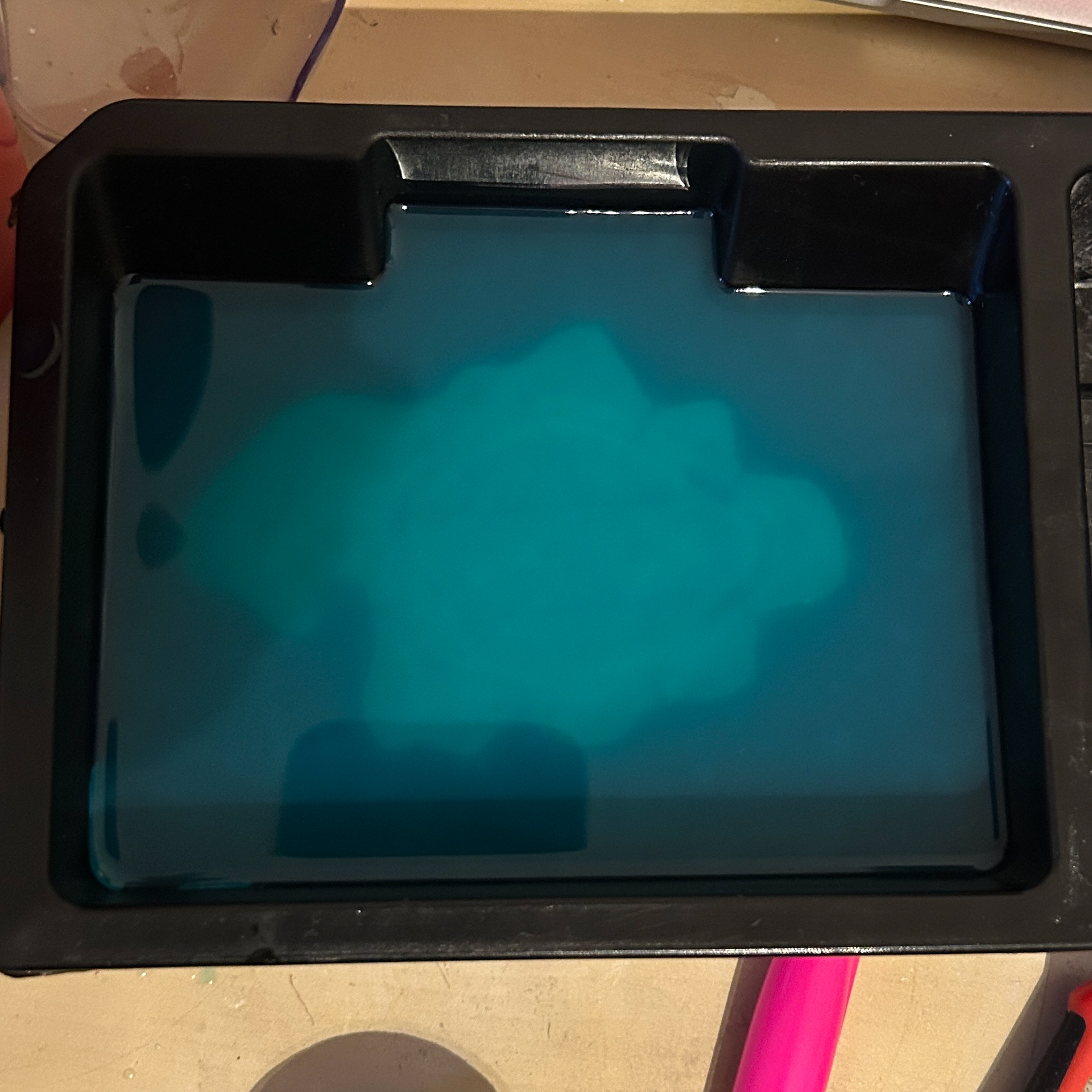
After keeping my nutrient agar sample swabbed with bacteria from my ring in a warm dry environment for 9 days, these were the results.
Usually, I would only keep my samples growing for 6-8 days before sealing with resin, however, I believe that with my flat being very cold at the moment, it may have disrupted how quickly the bacteria grew on the agar.
I was pleased that the bacteria had grown on this 3D surface, however the agar did turn a slightly darker colour. I'm not too sure why this was as the recipe for agar was the same as what I have previously used. However, it clearly did not affect the bacterial growth, so I decided to stop worrying about it.
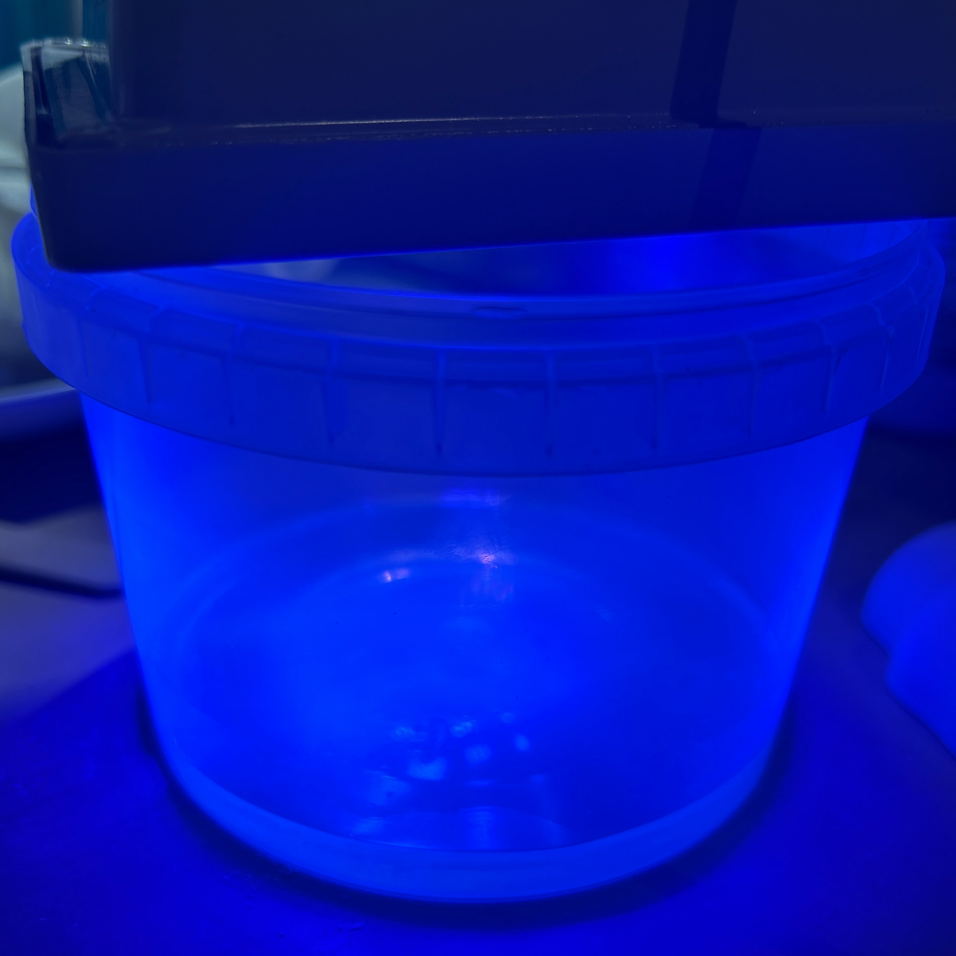
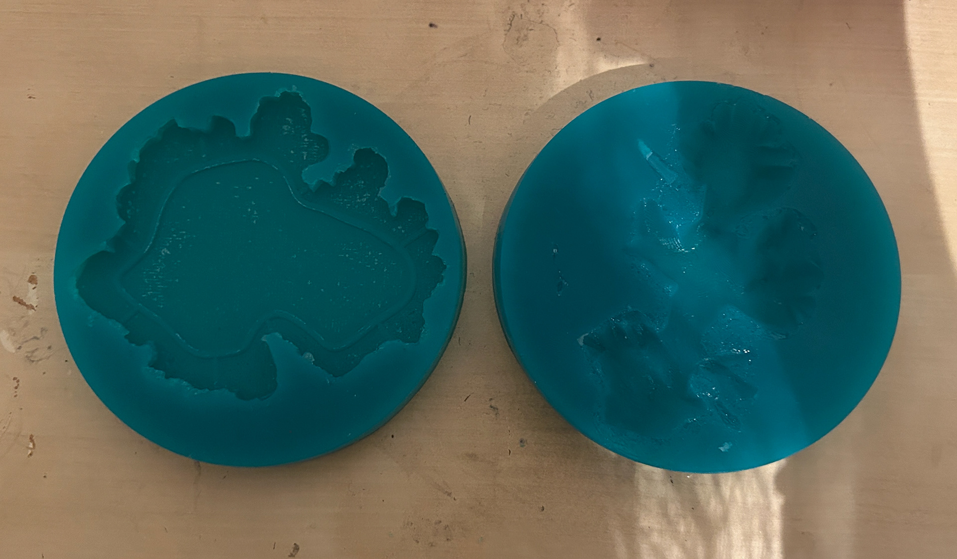
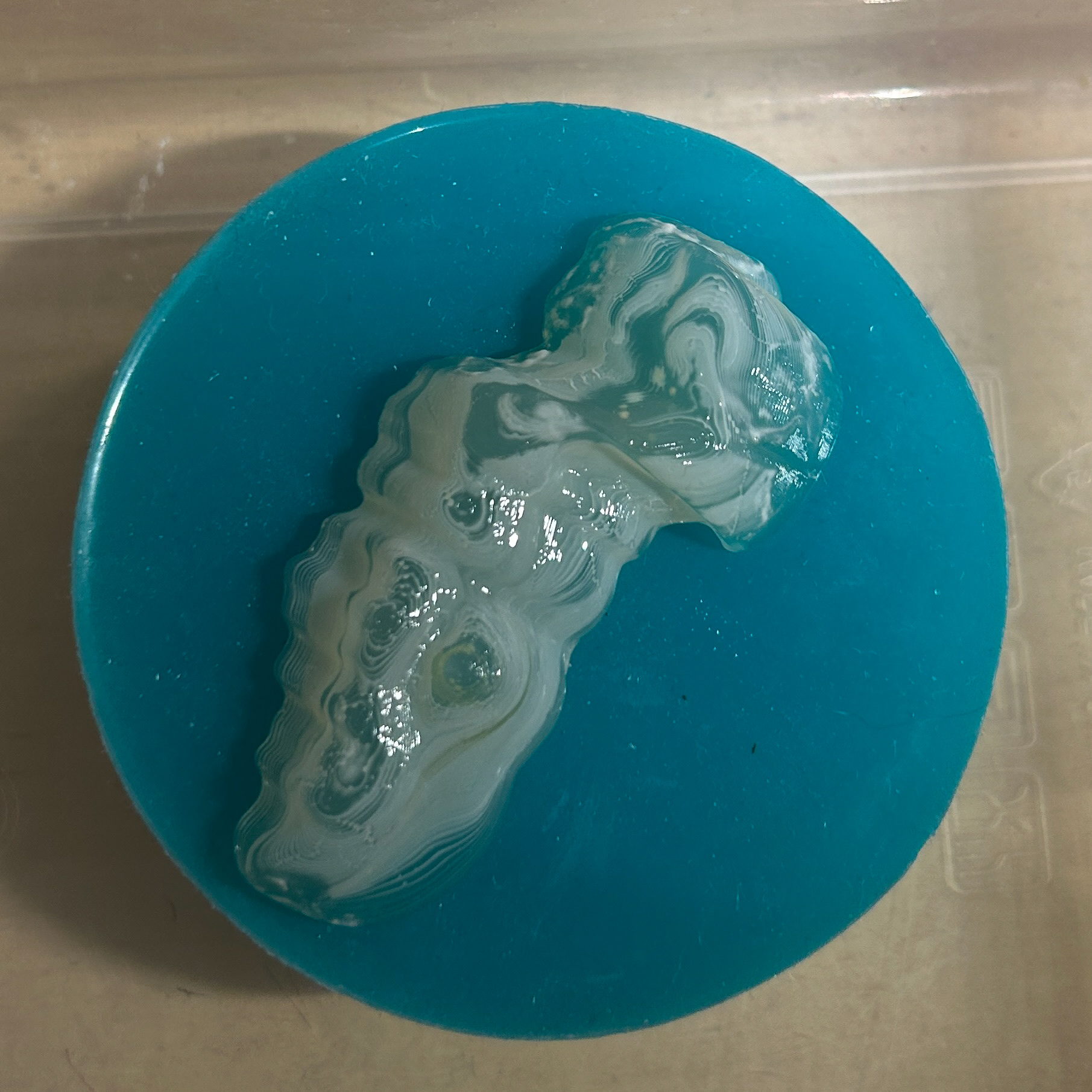
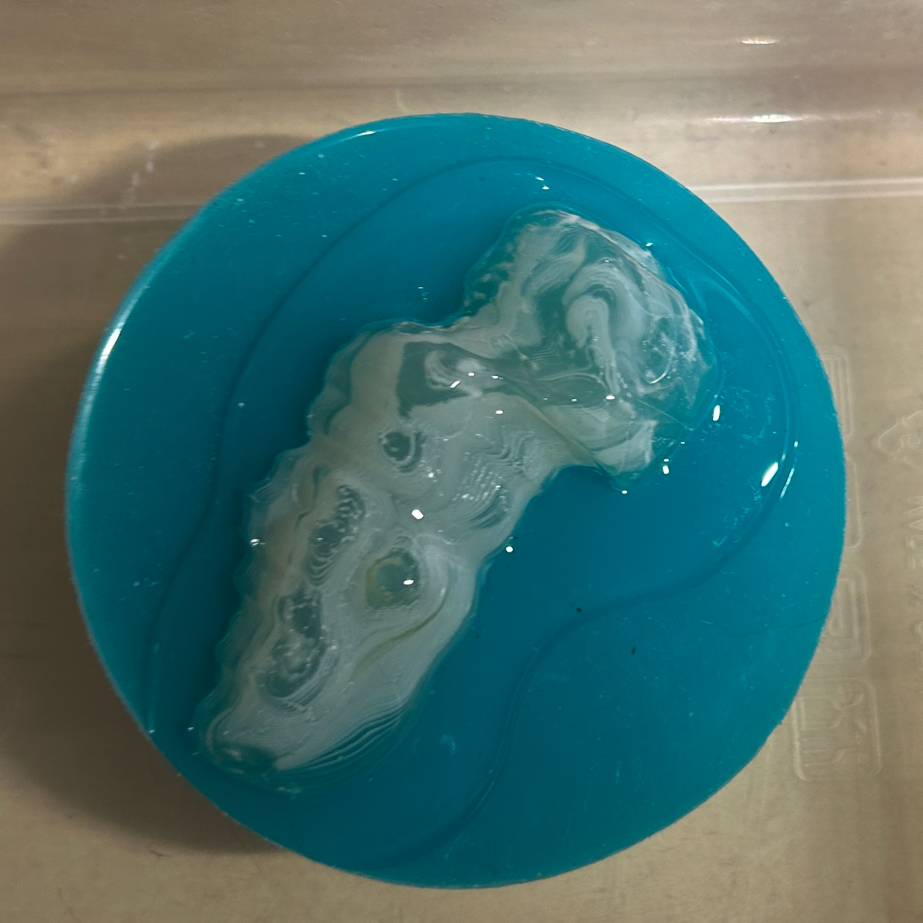
Curing the base layer
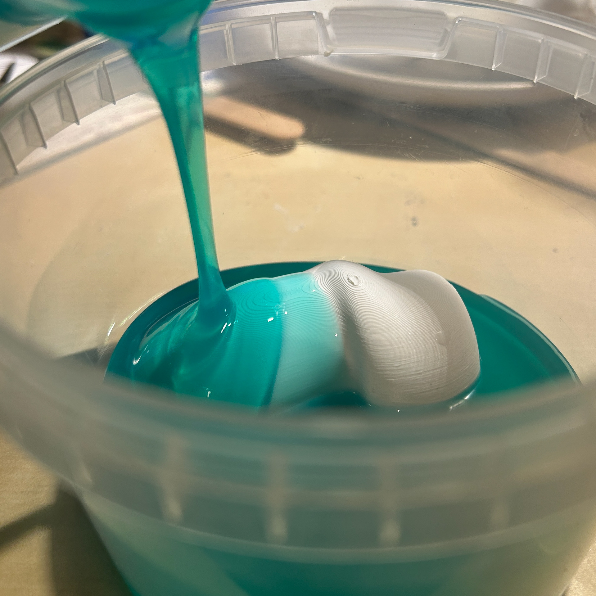
Pouring the silicone
A small air bubble in the silicone mould
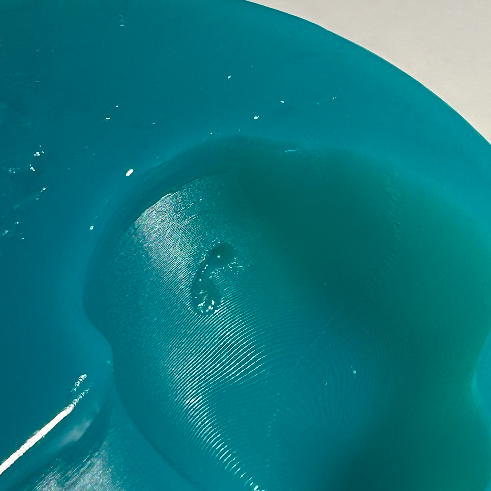
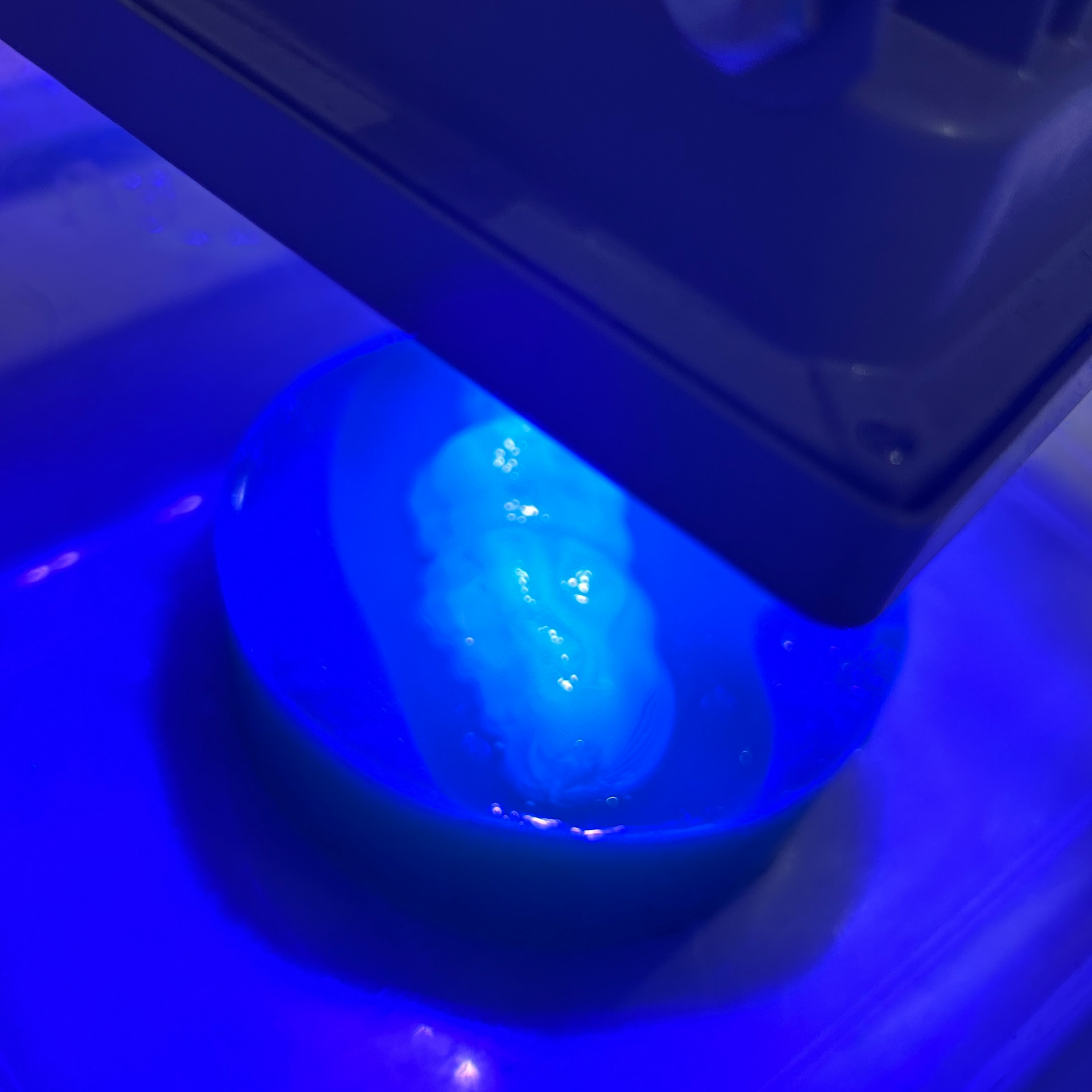
Curing the resin around the agar
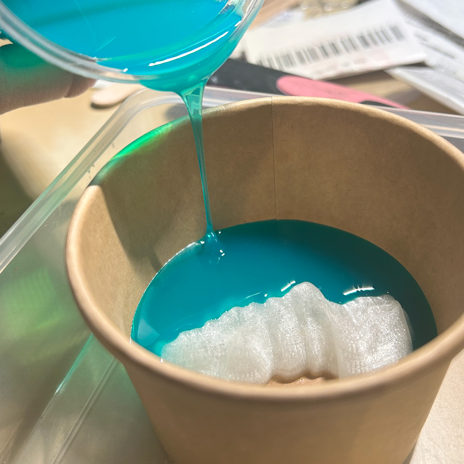
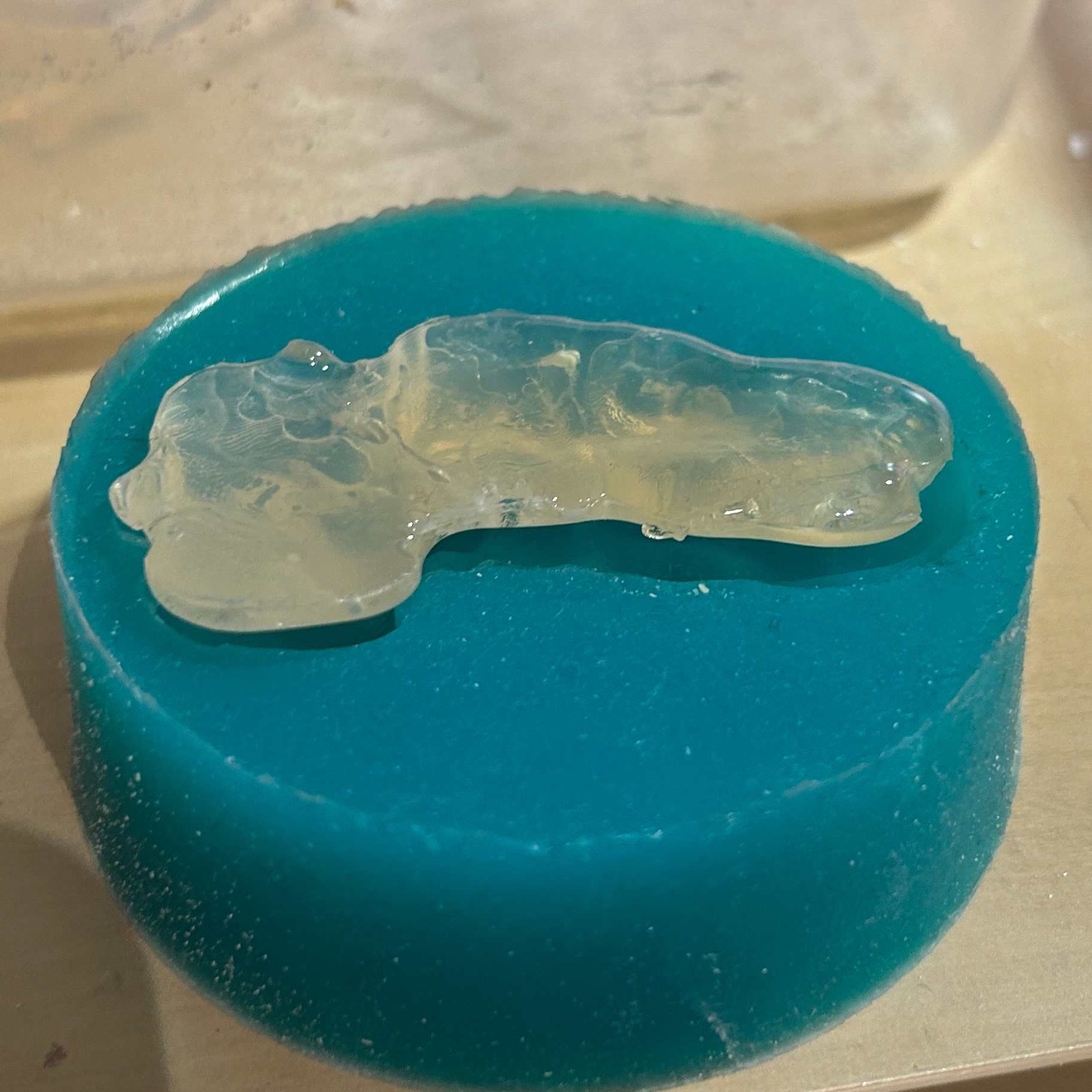
Next, I moved on to creating the silicone mould using techniques I had previously experimented with during Unit X. The first step was levelling the base of the container I was using for the mould. To do this quickly, I applied a 1cm layer of UV resin to the bottom of the plastic container. However, I soon realised that the base was still not completely level. This was likely due to the heat generated by the resin as it cured, which caused slight warping, especially given the relatively thick layer I had applied.
To counteract this issue, I placed the 3D print towards the side of the container where the resin had cured more evenly. While this approach initially resulted in some wasted silicone, it ensured that the mould would work properly in the long run.
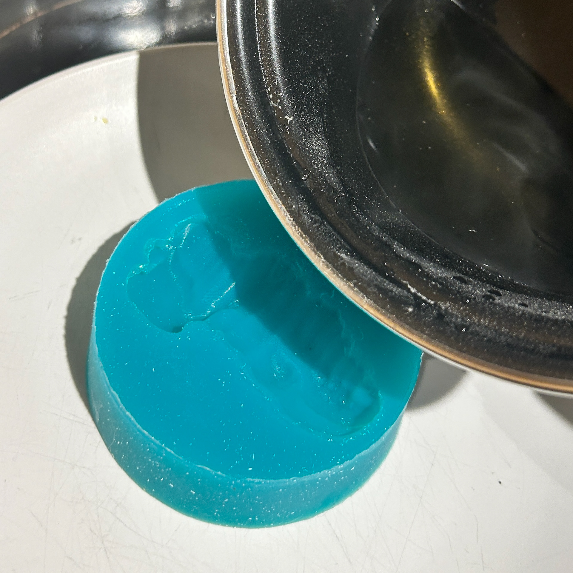
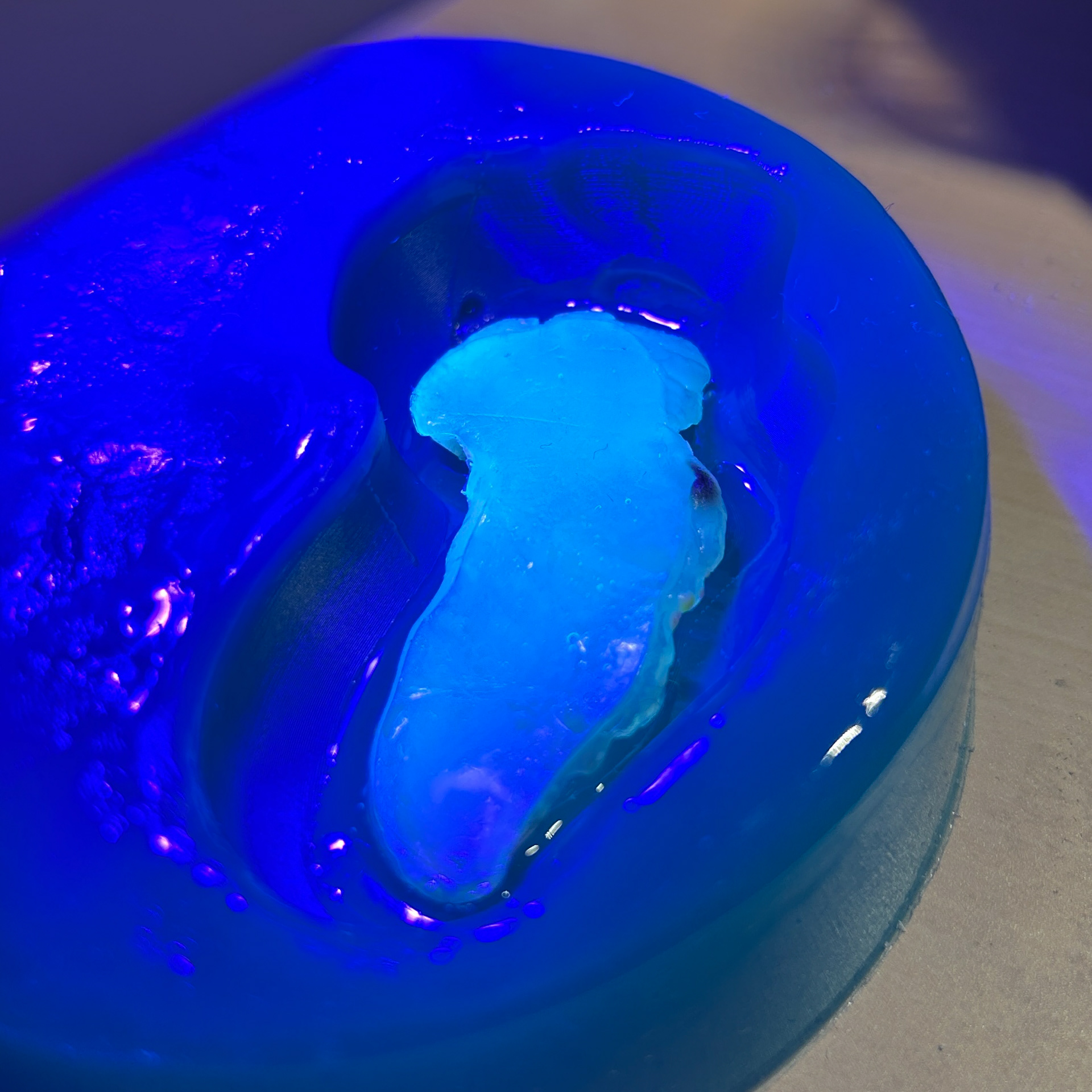
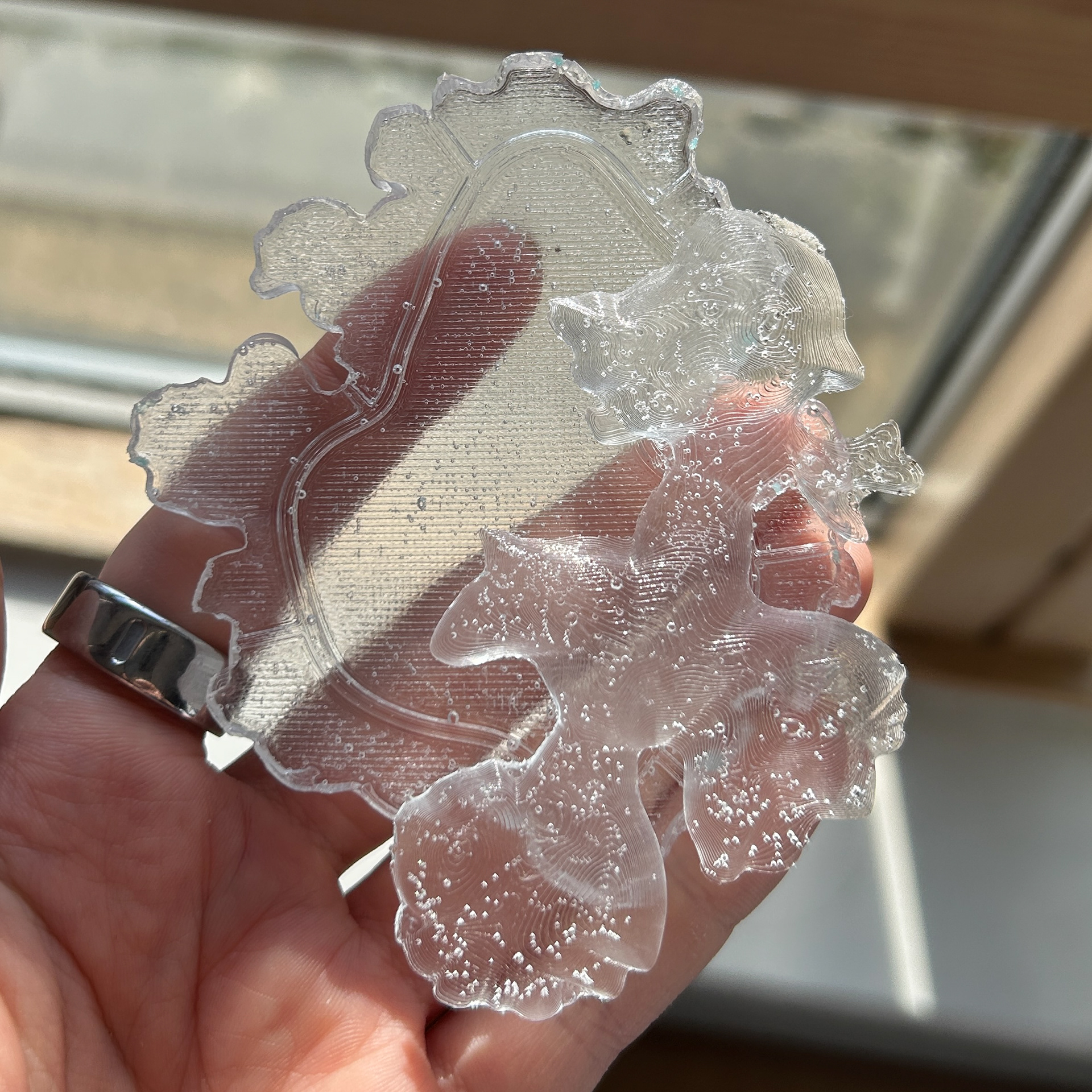
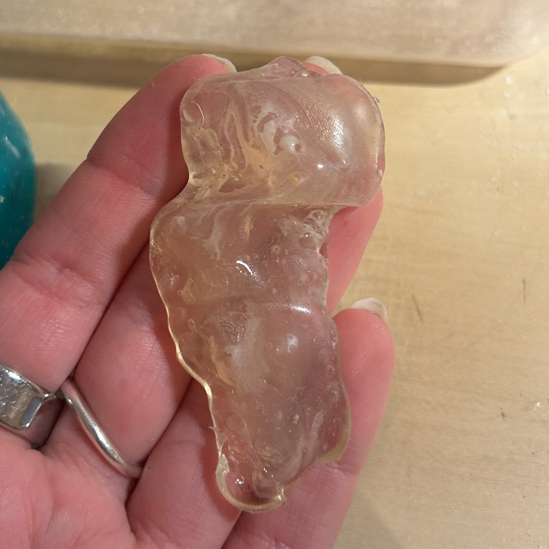
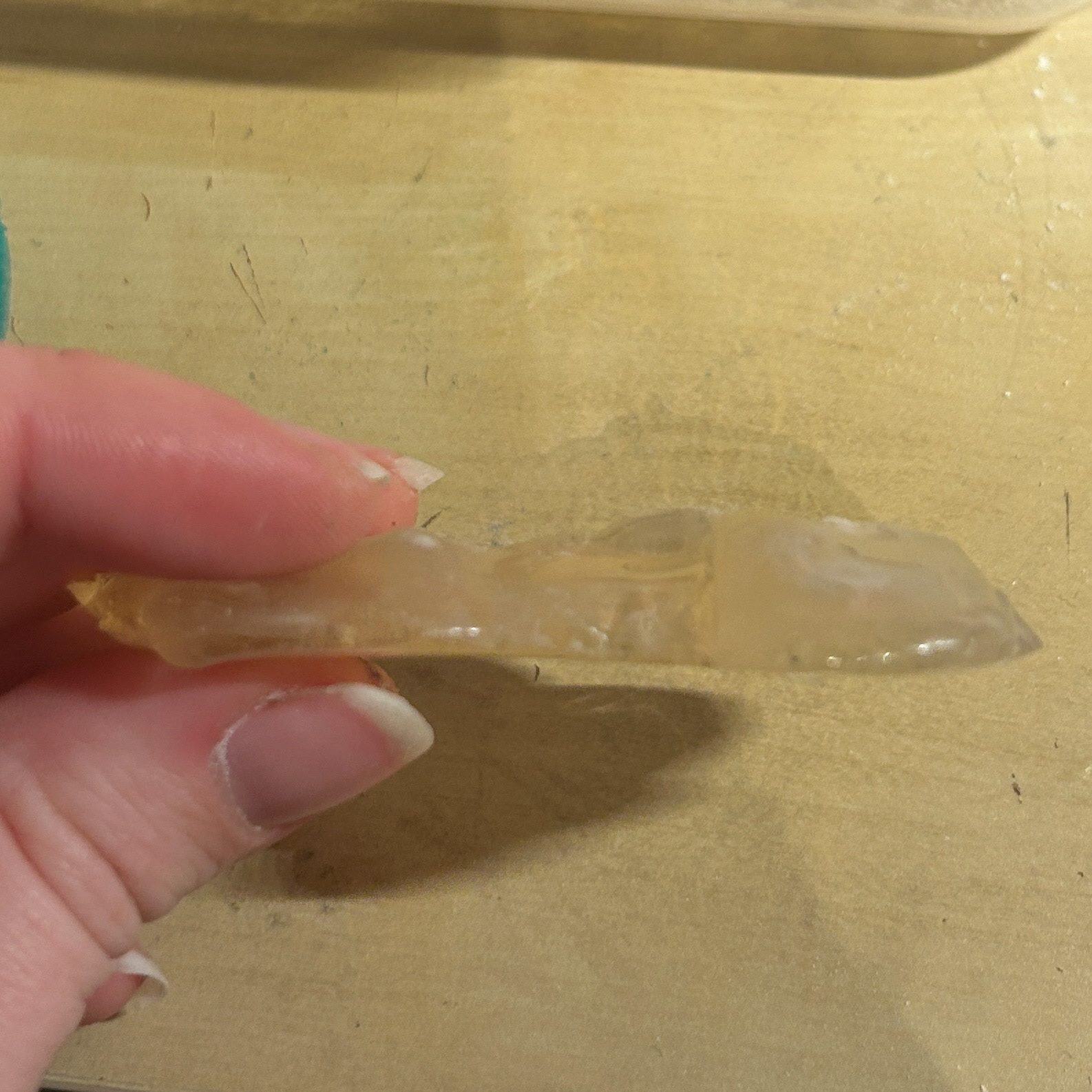
I allowed the silicone to cure for 8 hours before demolding and then left it for an additional 24 hours to fully cure before use. Once ready, I applied the resin using the same method I had used in Unit X. This technique minimised unwanted movement during the curing process, preventing the agar from being left uncovered by resin, an issue I had encountered in my initial attempts during Unit X.
To make sure there was proper coverage, I fully cured the first layer before applying the second layer, waiting approximately 10 minutes to allow the UV resin to settle into any undercuts. I then cured this second layer, followed by a final layer to smooth out the back of the piece.
Although the result was not perfect, this experiment helped me identify several key issues that needed to be addressed, most importantly, the size of the resin mould. I realised that the thickness of the resin surrounding the agar did not need to be as substantial as I had initially thought. This meant I could now return to my CAD models and refine both the agar mould and the resin mould.
Combining Rhino and Blender
11th February 2025

Learning from my previous attempt at making a silicone mould, I decided to combine both Blender and Rhino. I used Blender to create the shape for the agar, allowing me to achieve the smoothness I wanted. Then, I exported this as an FBX file for Rhino.
In Rhino, I traced around the shape and used the Sweep2 tool to make the outer form for the resin. This outer shape was intentionally less complex, making it easier to sand and polish. However, I was concerned that simplifying the resin form might reduce the overall complexity of the piece.
I also found scaling my models easier in Rhino compared to Blender, though this was purely a personal preference.
This sample was created while my original 3D agar sample was still growing, which is why the boundaries around the agar were still quite thick. I found that these pieces were still quite thick, and would essentially be a chunk of resin, which is not what I wanted. While it was annoying to have these outcomes not be what I wanted, I understand that it is an important part of the process.
Combining Rhino, Fusion, and Blender
13th February 2025

After my tutorial with Patricia, I decided to write down what it was about my 3D prints that I did not like. Having the problems down on paper meant that I could visualise the problems that I needed to address.
My main issue was that the shapes were losing the complexity that I liked when I was making them in Blender, however, I was losing the smoothness when I was using Rhino.
Both programs had their pros and cons, but I questioned if I could continue to combine the two.
Instead of using Blender to make the shapes, could I use them to soften the ones I made in Rhino? While this would be making the time scale of making the objects longer, was it the answer to getting the perfect shapes that I wanted?
I found that I could export my Rhino files as OBJ files and import these into Blender, meaning that I would be able to edit the mesh.
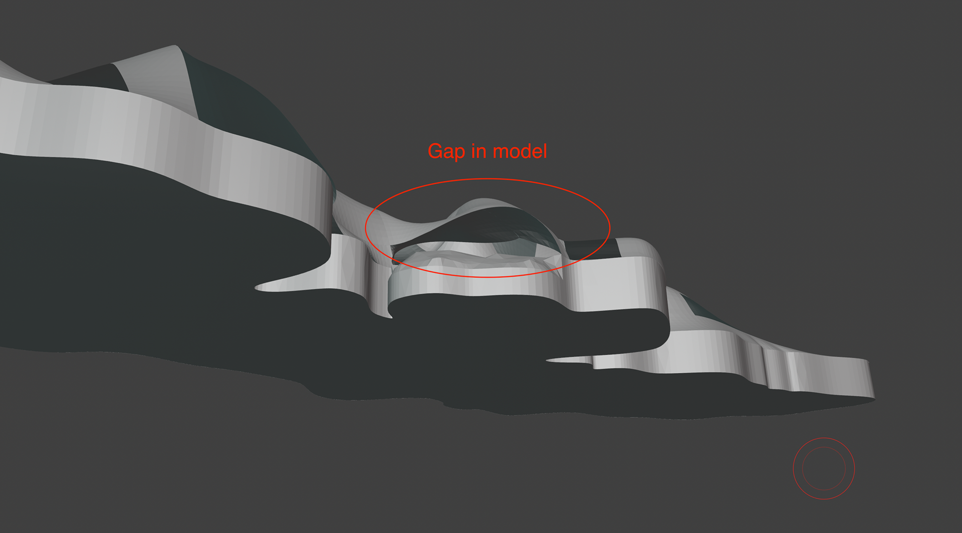
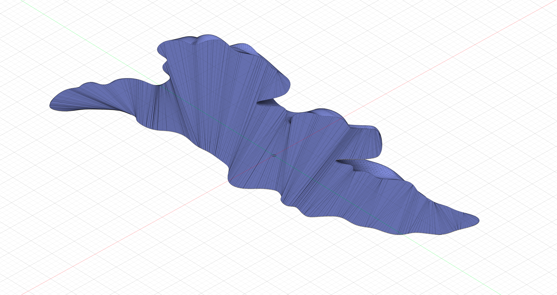
I tried this with the Rhino shape that both Patricia and myself thought was the best one, however I found a problem straight away. While I was able to smooth the mesh easily, it opened up gaps between the organic shape that I had made and the capped base that I had added. I added this base to not only add height but also because I was unable to cap the organic shape. This meant it had to go back into Rhino and fix the poor modelling that I had done.
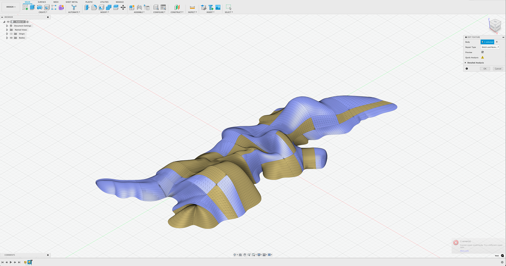
I moved back to Rhino and attempted to cap just the organic object, and in hindsight, the base was not needed anyway. However, when I went to cap the shape I kept getting error messages saying that the shape was not a closed curve. I needed to see if what I was doing was actually the correct way to do it, so I tested it with a simpler shape and it worked, so I knew it was a problem with the model itself.
I spent a very long time trying to work out why the shape was not capping and eventually gave up and tried to cap the object in a different way.
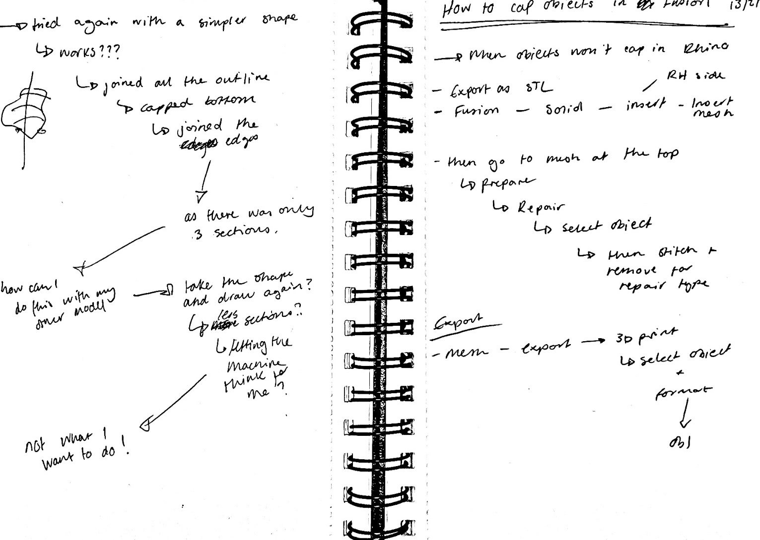
I moved the object into Fusion, and capped it there instead using the instructions above. This took a lot of trial and error but it finally worked.
I understand that this is a very long-winded way of capping the object, however trying to use Rhino to do it was not working.
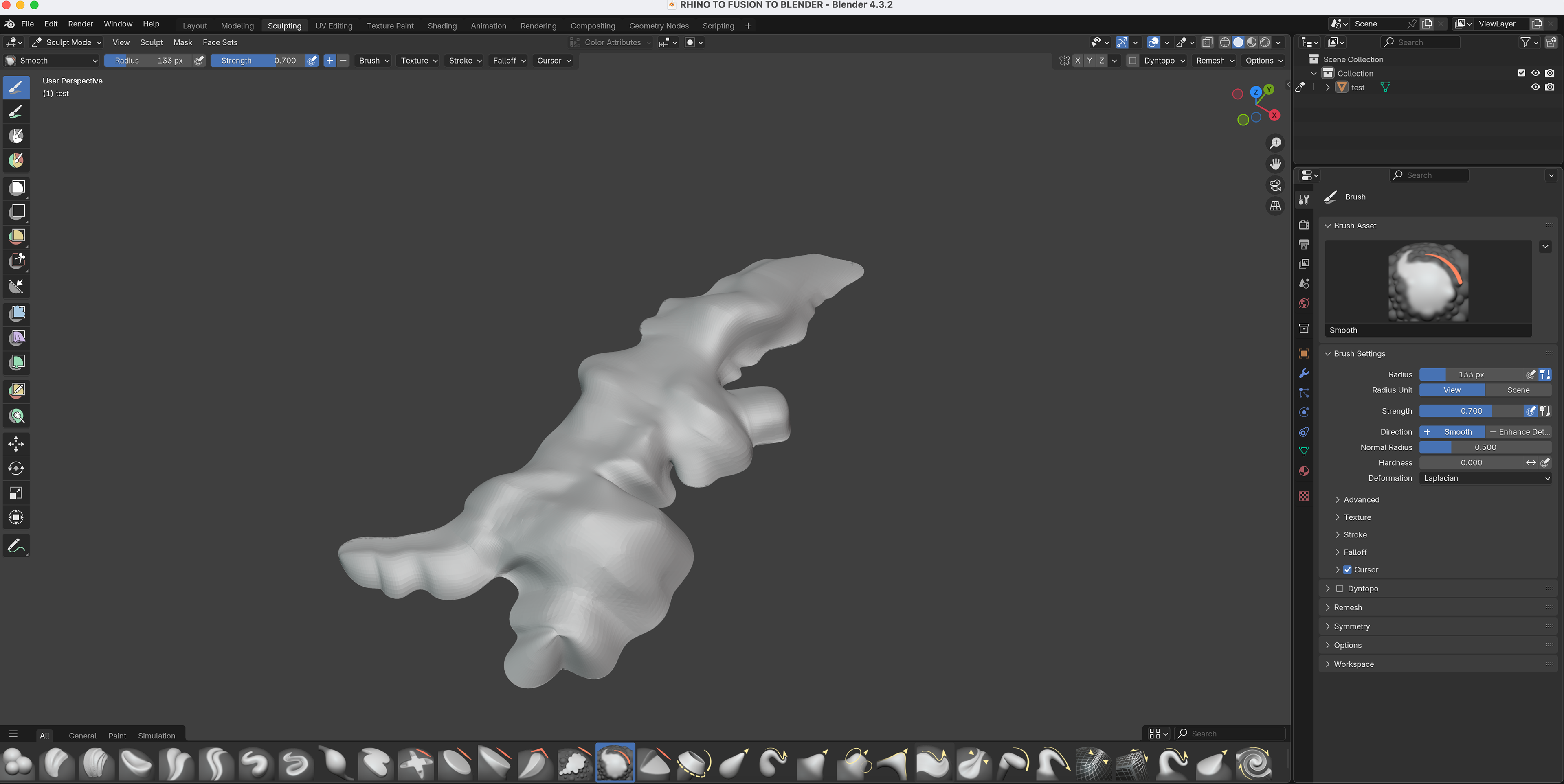
After smoothing the object in Blender
I then printed the shape and went in with sanding paper to create the smooth surface that I wanted.
I was much happier with this sample, as it was complex while still being smooth. From now on, I will be using Rhino and Blender to make my CAD models.
Laser Cutting Experiments
19th February 2025

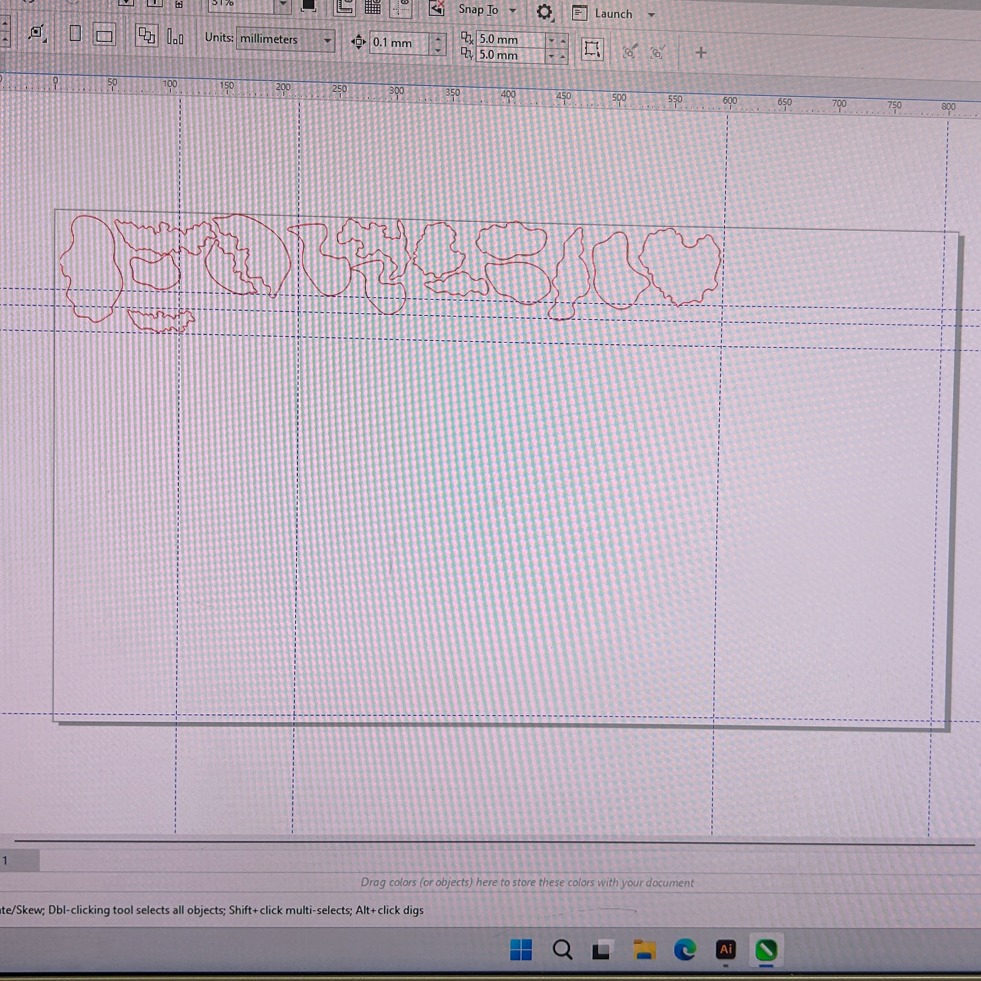
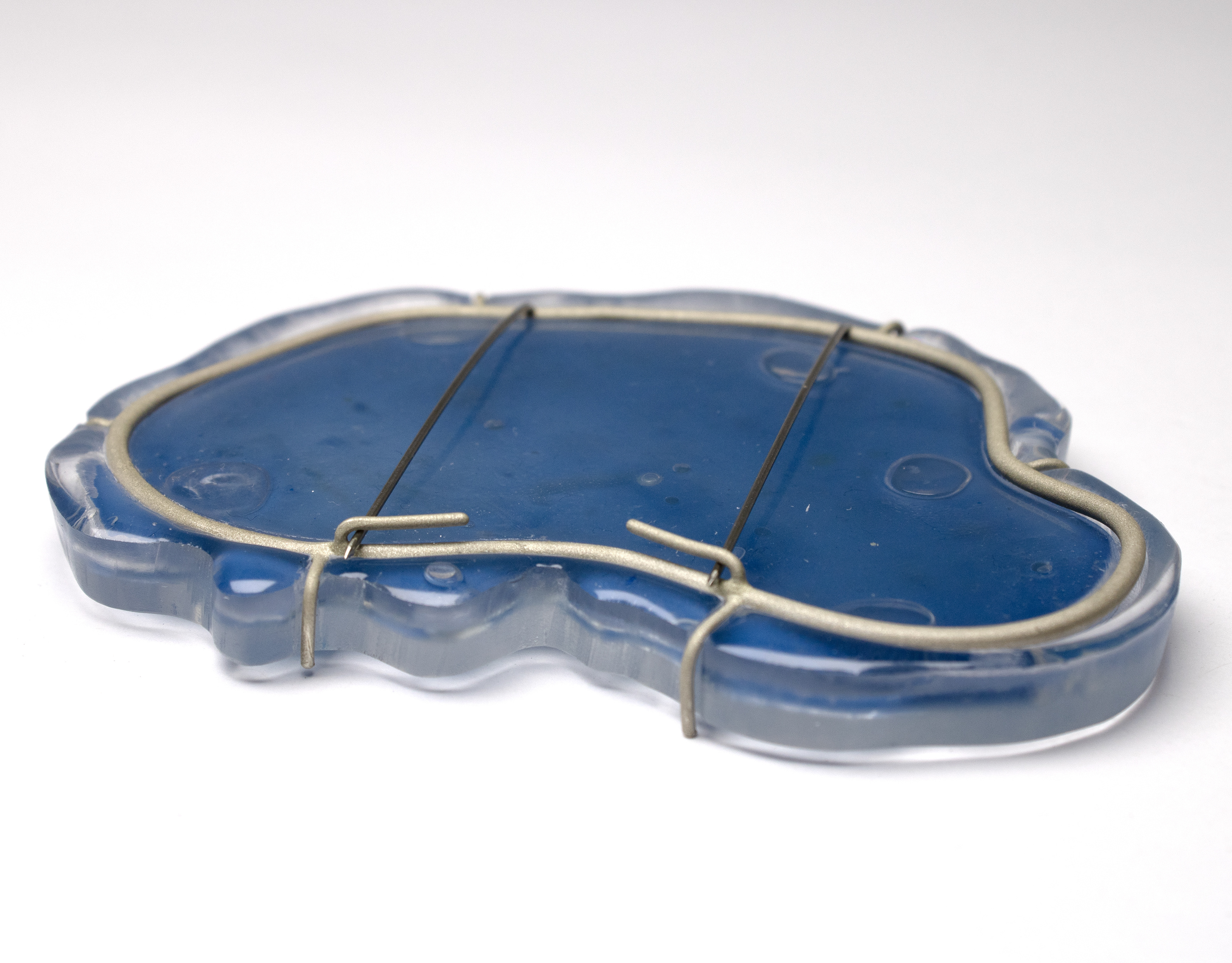
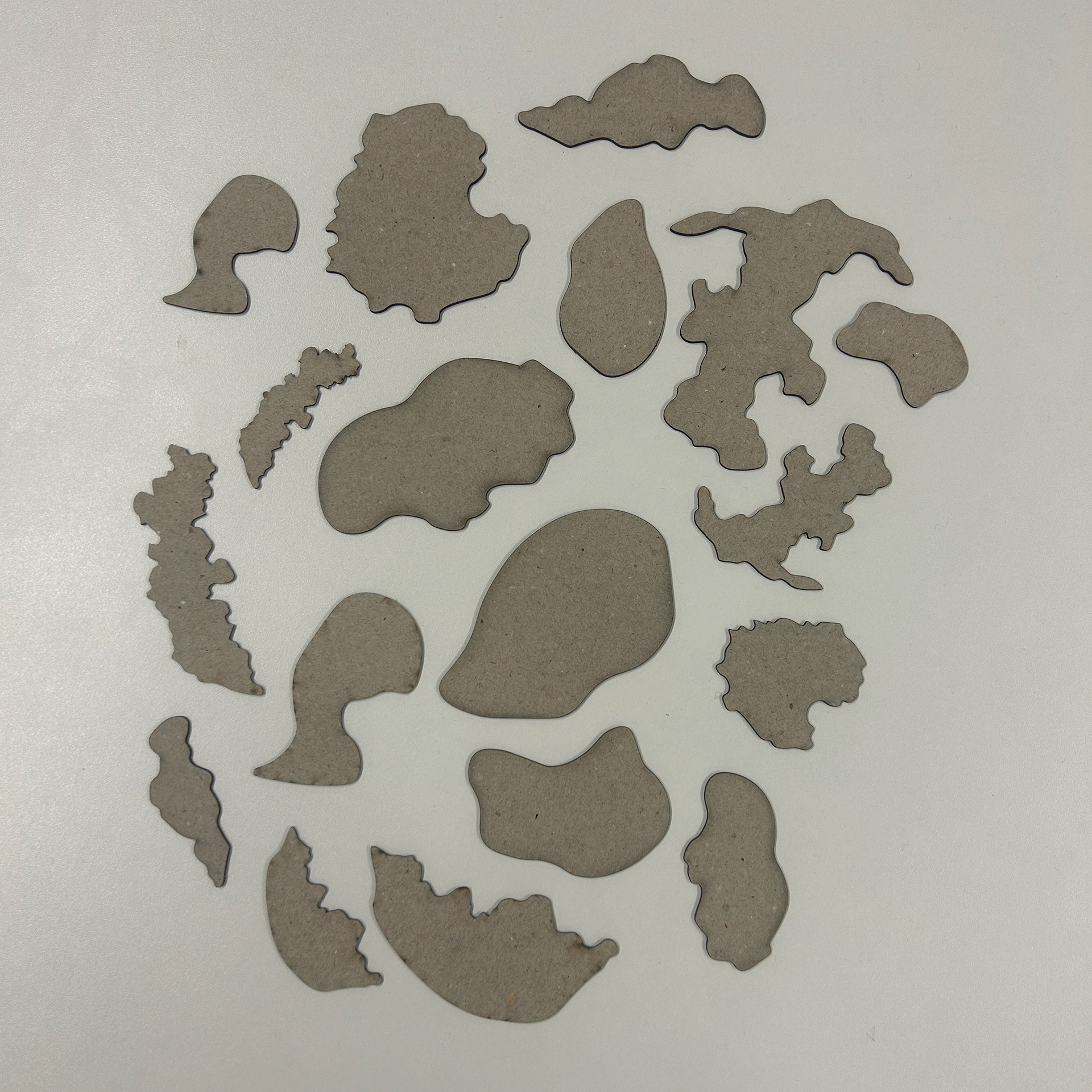
After my tutorial with Patricia, where we discussed how lost I was feeling with the project at this stage, I decided to take a more hands-on approach by laser-cutting shapes that could resemble the back plate. I started by sketching out my designs in Adobe Illustrator, using the bacteria growth patterns I had previously worked with in Rhino.
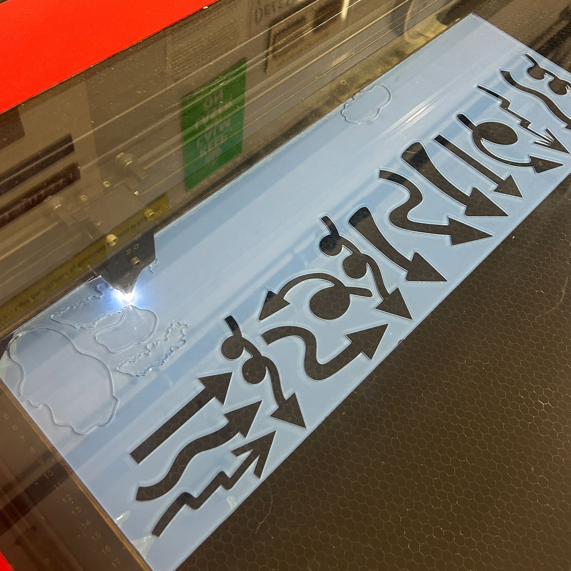
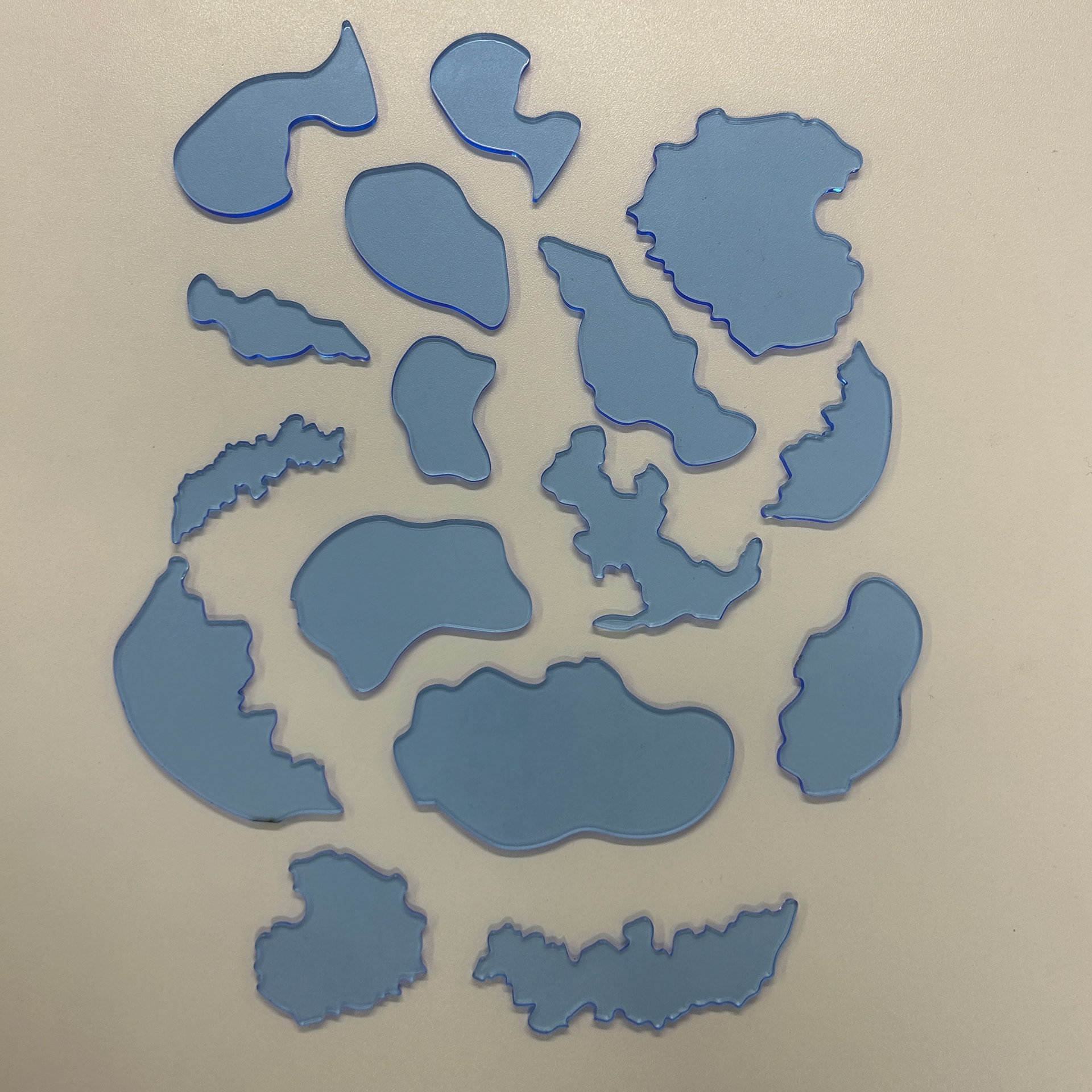
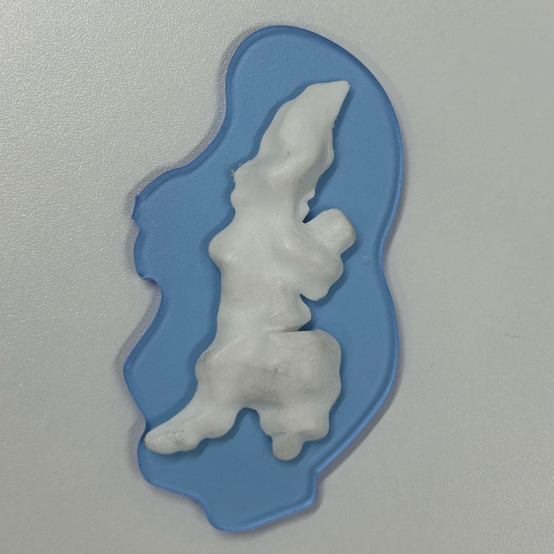
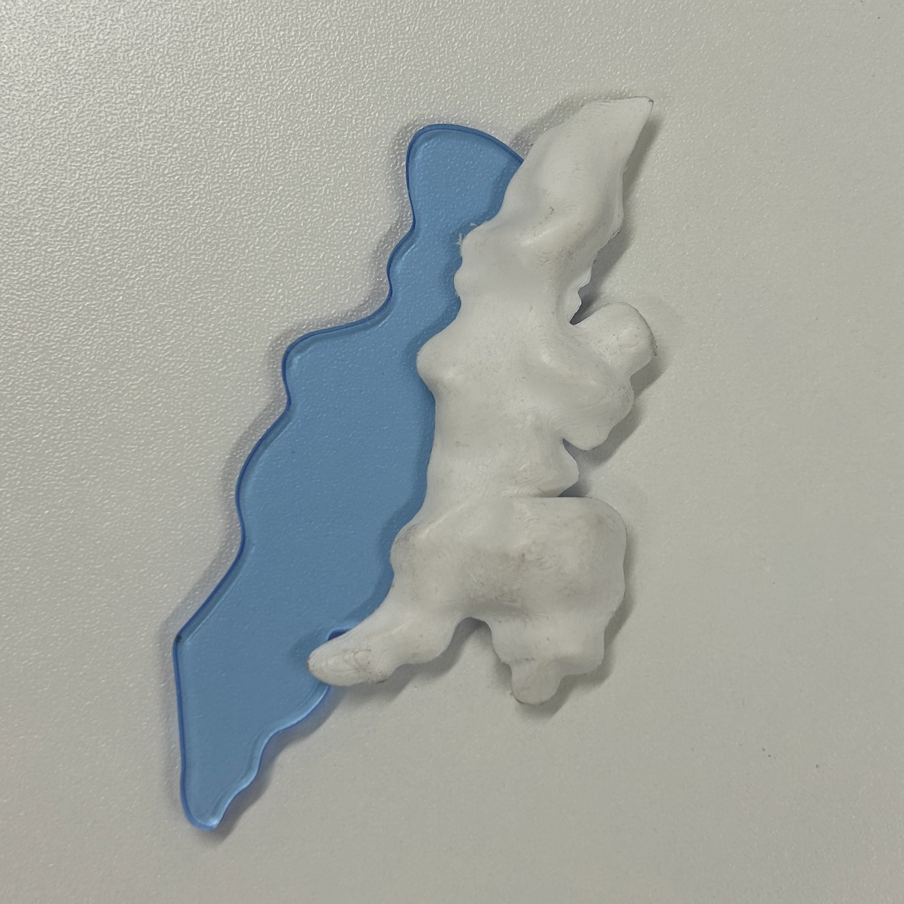
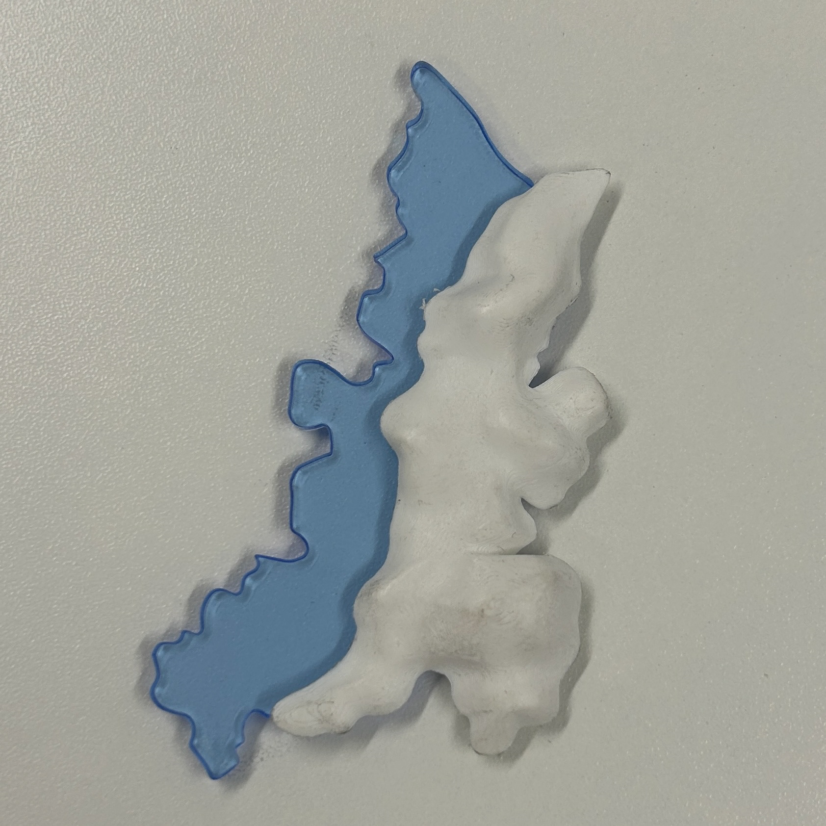
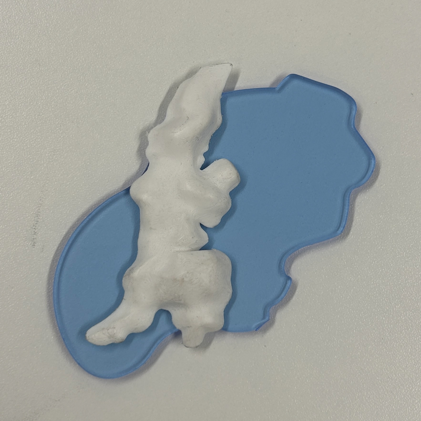
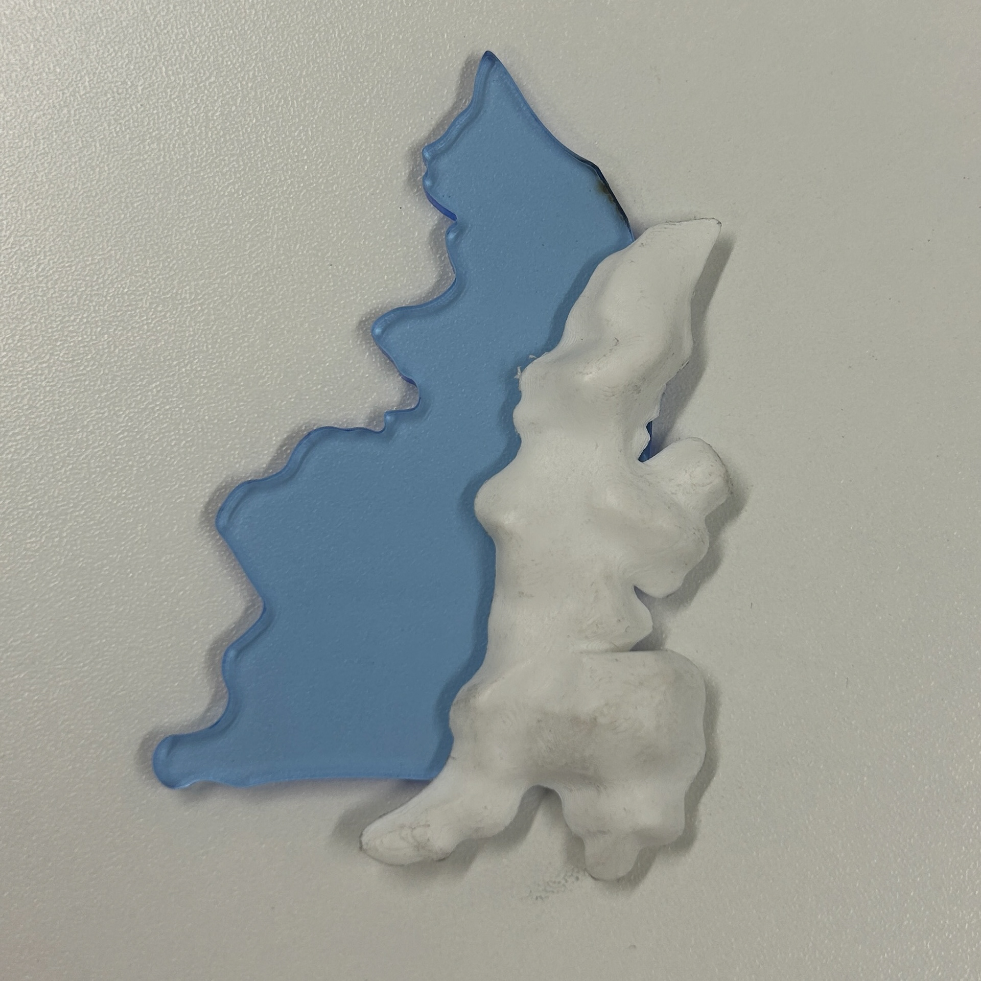
To test the scale, I first cut the shapes out of greyboard, allowing me to check the proportions and make any necessary adjustments. Once I was happy with the scale, I moved on to cutting the final shapes using transparent blue acrylic. I specifically chose this blue colour to match the Potato Dextrose Agar I had ordered for the back plates, which was supposed to have a light blue tint. Using the blue acrylic helped me visualise how the final piece might look when combined with the 3D agar.
The Laser Cuts
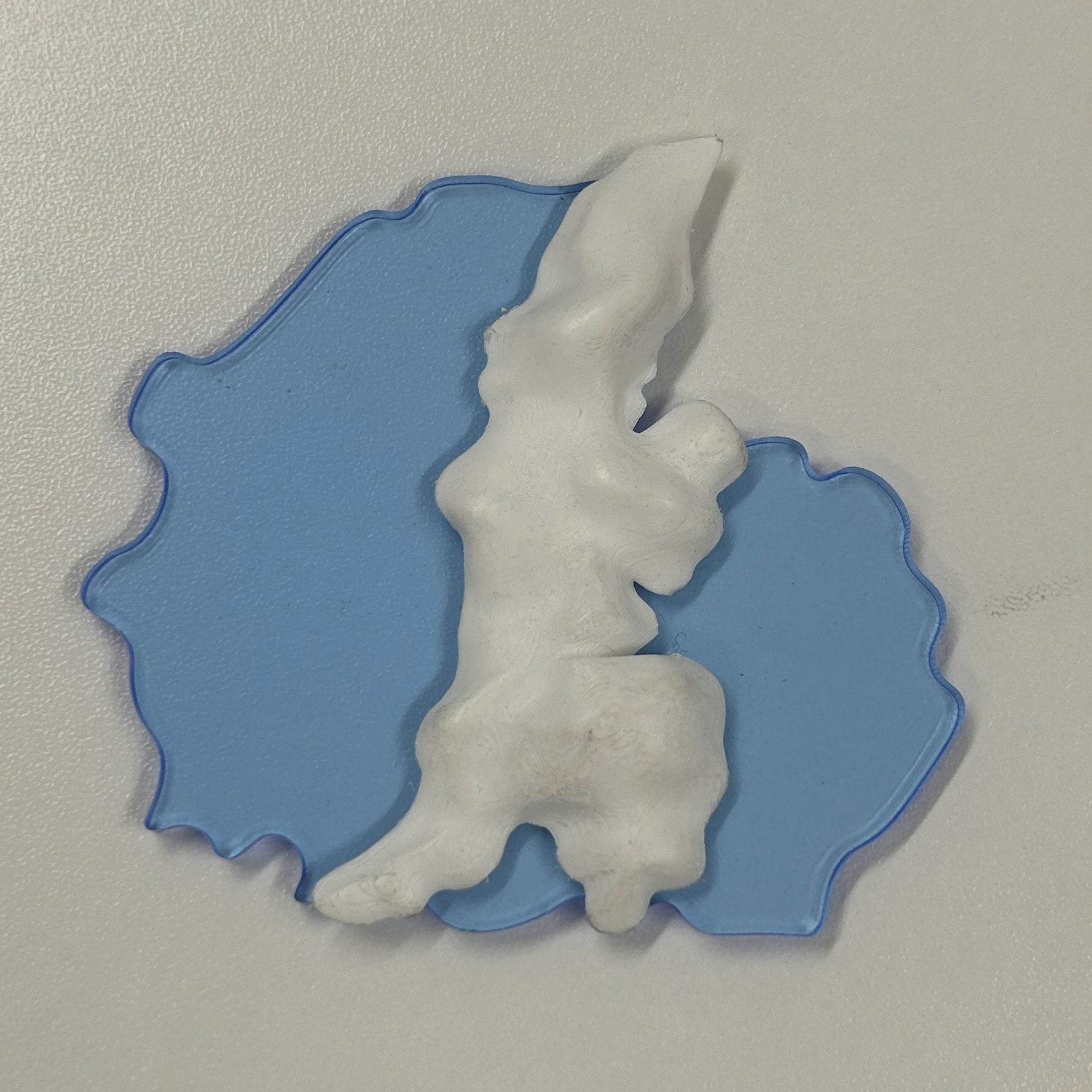
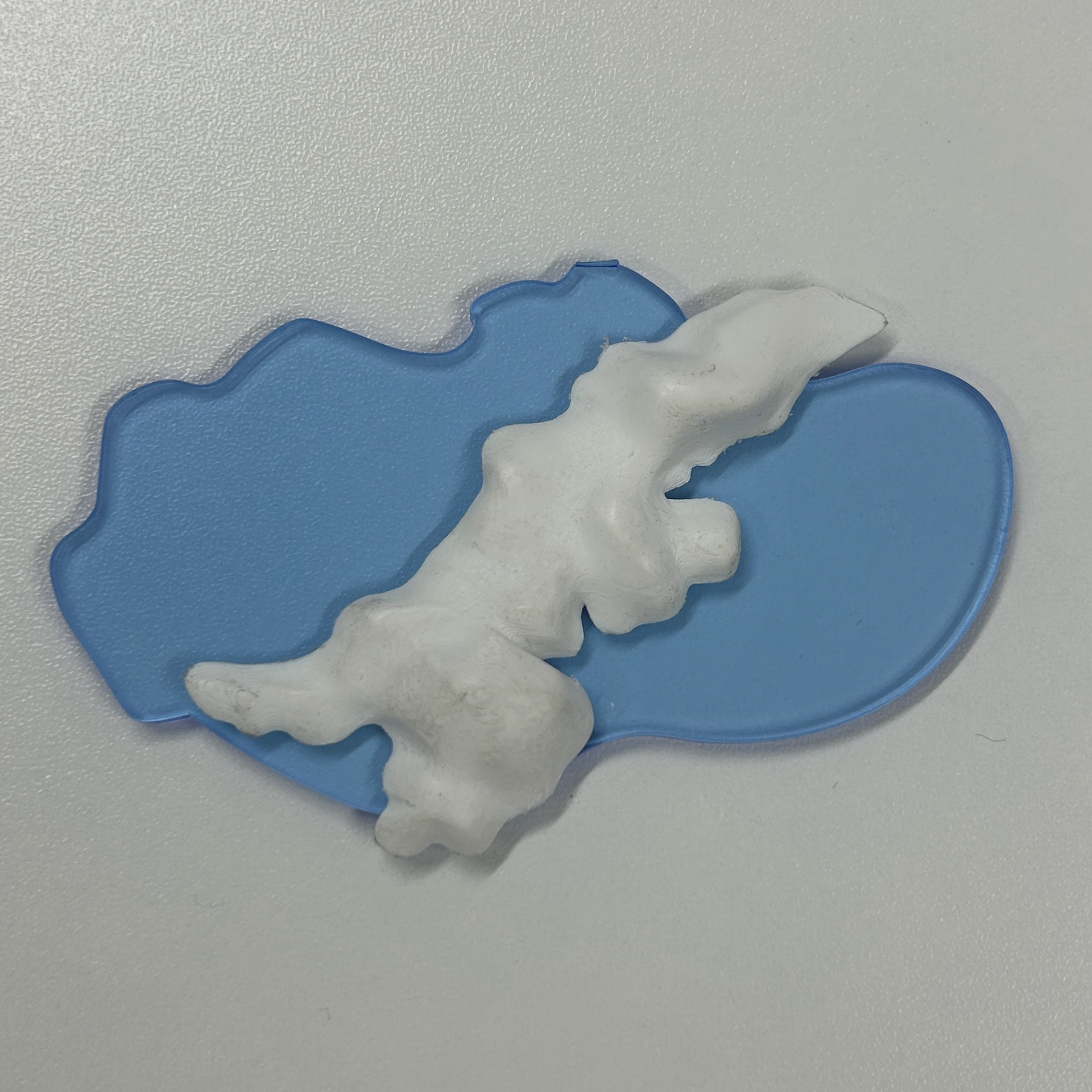
Experimenting with Compositions
I then used my 3D print using Rhino, Fusion, and Blender to experiment with different compositions. While a very basic technique, I really enjoyed exploring the different combinations, it gave me the chance to visualise what the final object could be which is what I needed.
Testing a New Agar Powder
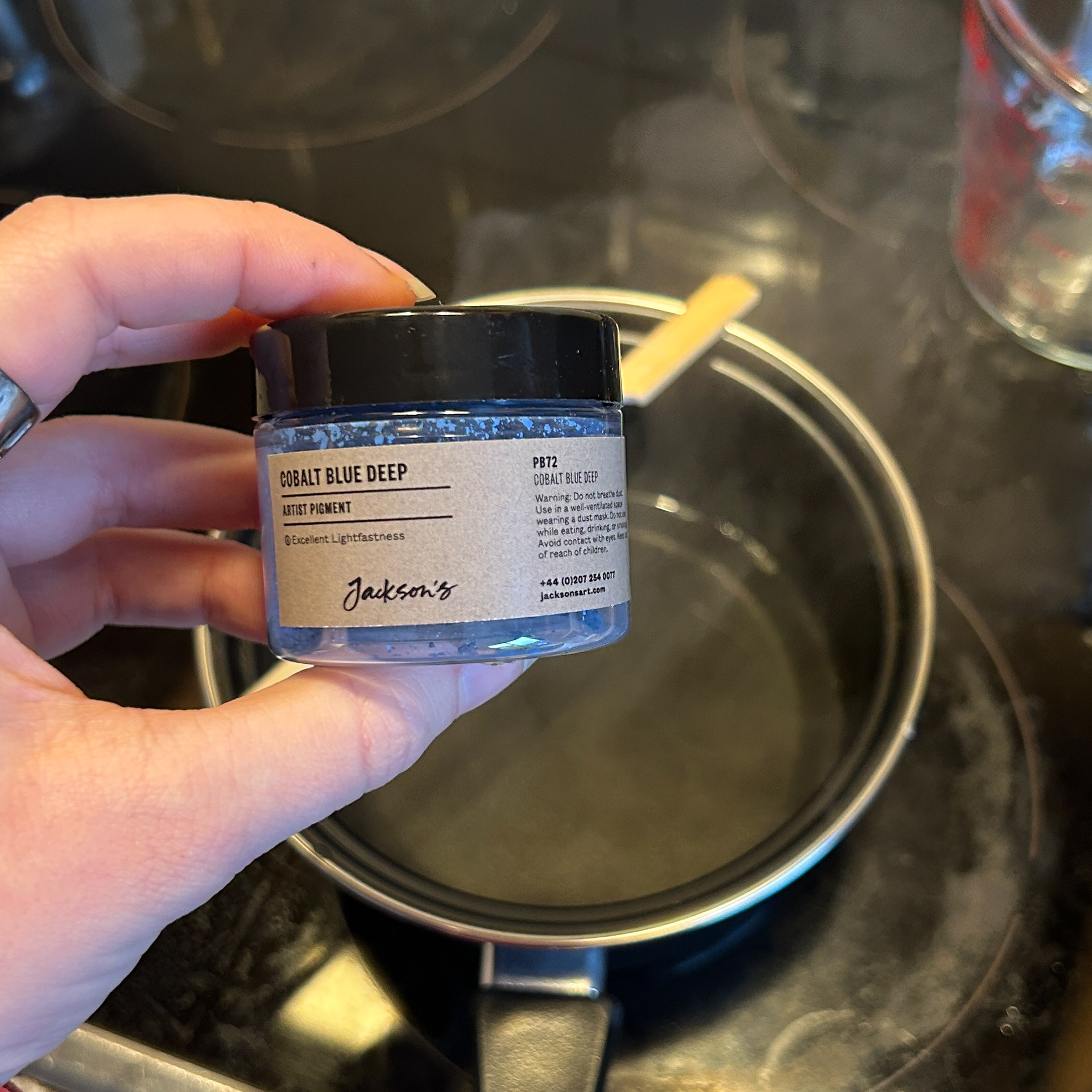
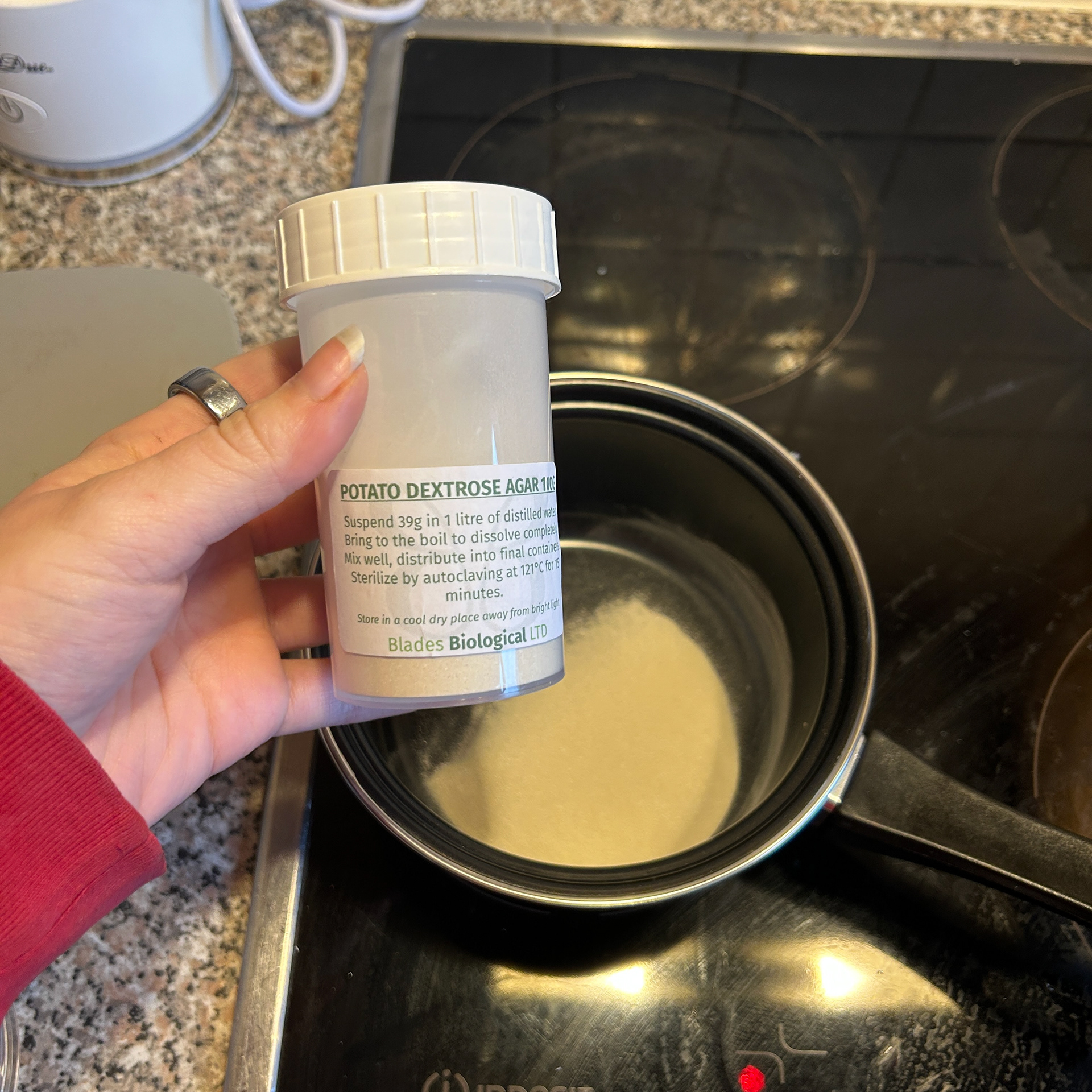
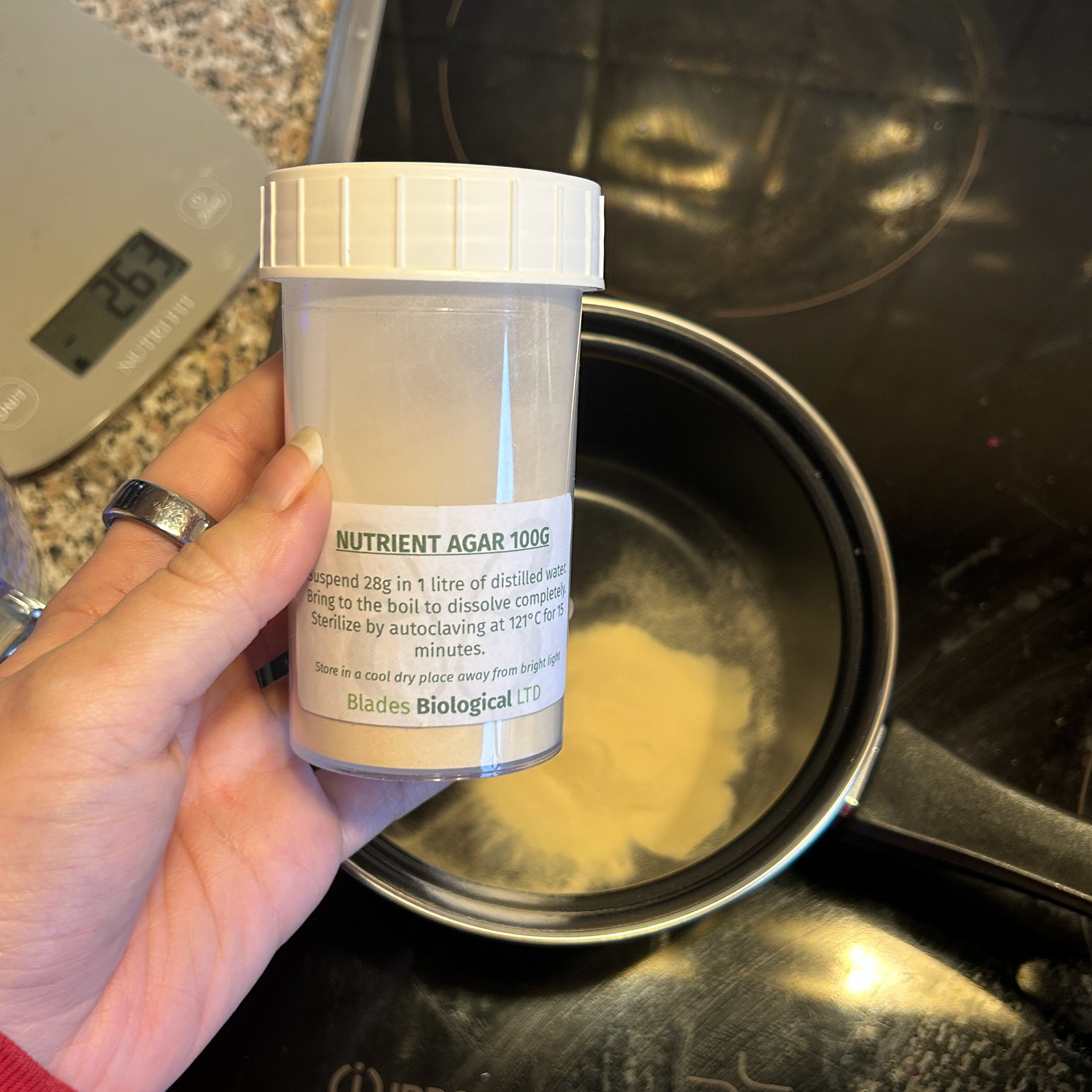
To continue with my bacteria experiments, I needed to prepare more petri dishes. This time, I decided to use both the standard nutrient agar and a new growth medium, potato dextrose agar. From what I had read, the potato dextrose agar was supposed to have a slight blue tint compared to the nutrient agar. However, I wanted to ensure that the colour difference was more distinct, so I ordered some cobalt blue pigment powder as a backup in case the natural colouration was too subtle. I was also hoping that this pigment would be less likely to fade like the colour examples I had done during the Beta Project with food dye.
Once I made the potato dextrose agar mixture and poured it into several 100mm Petri dishes, I found that the blue tint was much fainter than I had anticipated. Since I wanted a more noticeable contrast, I decided to experiment by adding a small amount of the blue pigment to some of the plates.
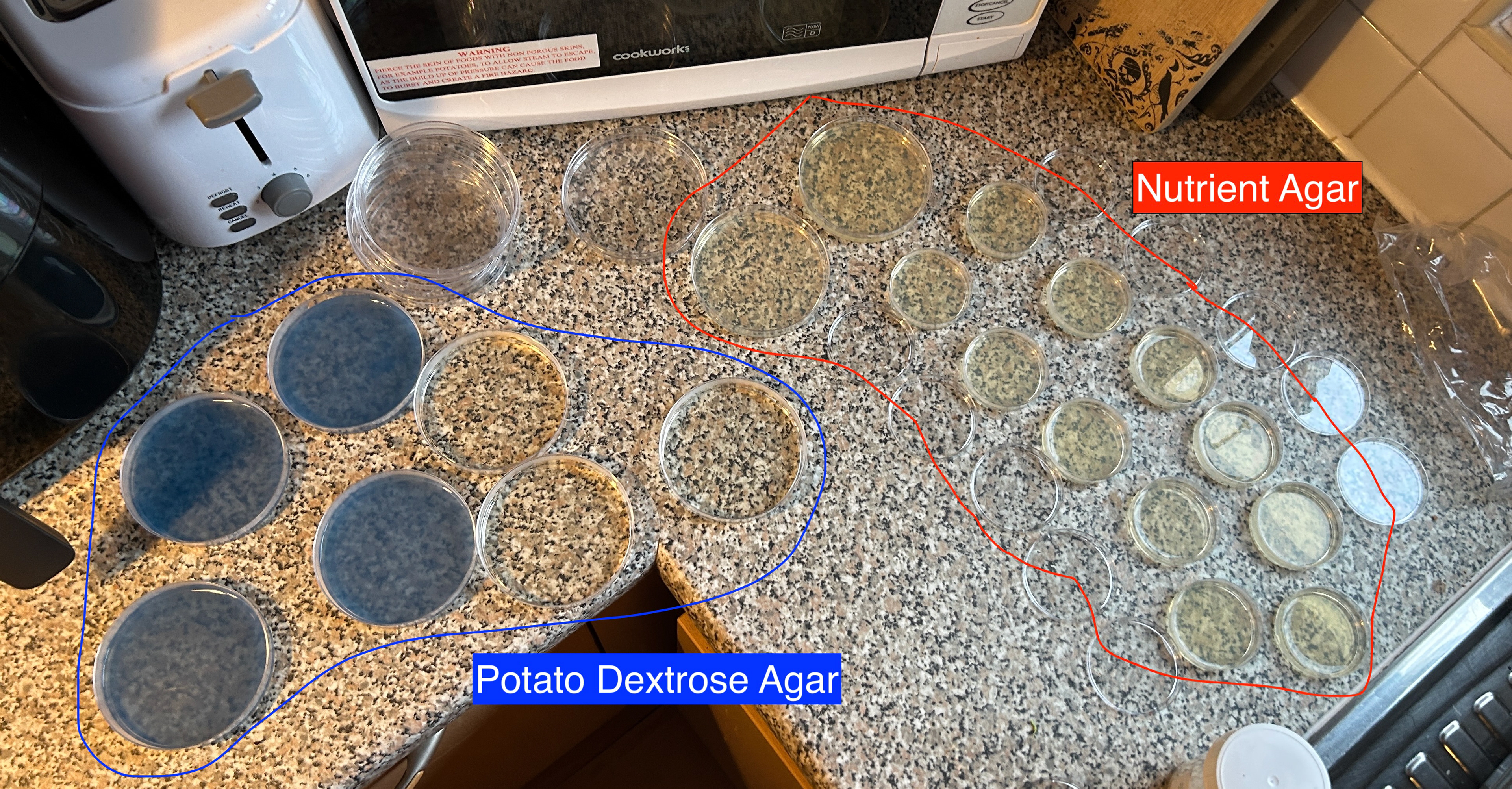
After allowing the plates to cool and solidify, I noticed an interesting effect. The ones with the added pigment had turned slightly more opaque than the unaltered potato dextrose agar. While I personally quite liked this effect, with it reminding me of Leonie Damm’s work, it wasn’t necessarily the result I had originally aimed for. The opacity might impact the visibility of bacterial growth, which is crucial for my experiments.
The next step is to add the swabs to the plates and observe how bacterial colonies develop on both the natural and the pigmented agar. I am particularly curious to see whether the added pigment affects the growth patterns or if it enhances or hinders the visibility of bacterial formations. This unexpected variation has opened up a new layer of experimentation, and I am excited to see what the results are, as this could change my design ideas.
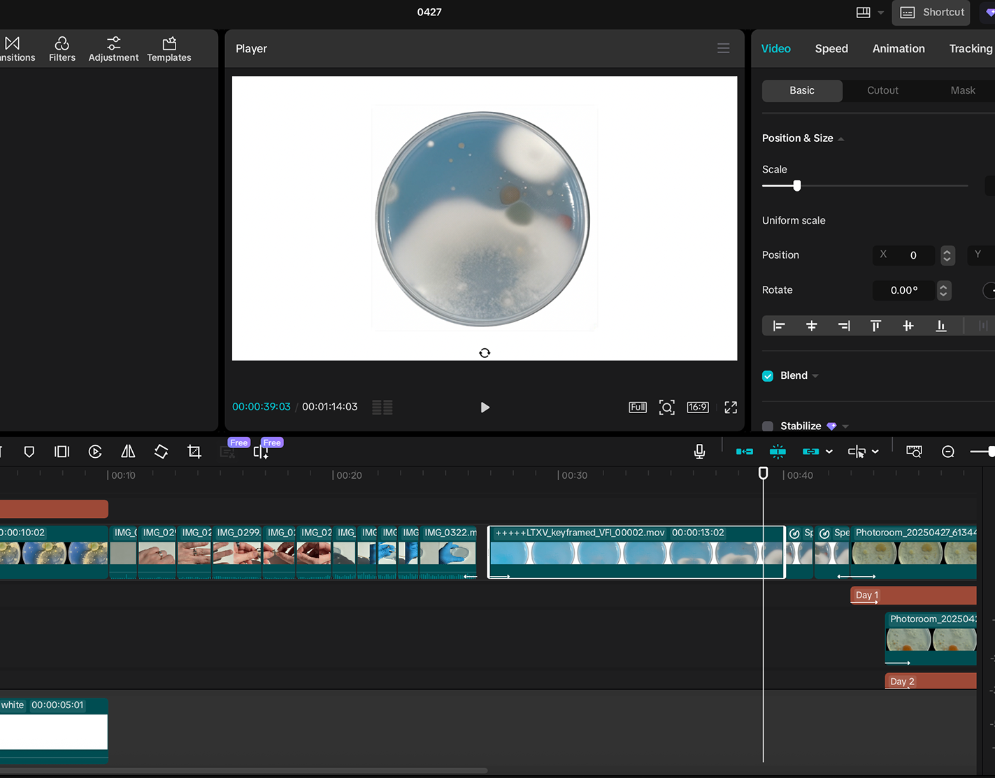
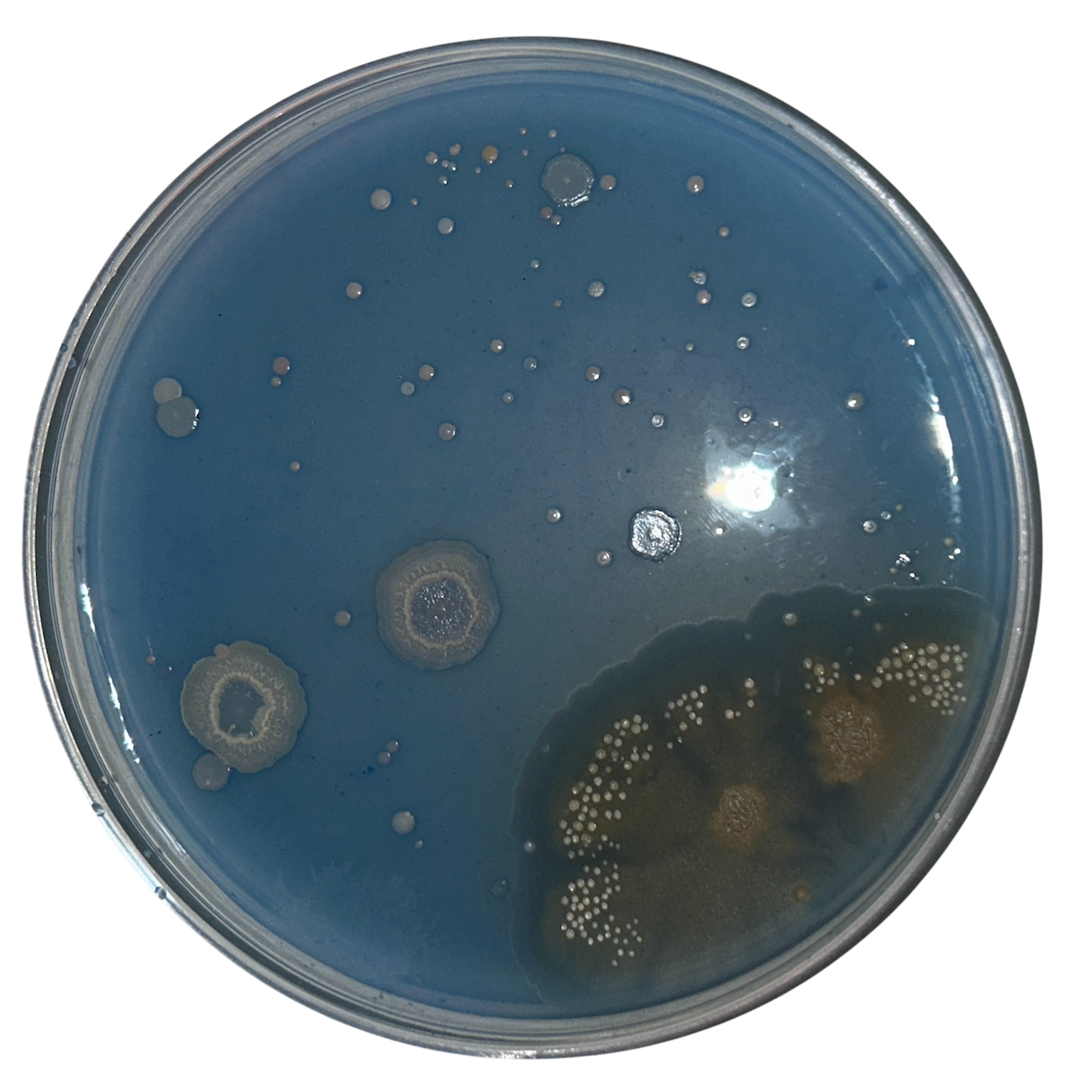
Experimenting with Bacteria and Time
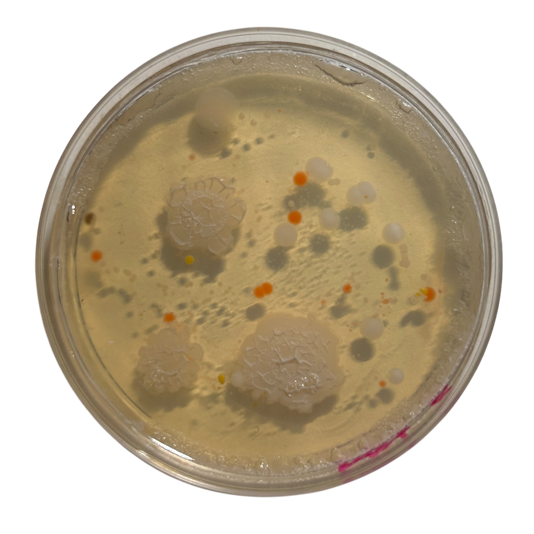
As part of my experimentation, I wanted to explore how bacterial colonies evolve and change over time. To do this, I decided to take a sample from an everyday object, one of my rings, and transfer the bacteria onto four nutrient agar plates. This would allow me to monitor the progression of bacterial growth and observe any interesting changes.
After swabbing the ring and inoculating the plates, I checked them daily for signs of bacterial development. Initially, there was little to no visible growth, but by days two and three, small bacterial colonies had begun to grow.

Day 3
Day 5

Day 7
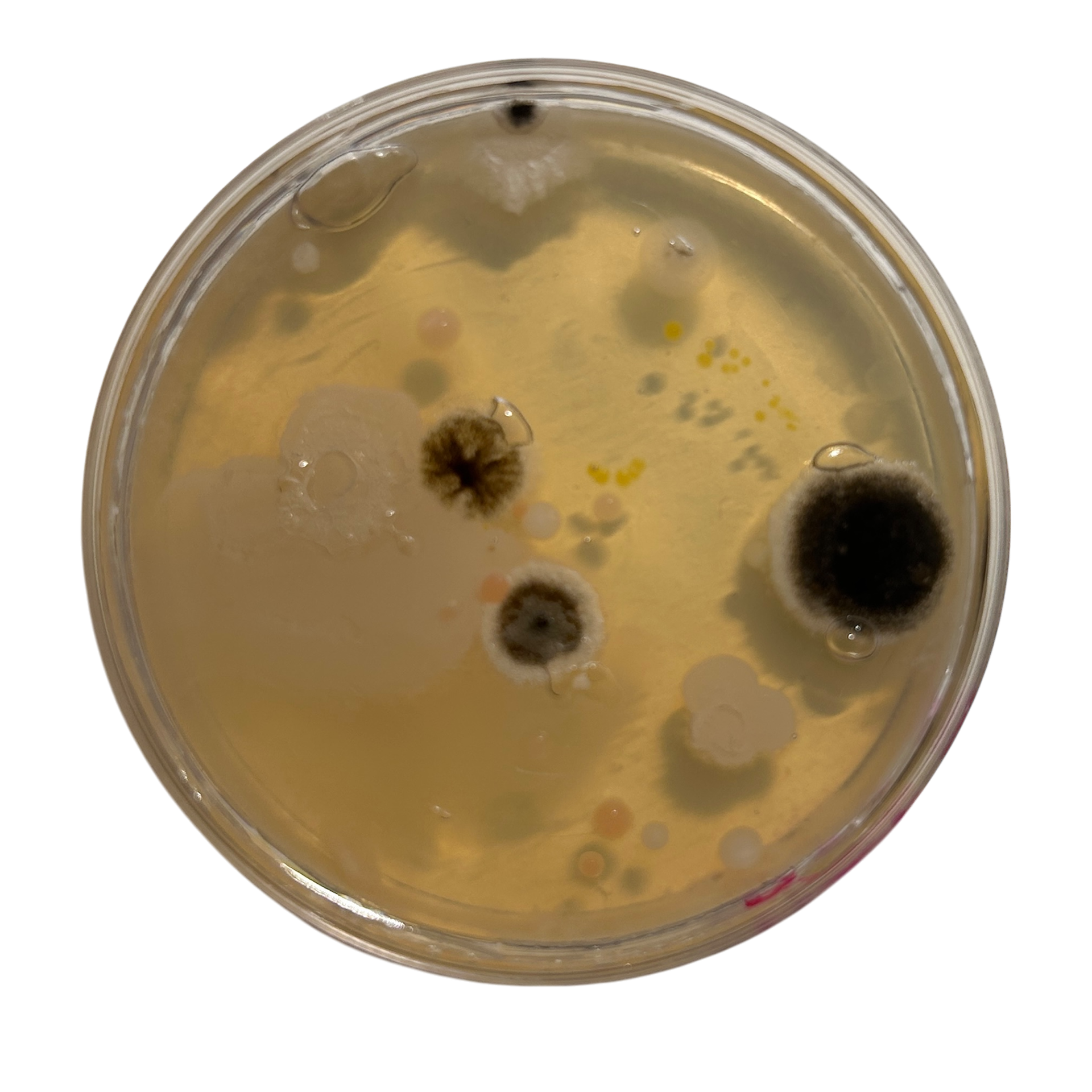
Day 9
To capture the progression of bacterial changes, I selected specific time points (days 3, 5, 7, and 9) to preserve the plates. At each of these stages, I removed a plate from where it was growing and covered it with resin, effectively halting any further bacterial growth. This method allowed me to create a series of preserved snapshots, each representing a different stage in the bacteria’s life cycle.
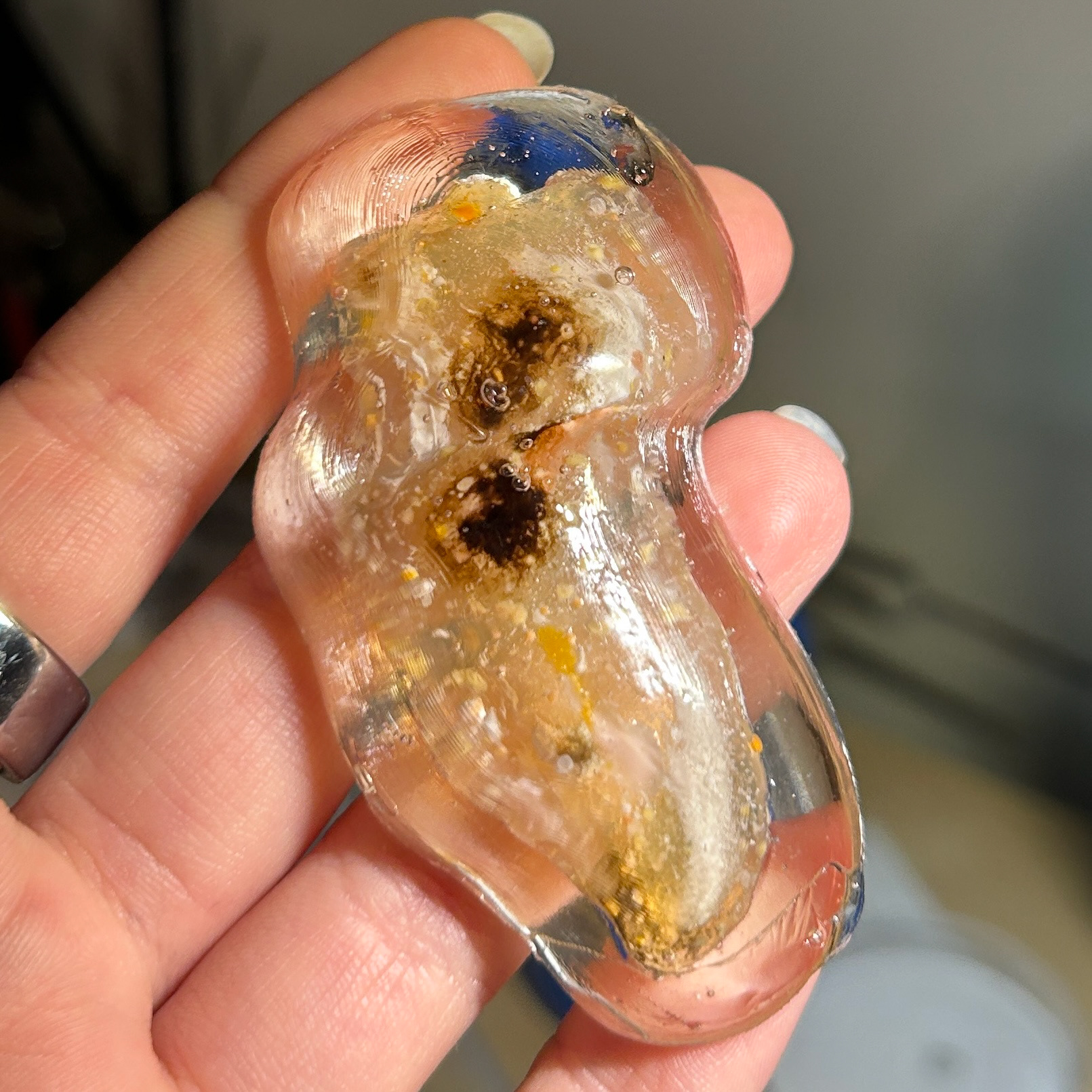
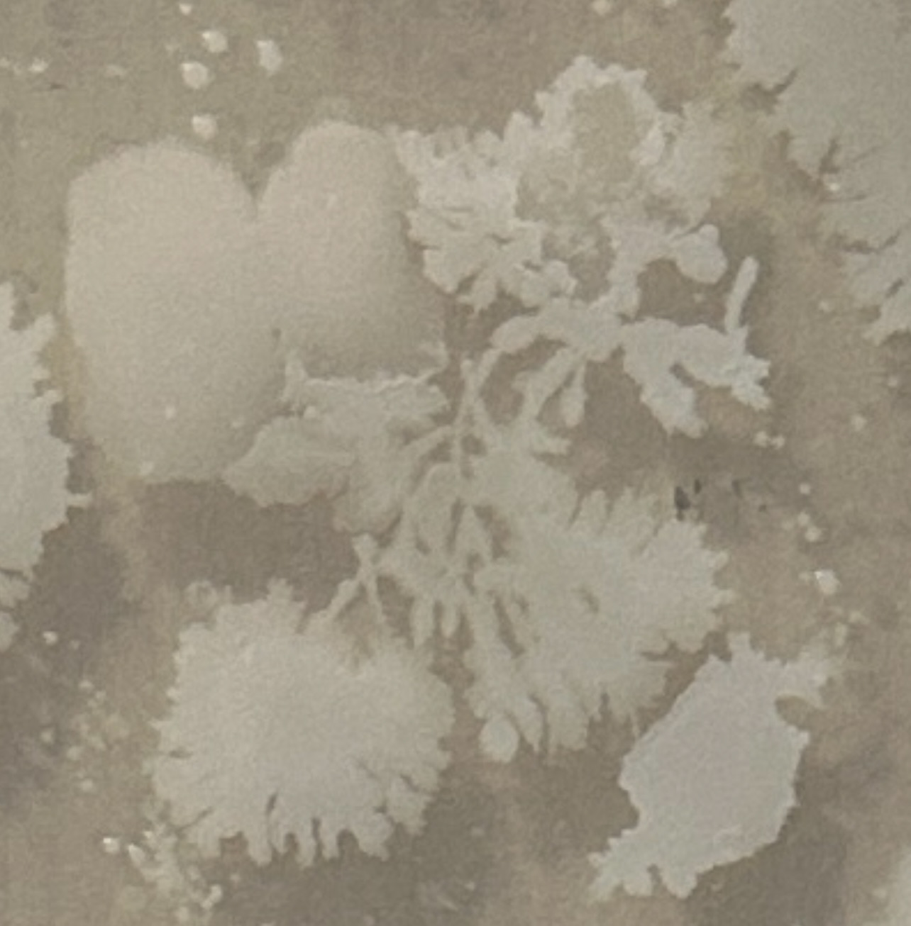
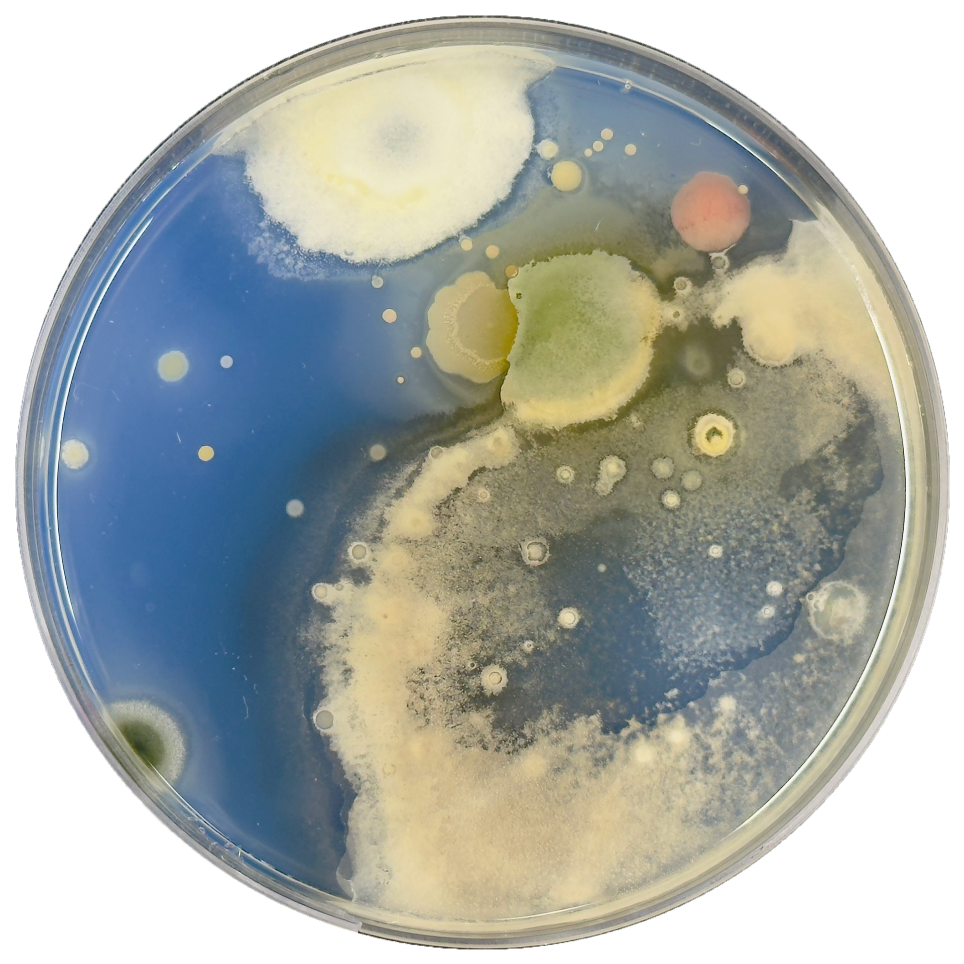
Between days 3 and 7, the bacteria had the most rapid and active growth. The colonies that developed were primarily in shades of yellow and orange, which I have seen in previous experiments. However, something unexpected happened between days 7 and 9. By the 9th day, some of the bright-coloured bacterial colonies had disappeared entirely, replaced by dark brown and black fuzzy growths. This change suggested that another microorganism, most likely a mould or fungus, had taken over. I found this sudden shift incredibly intriguing. In just a matter of days, the growth on the plate had dramatically changed.
This unexpected development has sparked my interest even further, and I’m eager to continue exploring how bacteria and other microorganisms evolve over time. I plan to conduct more trials with additional variables to better understand what influences these changes and whether similar patterns will emerge again.
3D Printing Time Experiments
Building on my previous bacterial experiments, I decided to take one of the samples from day five into Rhino to begin a new model. My goal was to observe how these organic shapes evolved over a nine-day period and translate that growth into a 3D form. By doing this, I aimed to explore how the natural development of bacteria could inform the structure and aesthetics of my designs.
As I worked through this process, I unexpectedly found myself reconsidering my project direction. The experiment led me to refine my overall concept, and as a result, I decided not to continue developing these particular models. However, despite this shift in focus, the CAD modelling was valuable. It allowed me to refine my workflow and become more confident in my approach. I now feel confident enough to begin working on my final models once my last bacterial samples have fully developed.
Below, I show my process of importing the bacterial images into Rhino, using the Sweep2 tool to generate forms, and then refining the model further in Blender. In Blender, I focus on smoothing the structure and making any necessary adjustments to enhance the final design and create the smooth transitions between shapes that I wanted.
Upon reflection, I felt that this specific sample appeared somewhat flat, lacking the level of intricacy I had envisioned. Since the shapes I generate are directly derived from the bacterial growth, I understand that there are limitations in manipulating their complexity as I cant control how they grow. However, this experiment has prompted me to consider swabbing my bacterial cultures multiple times, potentially 3 times per day (all taken at the same time) so that I can select a sample with more intricate bacterial formations. This approach could lead to more detailed and visually engaging shapes when translated into Rhino, potentially enhancing the depth and dynamism of my final brooches.
Showing the process in Rhino
Smoothing the object in blender
Potato Dextrose Agar Results
Pressing my jewellery into the agar
Swabbing my jewellery and transferring to agar
To test the potato dextrose agar (PDA) in comparison to nutrient agar, I conducted an experiment using bacterial samples from my jewellery. I swabbed my ring and applied it to three different agar types: nutrient agar (as a control), standard potato dextrose agar, and a dyed version of PDA that I had made. To ensure a thorough comparison, I created these samples using two different application methods: swabbing the jewellery onto the agar using sterile swabs and directly pressing the jewellery into the surface of the agar.
One interesting part of this experiment was the significant difference in bacterial coverage between the two application methods. Pressing the jewellery directly into the agar resulted in a much denser and more widespread bacterial growth across the plate. This outcome makes sense, as direct contact allows for a greater transfer of microorganisms from the jewellery surface onto the agar. However, despite the larger bacterial spread, I personally found the swabbing method to be more visually compelling. Swabbing produced more intricate, organic patterns, giving the impression that the bacteria were interacting with each other as they spread across the plate.
Another advantage of the swabbing method is the level of control it offers. By swabbing specific areas of my jewellery and applying it to targeted sections of the agar, I could influence where bacterial growth would be more concentrated. This level of precision is particularly useful for my project, as it allows me to direct bacterial development in ways that enhance the visual complexity of the resulting forms. In contrast, pressing the jewellery directly into the agar resulted in a more uniform distribution, which, while effective for coverage, lacked the organic variability that I find most interesting.
I was also pleased to see that adding dye to the PDA did not negatively affect bacterial growth. In fact, the dyed version seemed to have even better results in terms of visible bacterial development, despite all samples originating from the same piece of jewellery. This outcome reassured me that incorporating dye into the agar is a viable approach for enhancing the aesthetic of the agar without compromising bacterial growth. However, upon further reflection, I realised that I had added slightly too much dye to the mixture, resulting in a more intense blue than I had initially intended. Moving forward, in my next series of samples, I plan to adjust the dye concentration to achieve a more subtle, delicate blue hue that complements the organic bacterial patterns without overwhelming them.
This experiment has provided valuable insights into both my material choices and application methods, reinforcing the importance of balancing bacterial growth with artistic control. These findings will inform my next steps as I continue refining my approach and preparing for my final bacterial samples.
Results
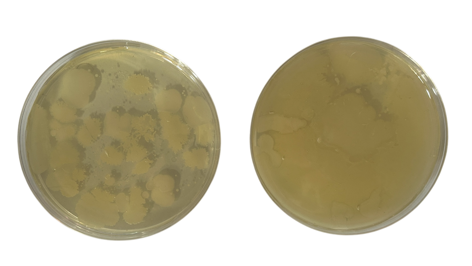
Nutrient Agar
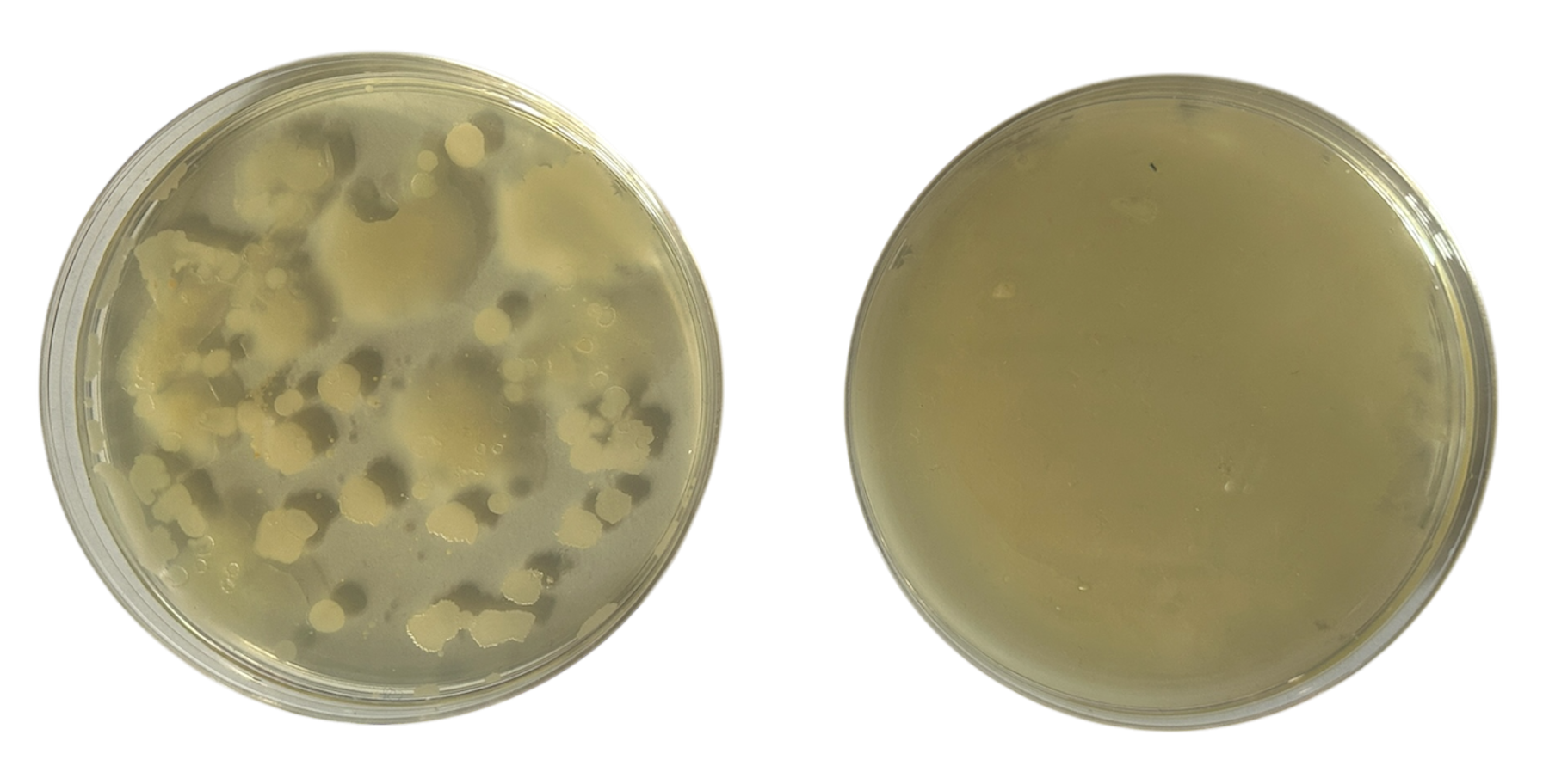
Potato Dextrose Agar
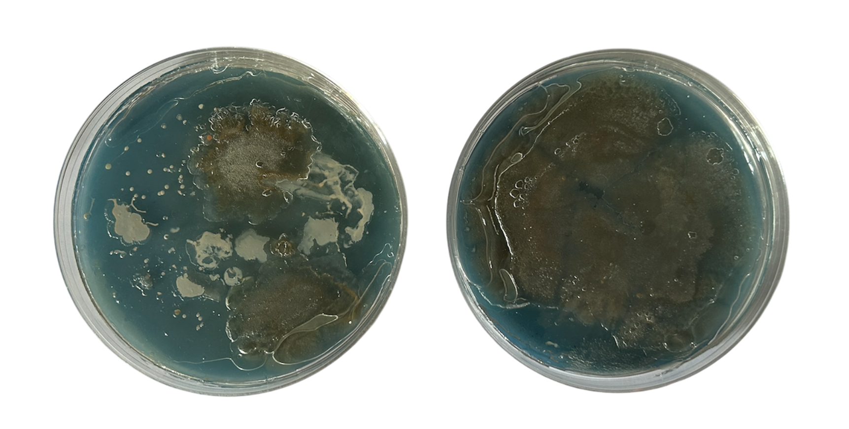
Potato Dextrose Agar
I had three plates left over, and so after the results above, I decided to test only swabbing my ring over 3 days, just to see if there would be any change in the way the bacteria grows.
I found that these samples were much more successful, particularly the middle one.


More 3D Printing
After the previous round of bacteria had grown, I brought the shapes into Rhino to refine my workflow and experiment with scale. Patricia mentioned that she believes my brooches need to be larger, but I naturally gravitate towards working on a smaller scale. I find larger jewellery pieces challenging to work with, and my instinct is always to create smaller pieces of jewellery.
In this case, while I personally preferred the smaller version of my design, I found myself drawn to the larger piece as well. It made me reconsider whether some of these larger forms could stand on their own as brooches - particularly for something like New Designers if I am picked, where I will have additional time after the deadline to continue developing my work.
Overall, I was pleased with the form of this piece and felt that the more intricate bacterial shapes translated particularly well into the 3D agar front. The complexity of these organic forms adds depth and texture, reinforcing the concept of bacterial extension in a visually appealing way.
Printing Space for a Mechanism
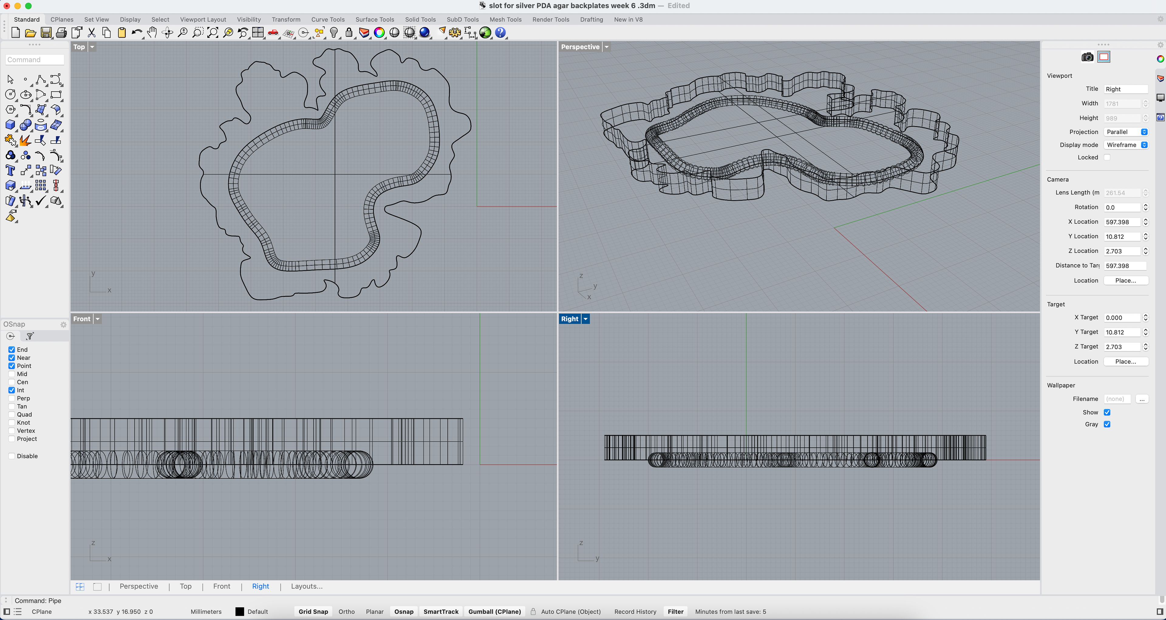
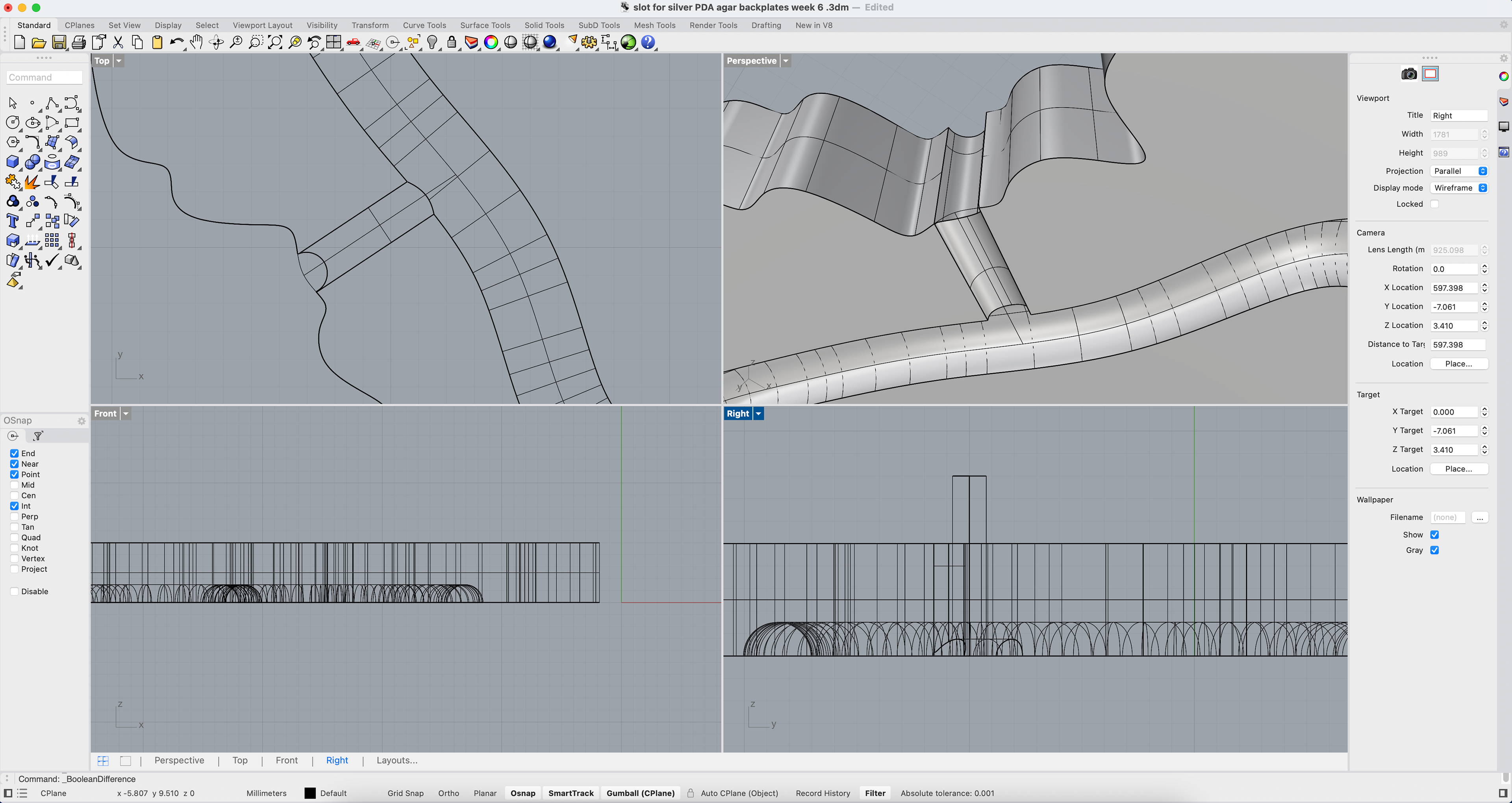
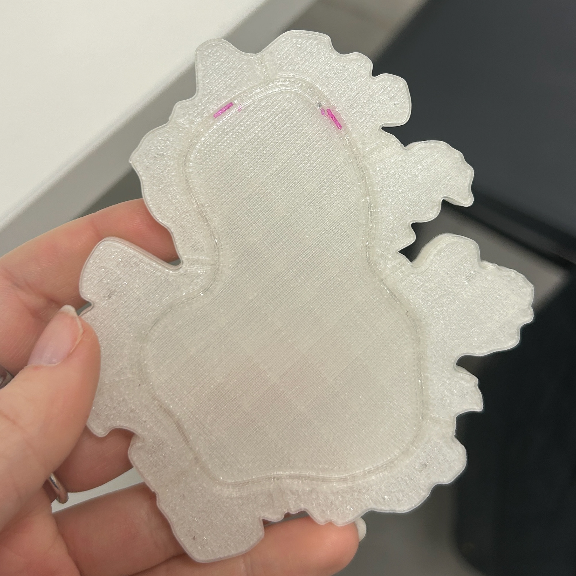
To create the backplate for my brooches, I needed to design a way to make space for the silver wire. The indent had to be circular to match the profile of the wire I planned to use.
I began by tracing the shape of the bacterial growth from the Potato Dextrose Agar in Rhino, following my usual design process. Next, I created a second, slightly smaller shape within the original outline to define the area for the indent, making sure not to make the shape too complex as I would have to bend the wire to fit the shape perfectly. Using the Pipe tool, I generated a line with the same diameter as the wire, starting with 3mm as my initial test. Finally, I used the Boolean Difference tool to subtract this section from the backplate, ensuring a precise and seamless fit for the wire.
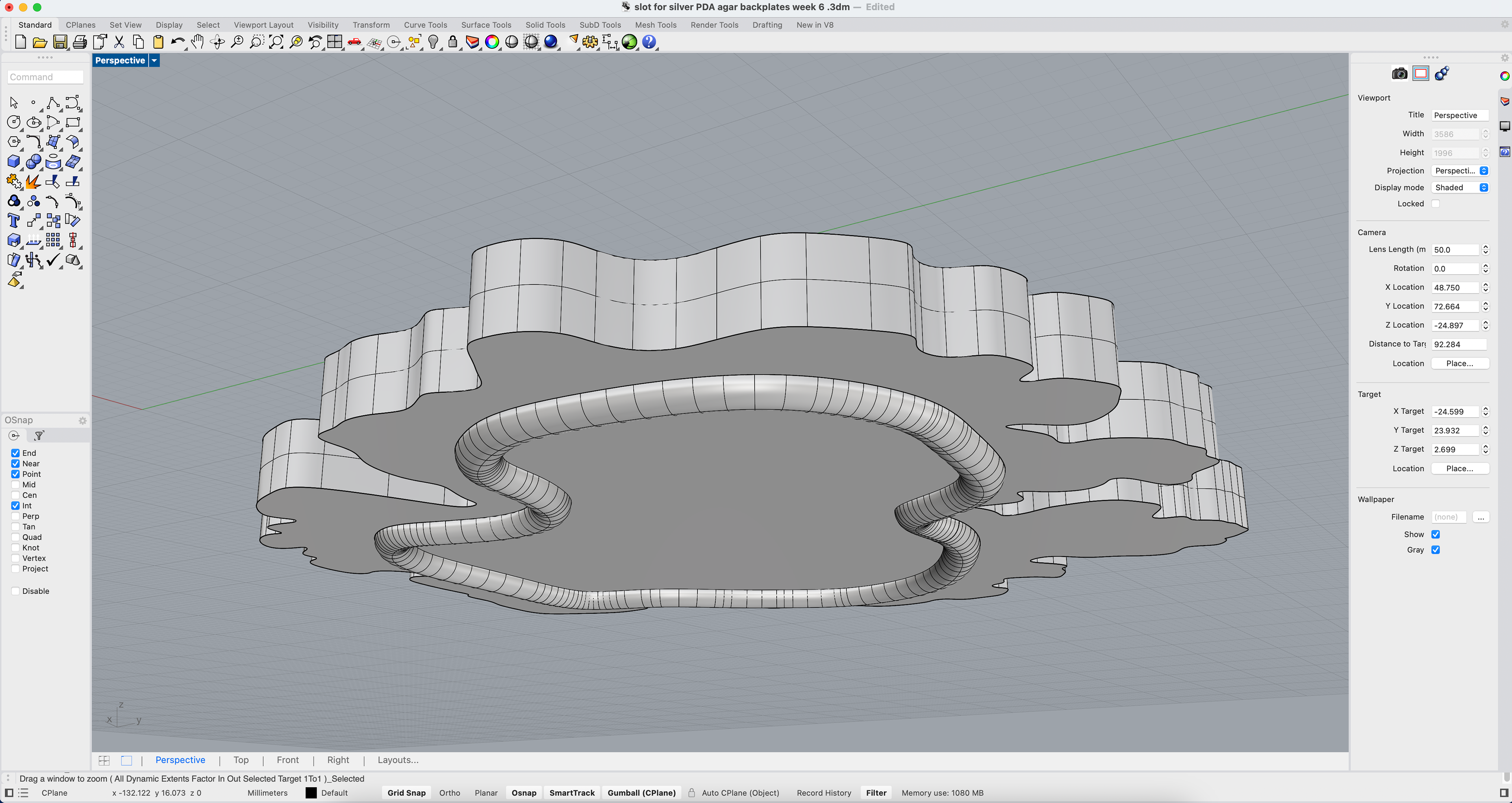
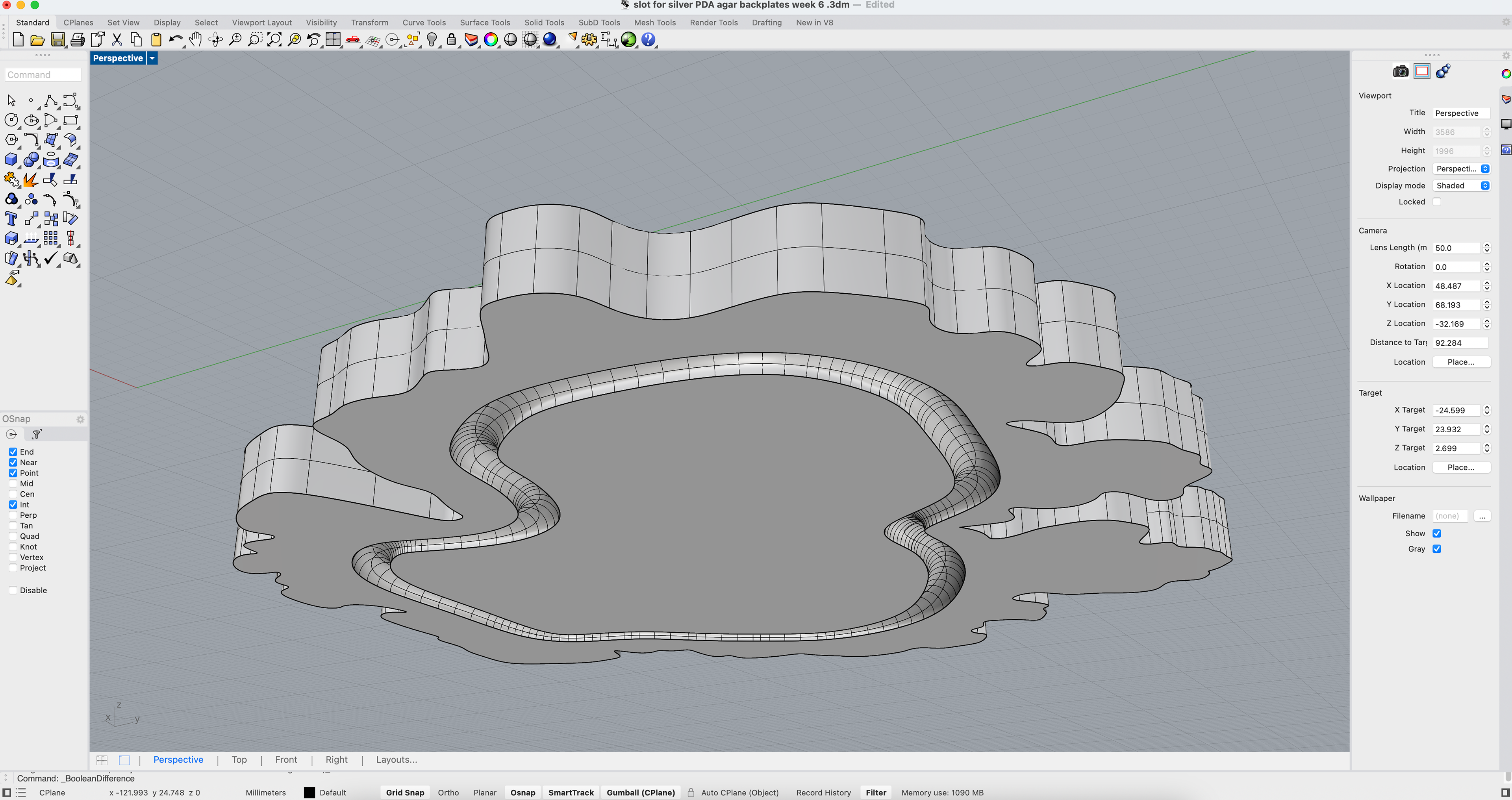
I repeated the same process to create the prongs that secure the outer edge of the backplate to the inner bezel, this time making sure they were slightly thinner. I made this adjustment after seeing the prongs on pieces at Collect, where they were all quite delicate and unobtrusive, allowing the overall design to remain the focal point.
While I think the 3mm indent is too heavy for this design, I am glad that I have worked out how to make this space.
Resin Experiments
At this stage in the project, I was quite worried as I had not been making anything in the metal workshop. I knew that I needed to go in and test this mechanism to see if it would work. I decided to make silicone moulds using my previous 3D prints to then make resin models which I could take into the metal workshop.
I used the same methods as before, as well as the same silicone, as this hasn't caused me any issues.
I then used epoxy resin in the moulds so that I would have resin models to take into the metal workshop, as well as being able to see any adjustments that need to be made.
I found that the backplate needed to be slightly thicker to accommodate the thickness of the agar as well as the change in the thickness of the wire.
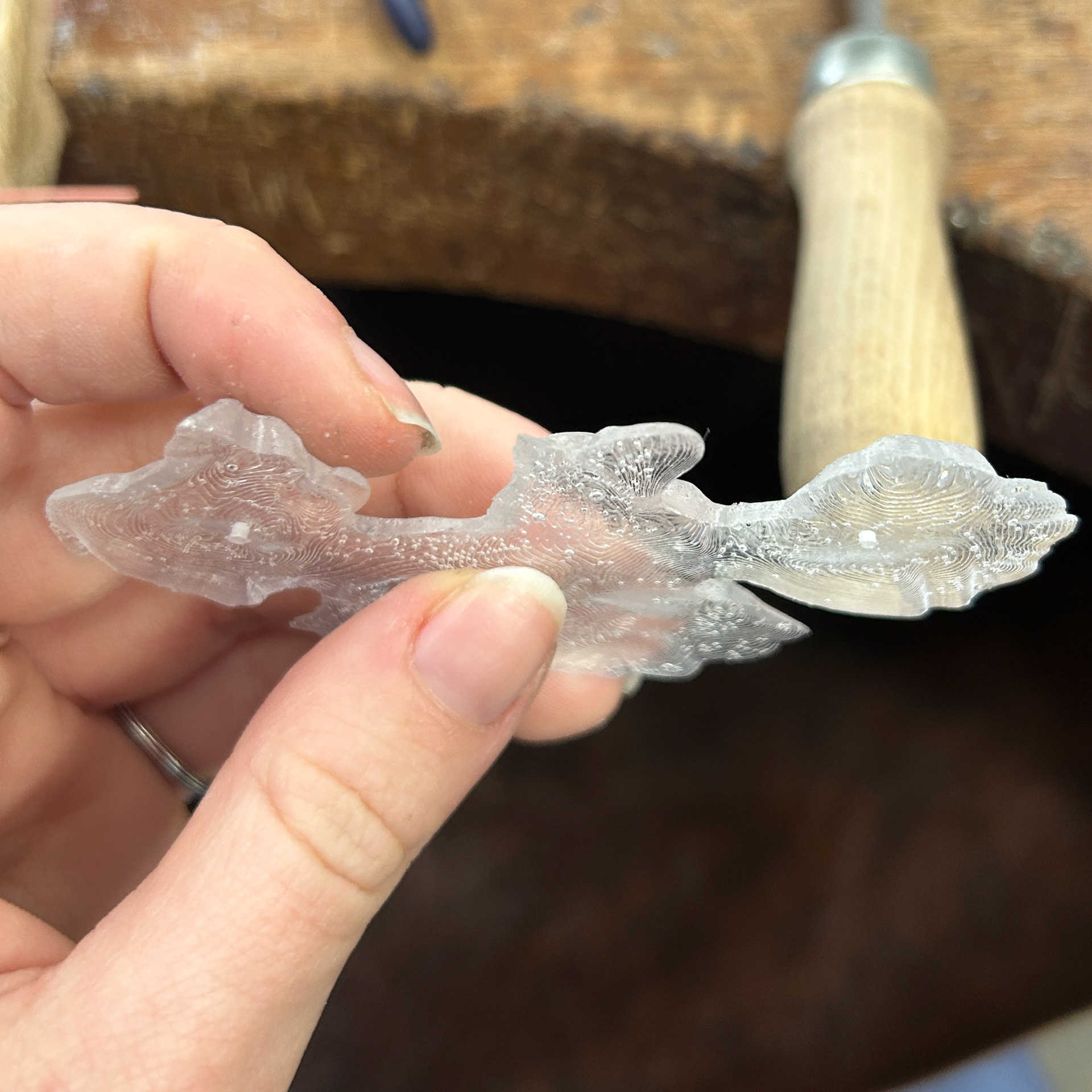
However, this was the first time I was able to envision what my pieces were going to look like. While there was no bacteria, I was happy with the shapes I had made, which was reassuring.
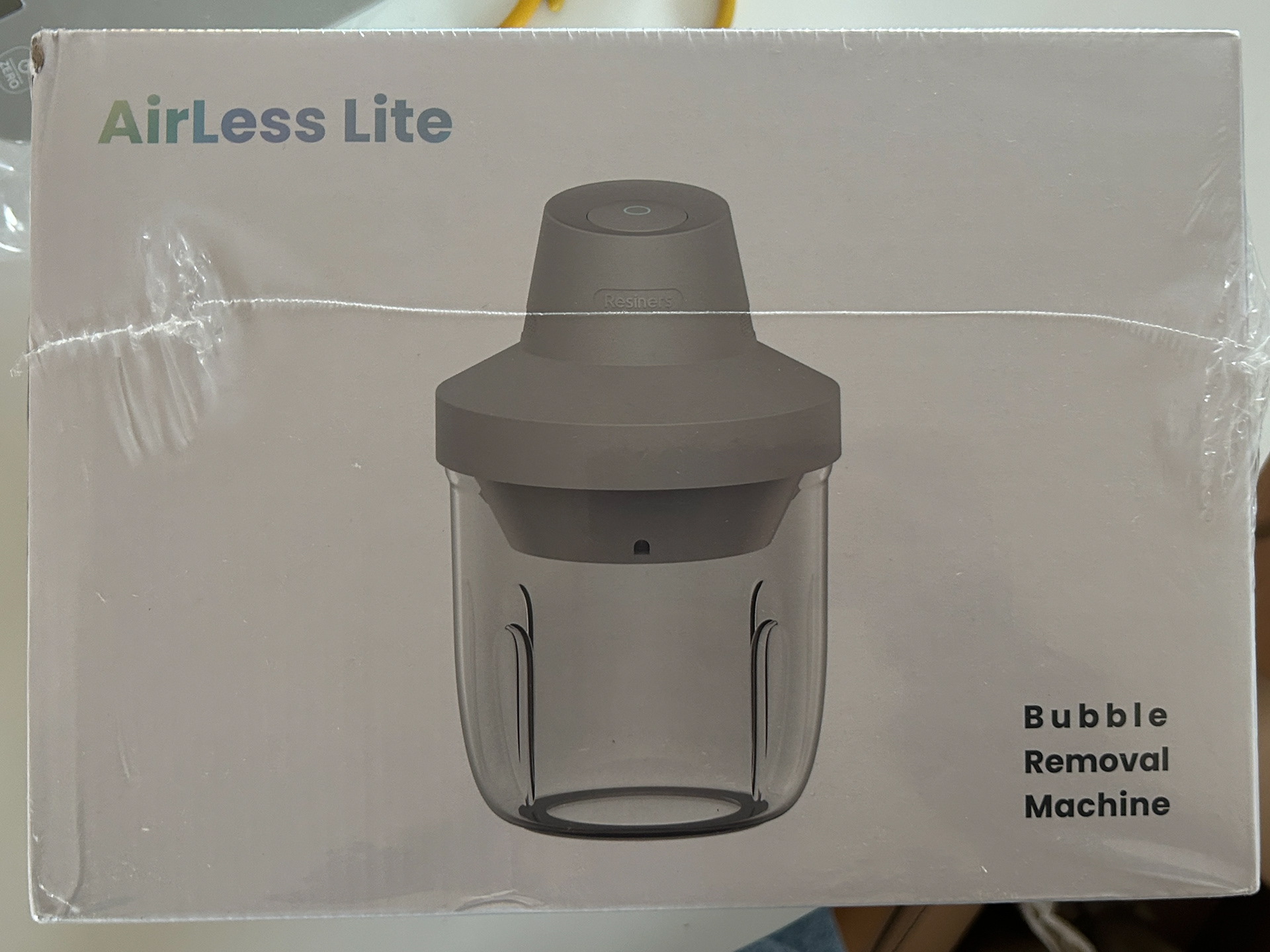
I also have decided to invest in a resin vacuum, as there were far too many bubbles in these pieces, even after using heat to remove as many as possible.
Testing Mechanism
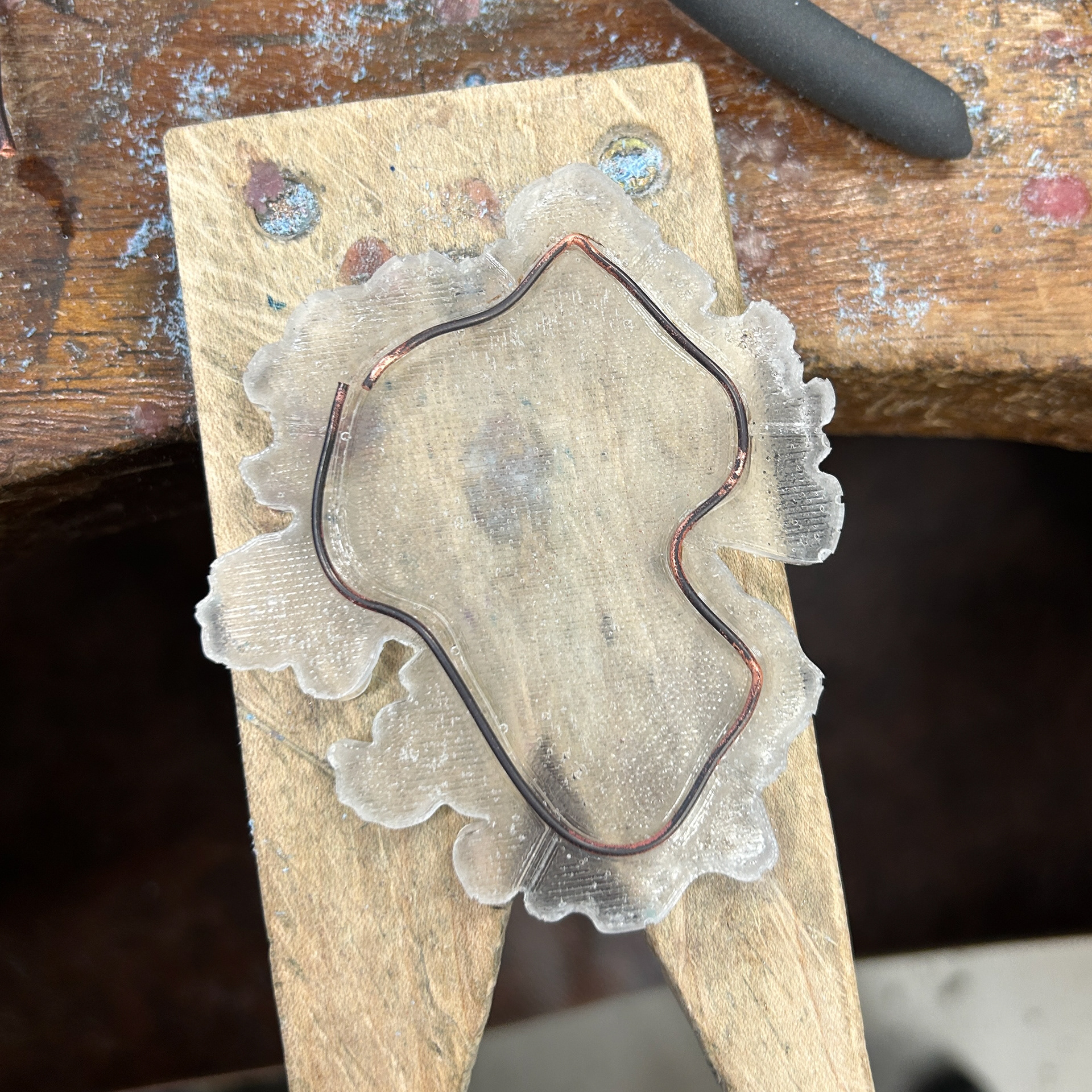
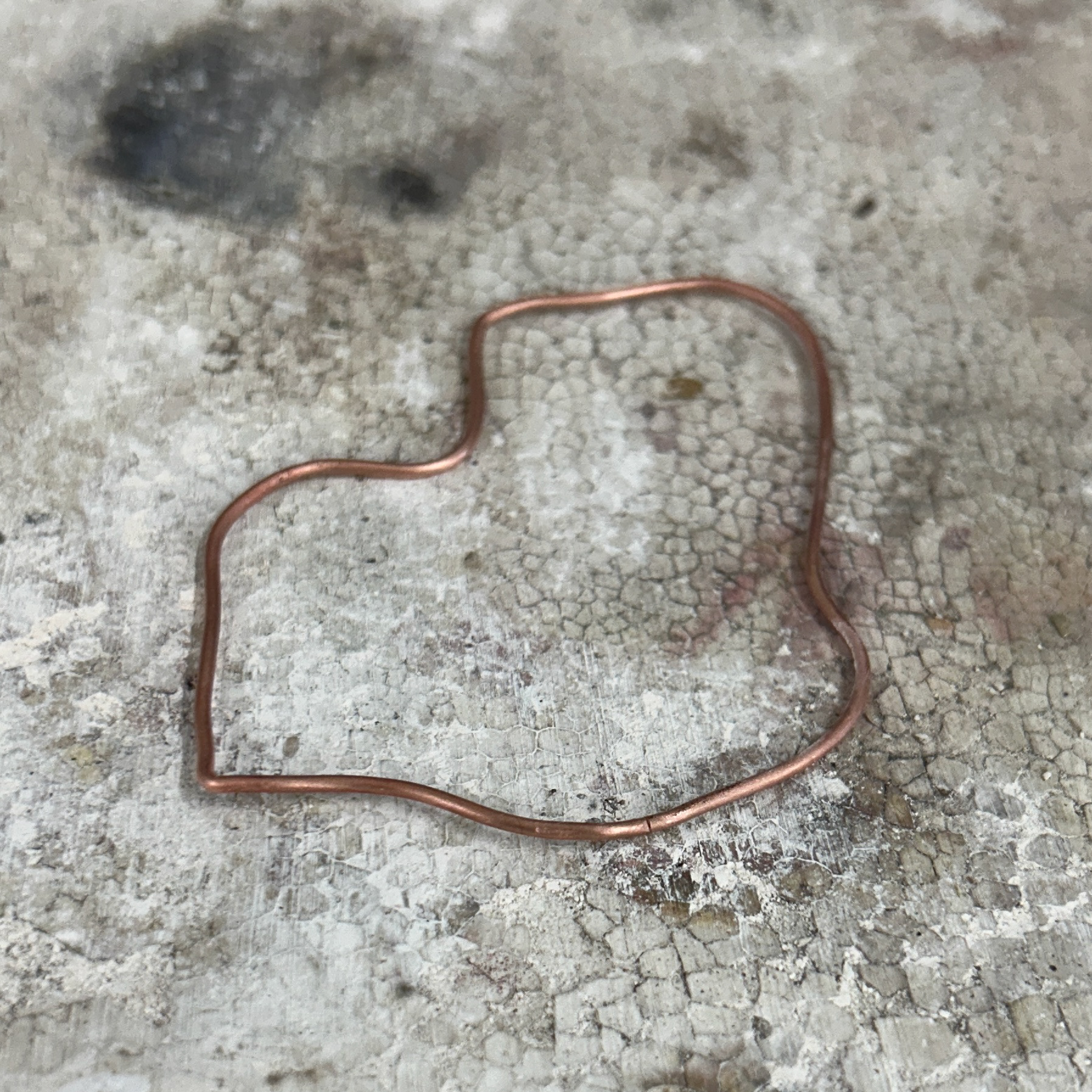
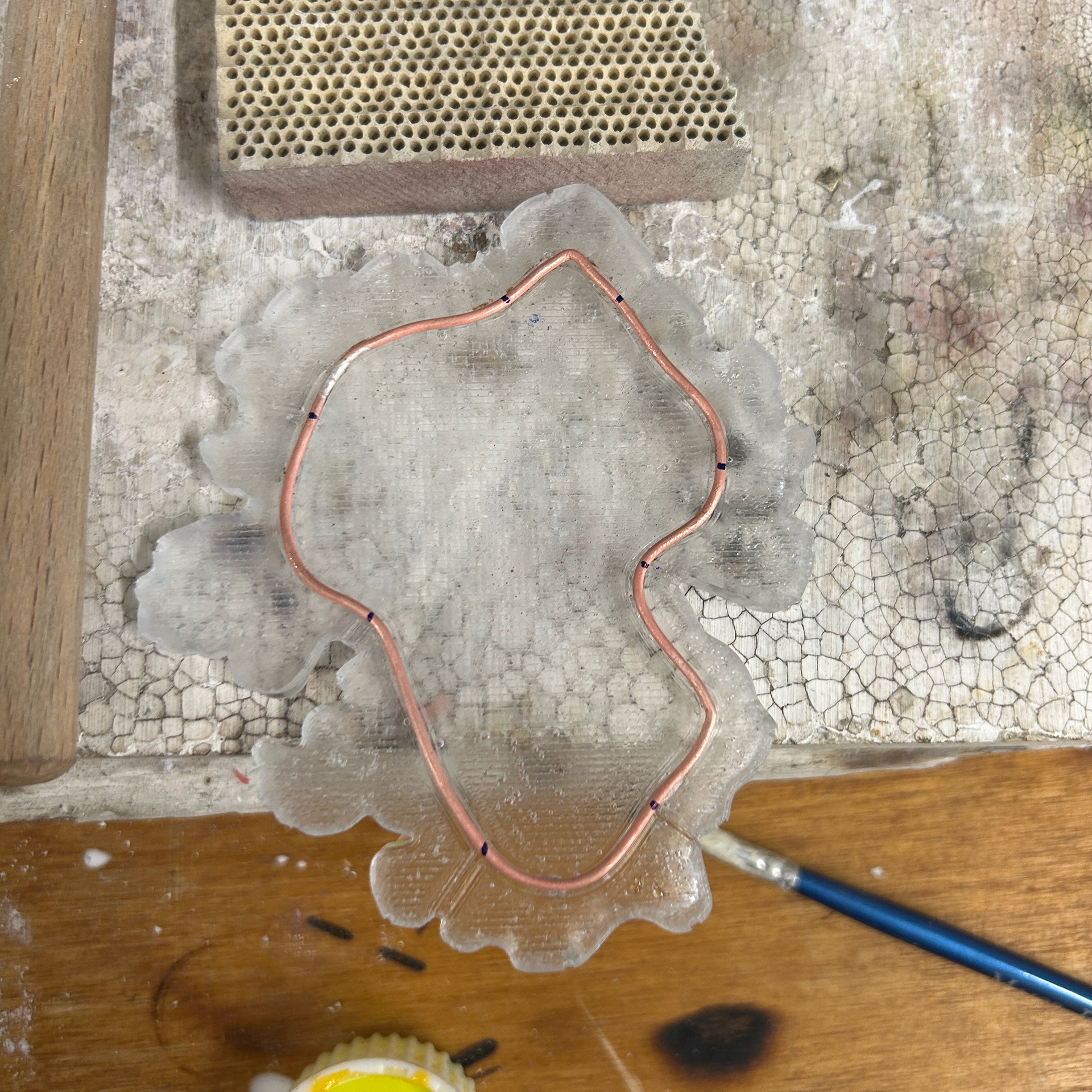
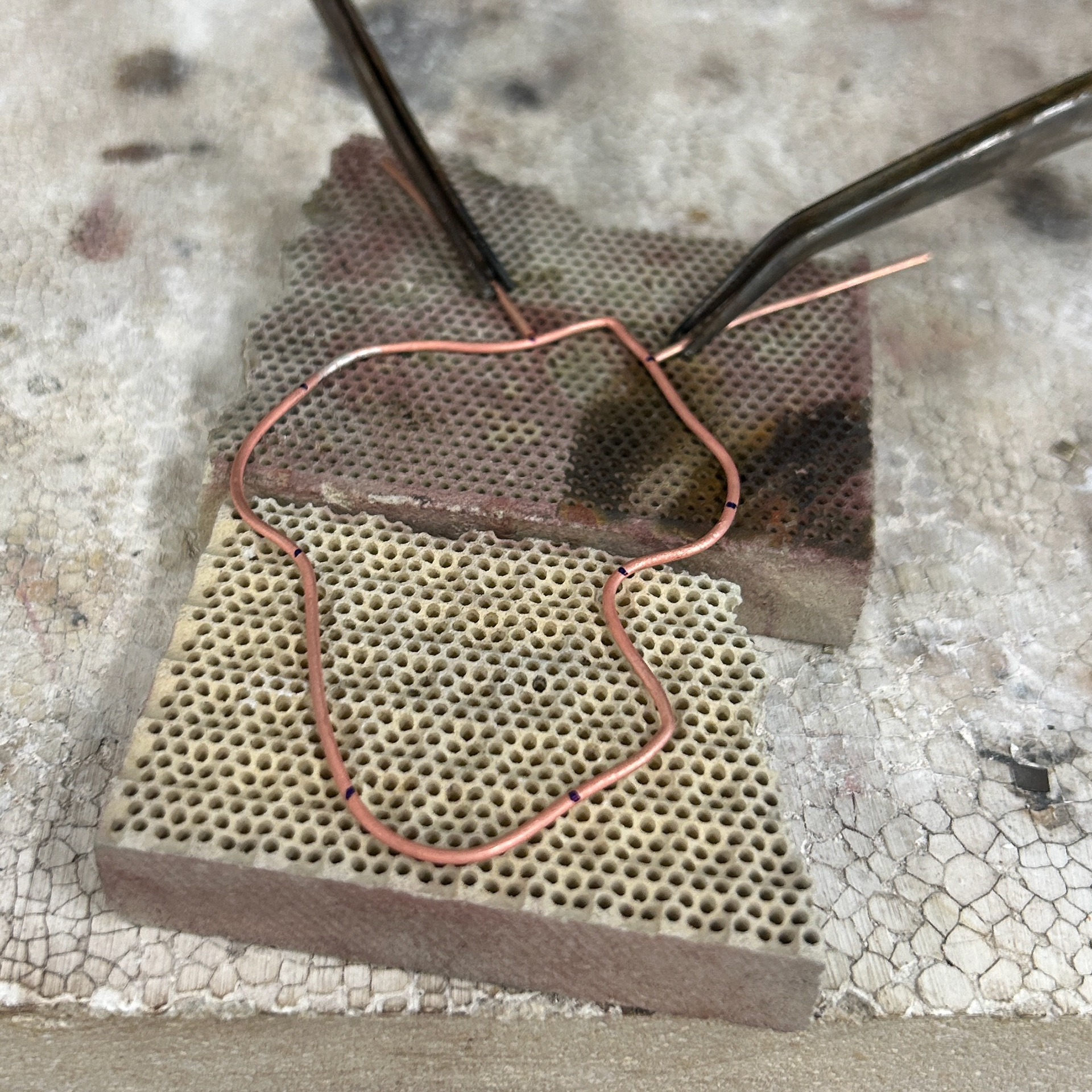
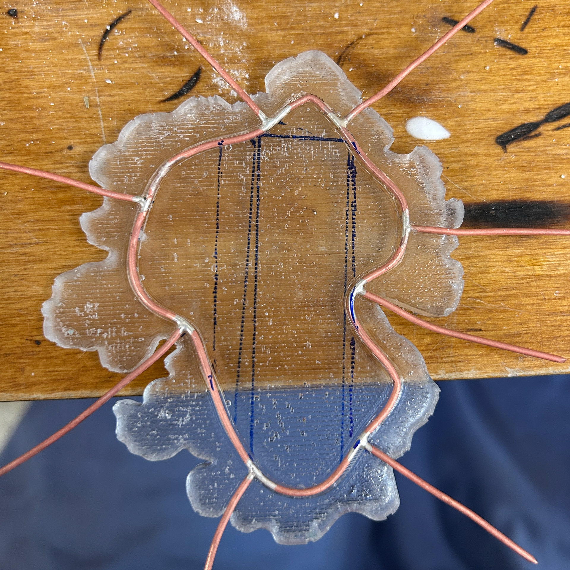
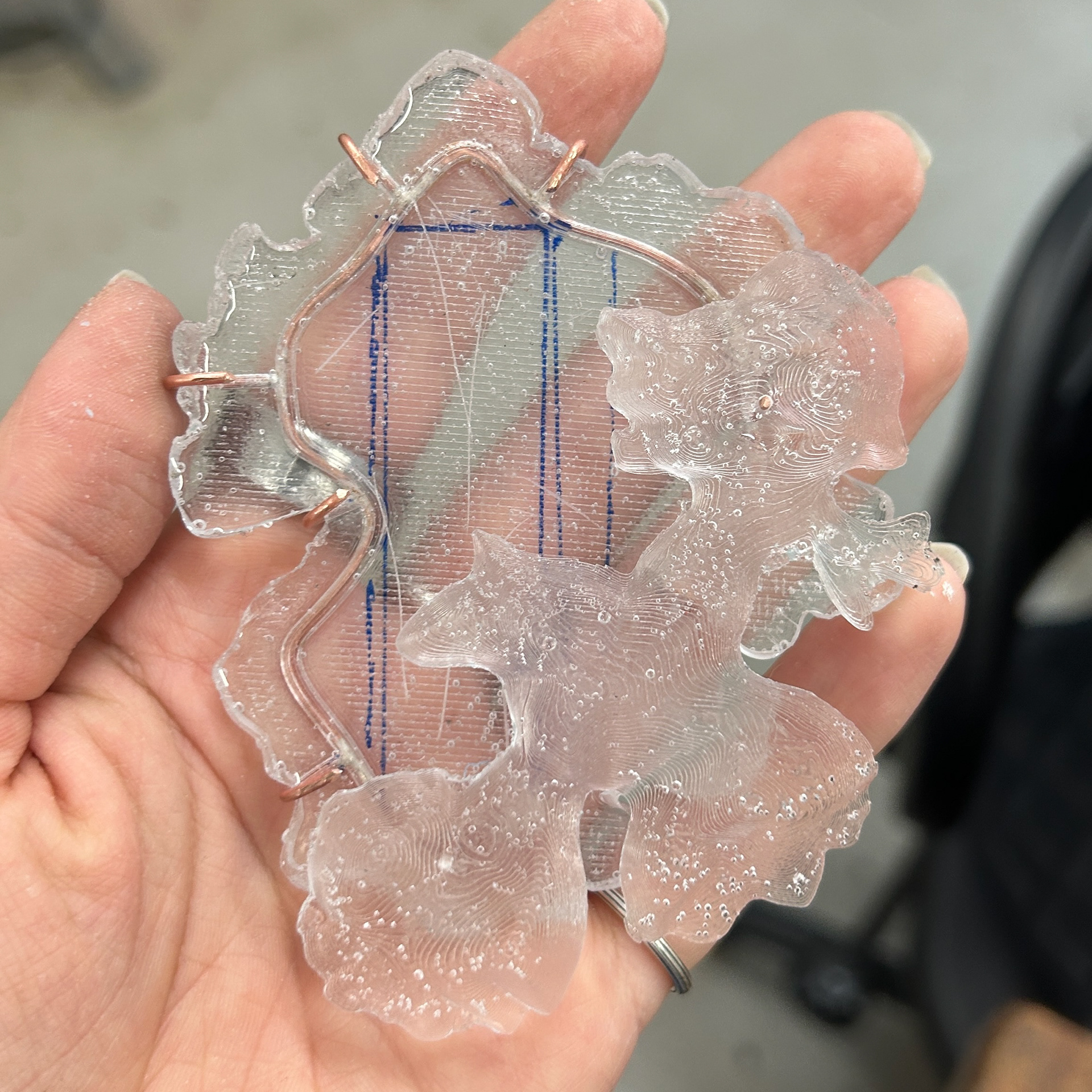
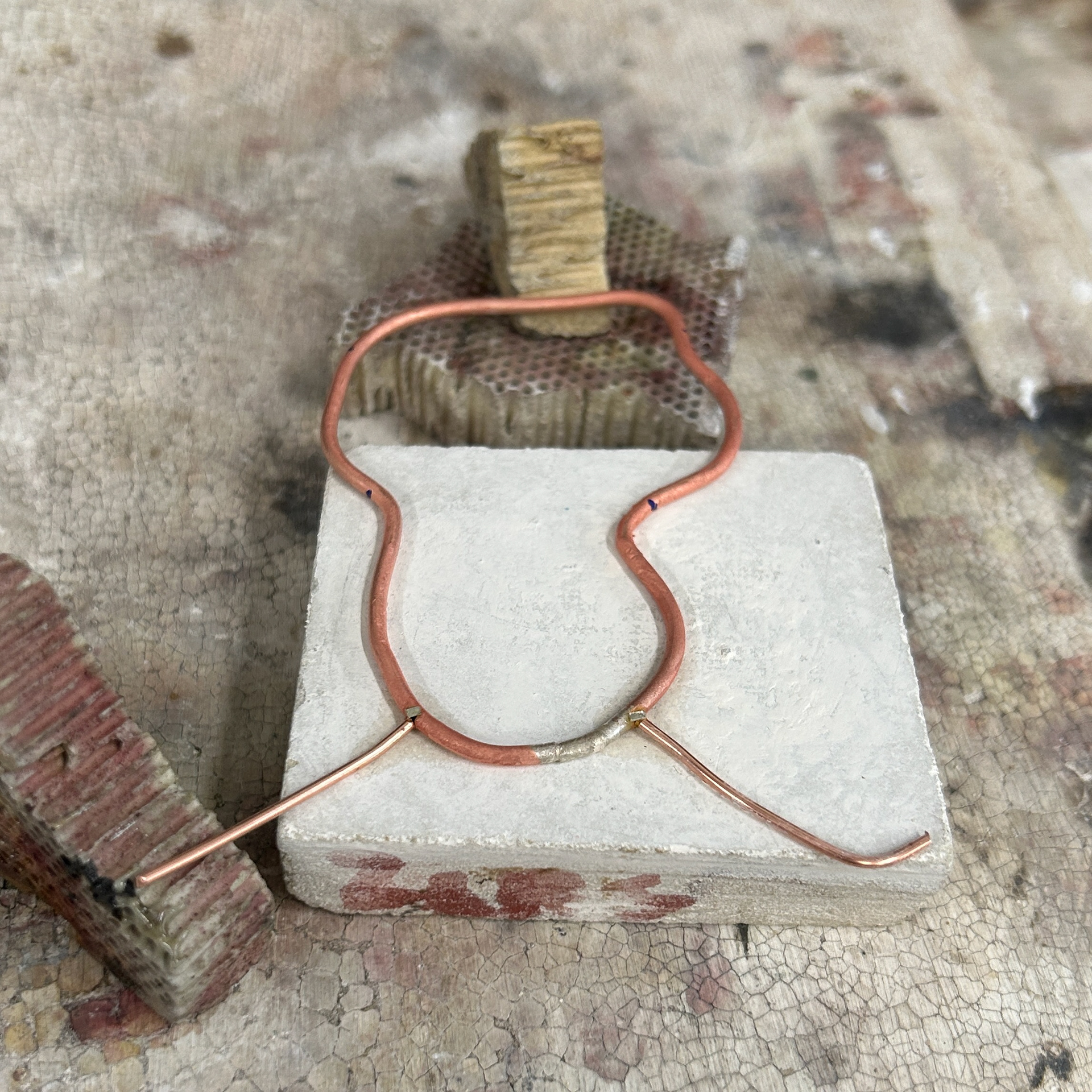
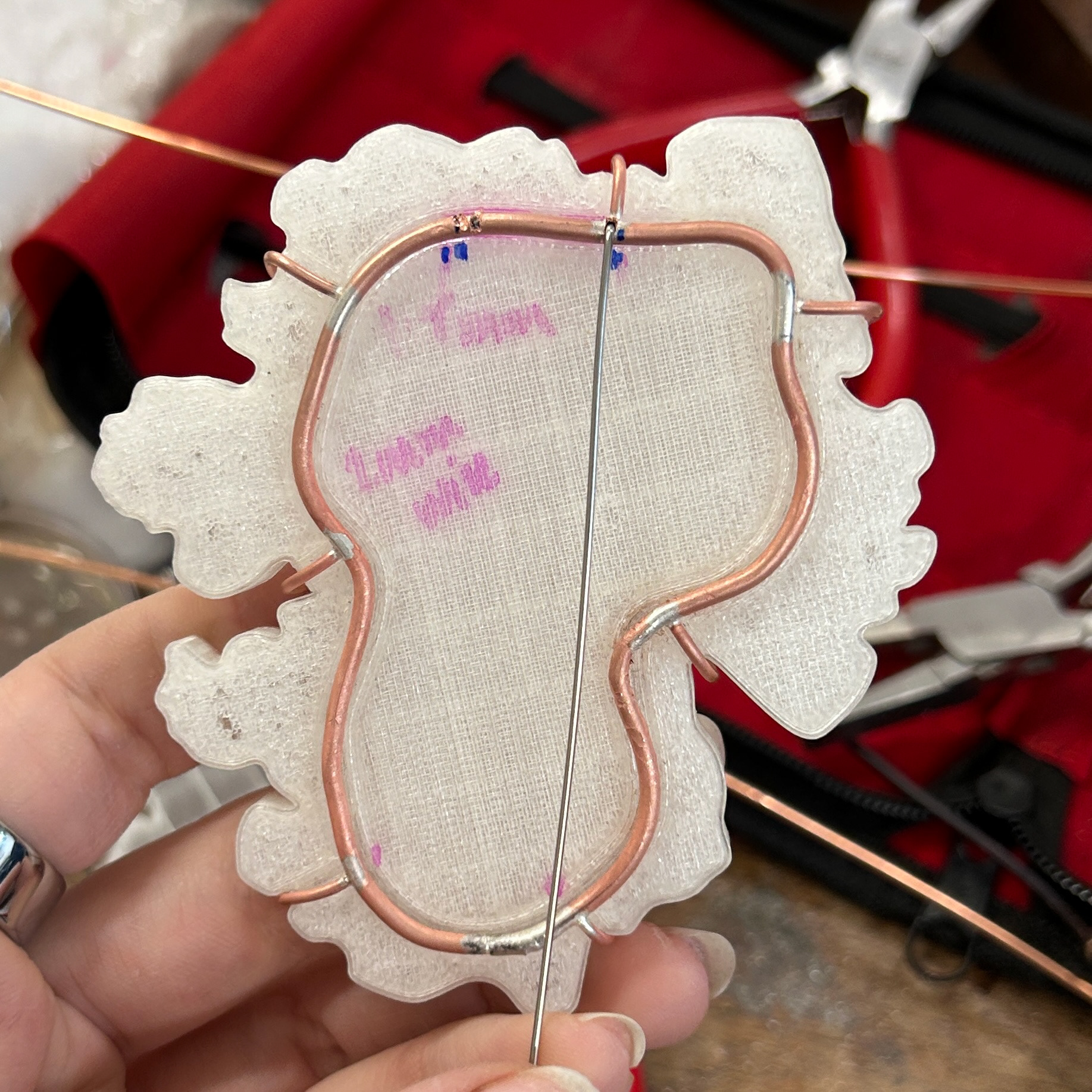
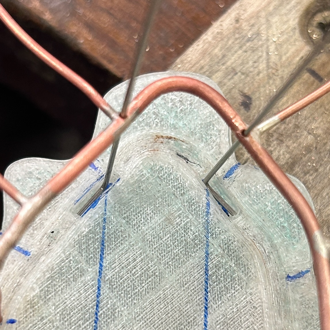
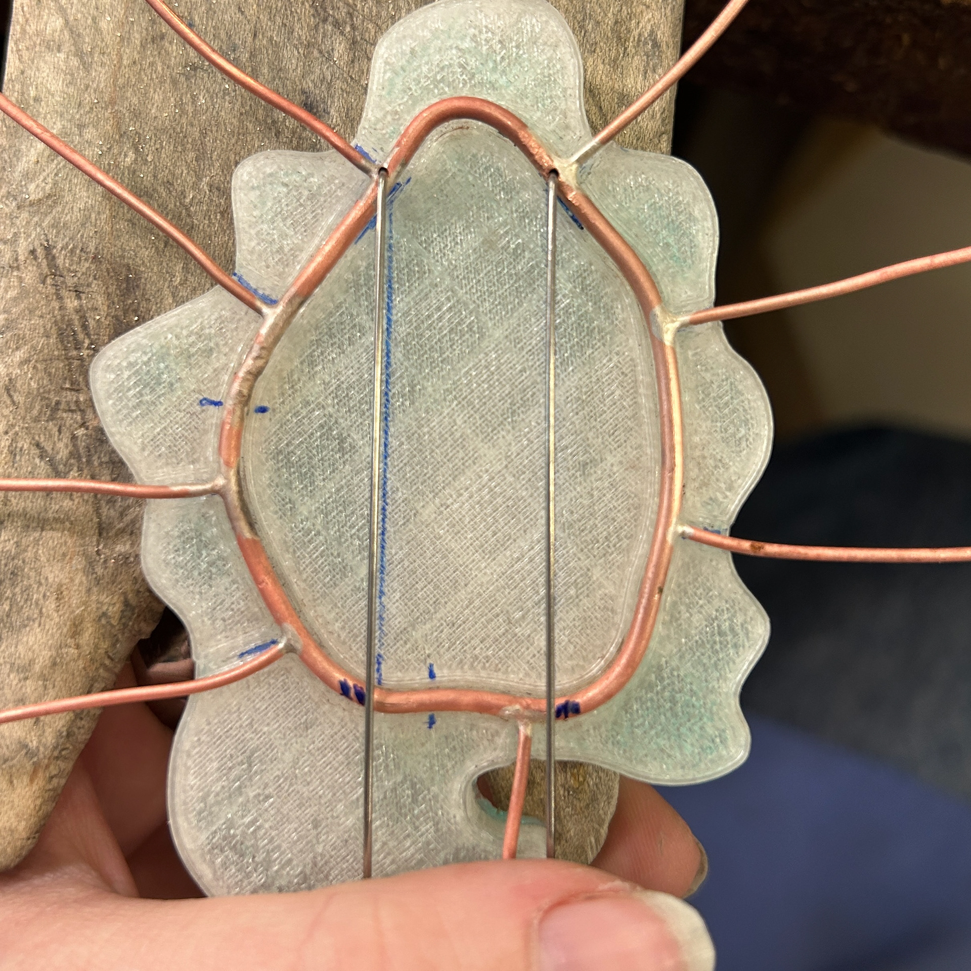
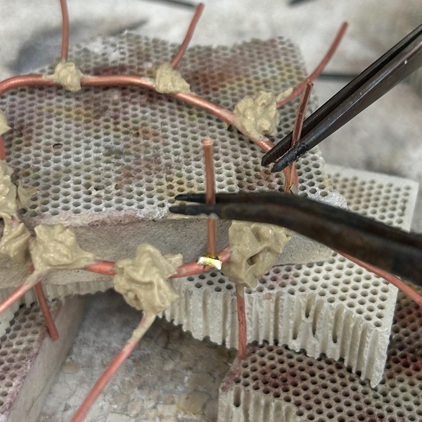
To test the brooch mechanism, I decided to use copper wire to find out which thicknesses of wire I needed before ordering the silver wire. I first tried using 2mm wire for the main back piece outline, however, I found it too difficult to bend into the right shape. I then switched to 1mm wire, which would match the prongs. I annealed the wire and bent it to fit the shape of the inset bezel. This was then soldered shut using hard solder.
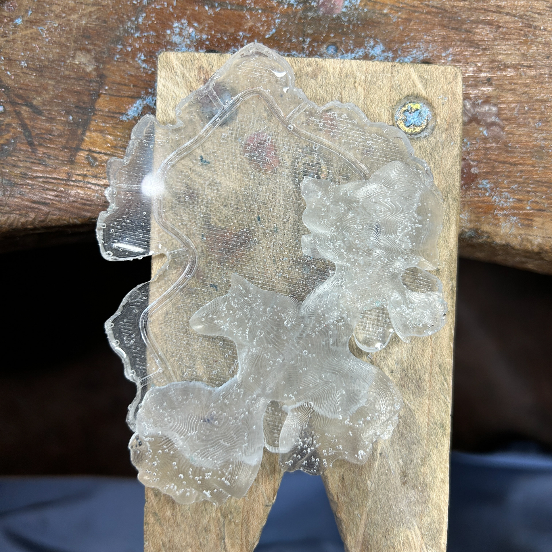
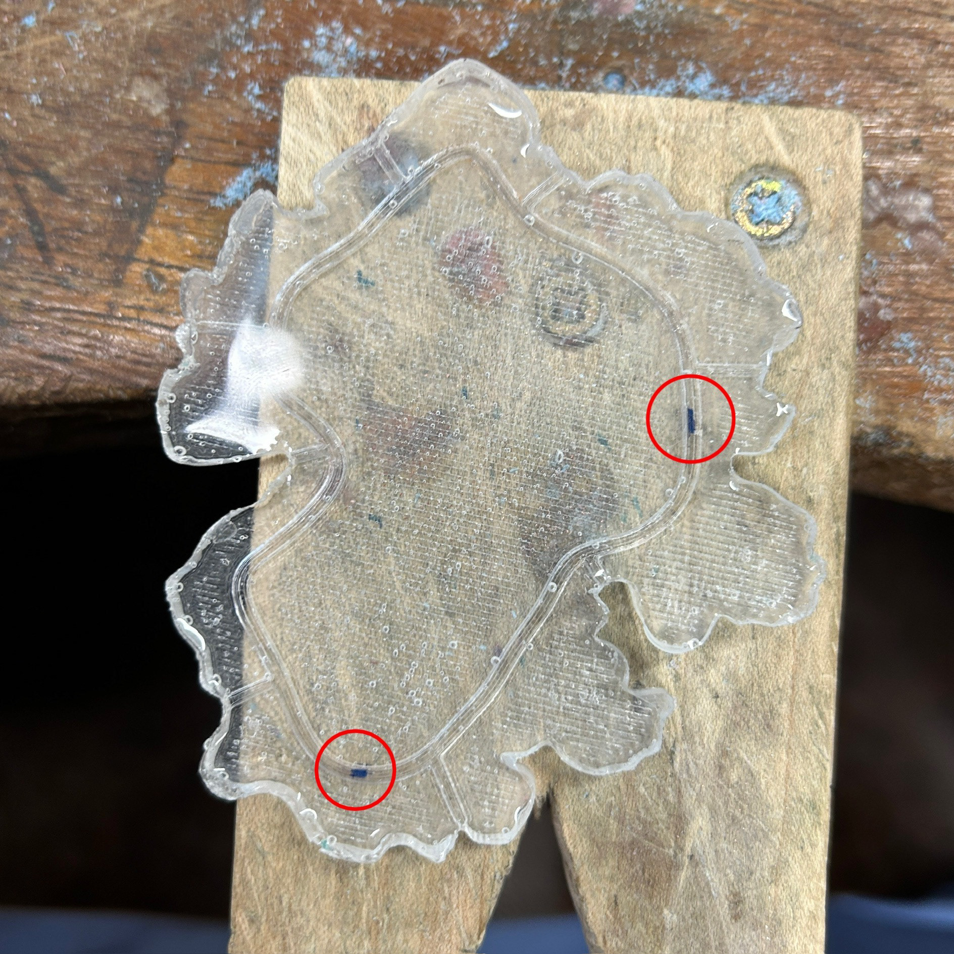
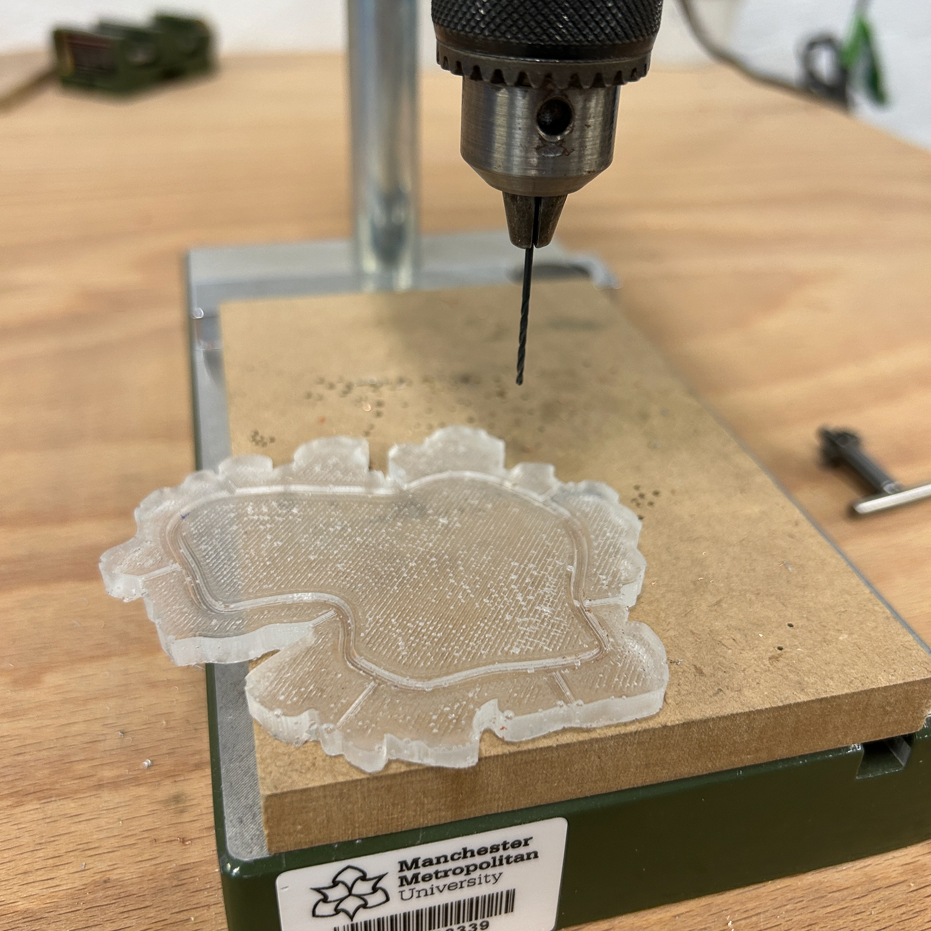
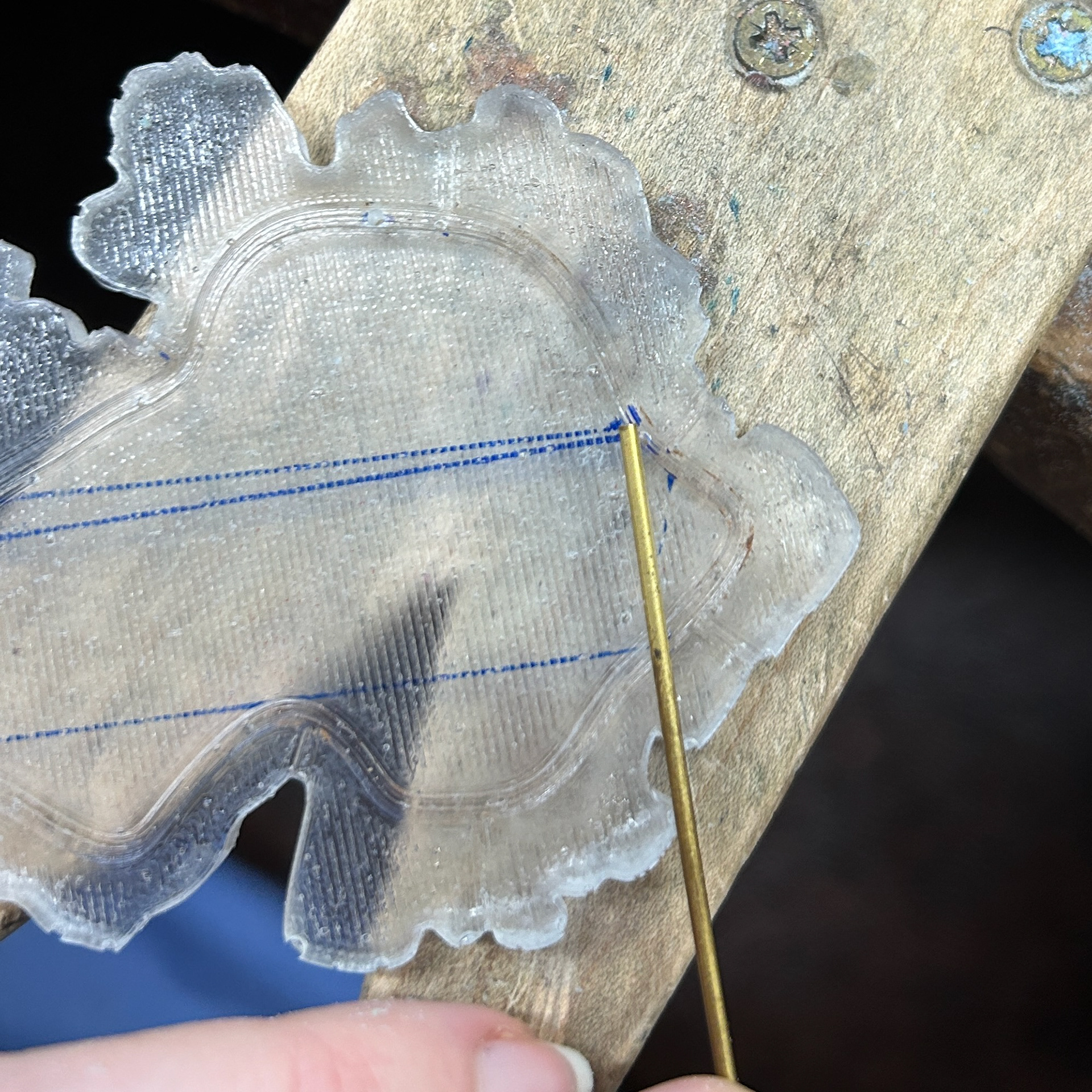
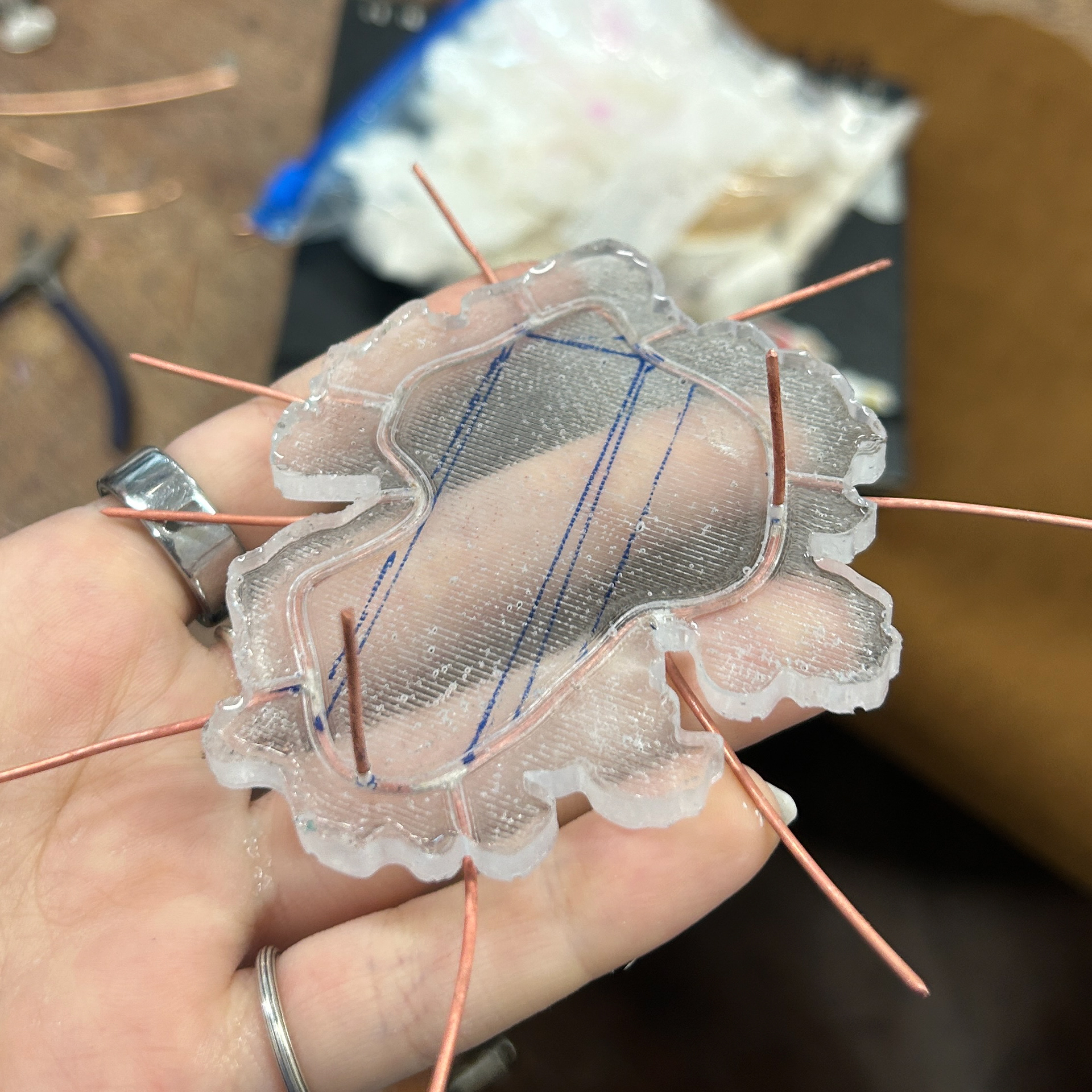
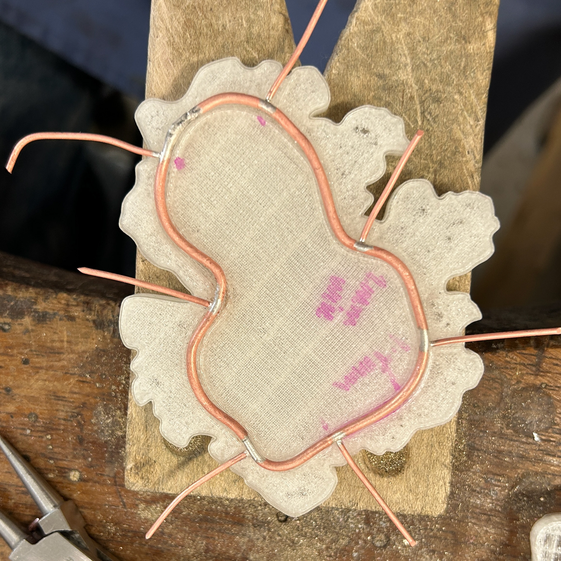
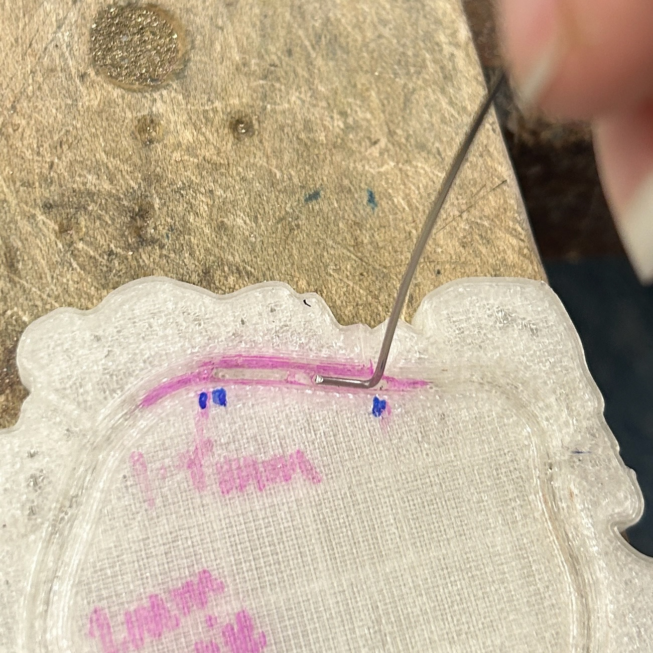
While this piece was pickling, I measured out where the holes in the backplate needed to be, to allow for the wire to pass through from the back. I then drilled these holes using a 1.2mm drill bit.
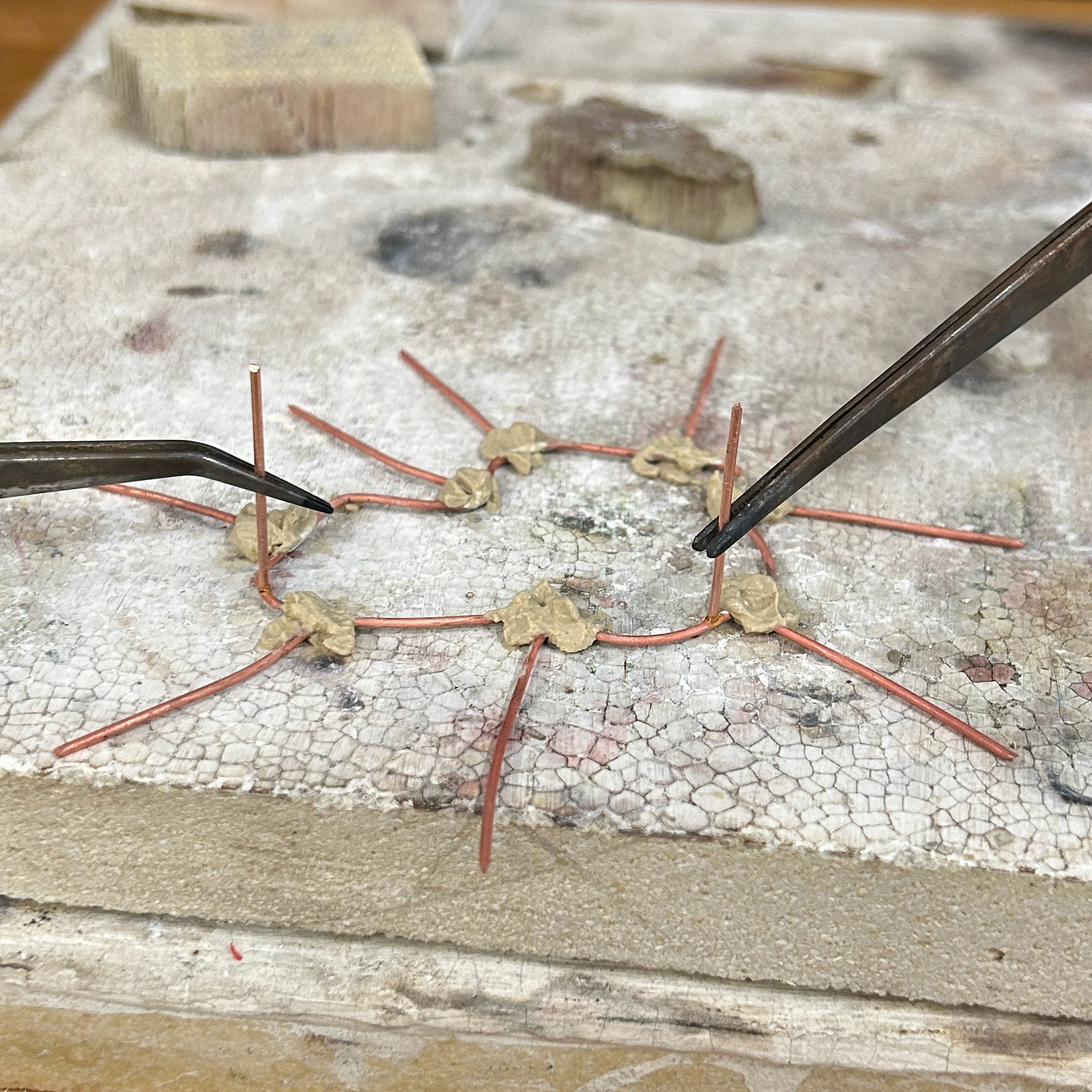
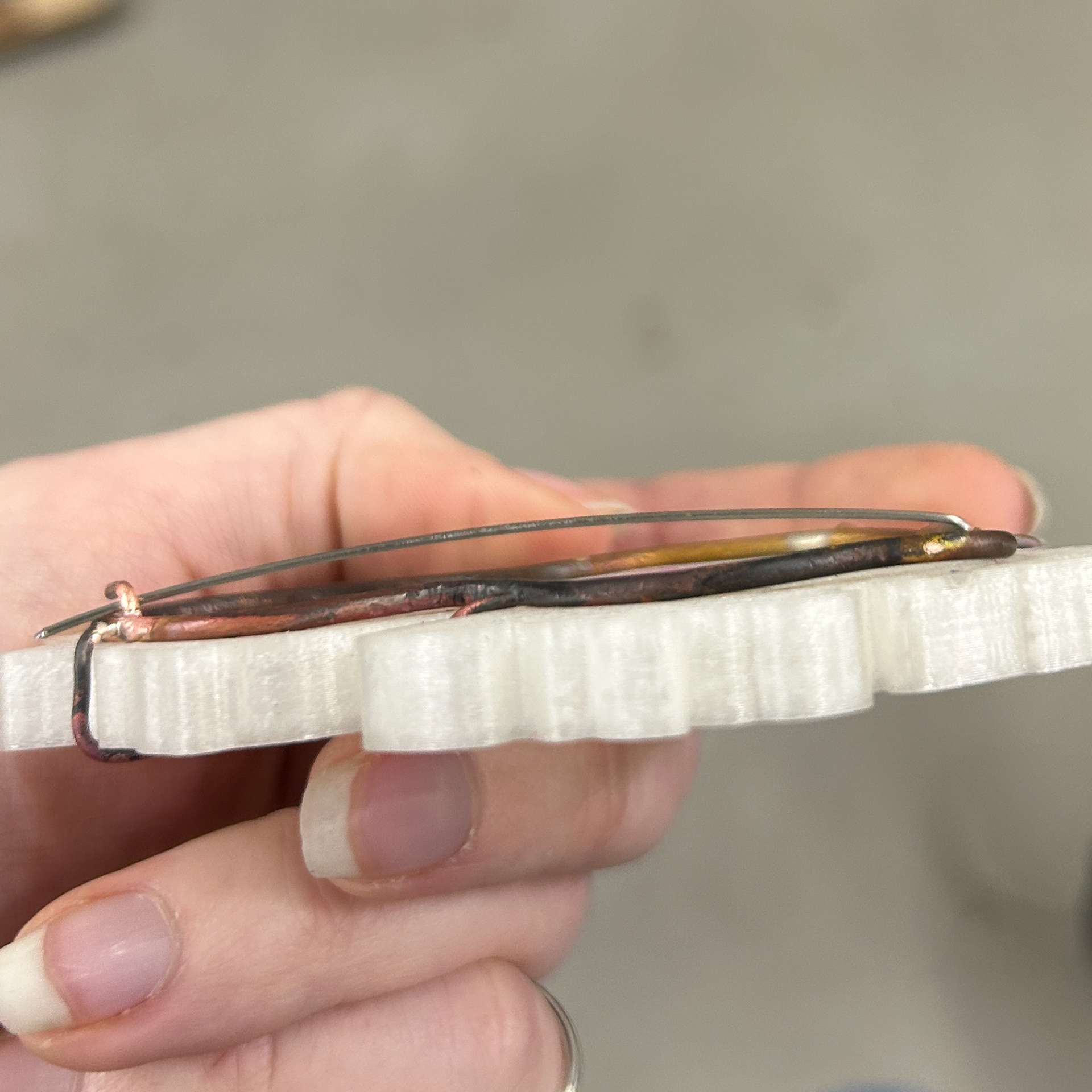
After checking the fit of the wire through the backplate, I then moved on to marking out where the prongs needed to be and then soldering these with medium solder. While there was far too much solder used, which looks very messy and unrefined, I knew that this was just a test piece to get an idea of how the overall brooch would look.
I also measured out where the brass wire would hold the brooch mechanism; however, after seeing how it would look, I felt as if it ruined the aesthetic of the brooch and did not go with the rest of the design. Knowing this, I then started exploring different mechanisms and thought of different ways to have the pins fit seamlessly into the design.
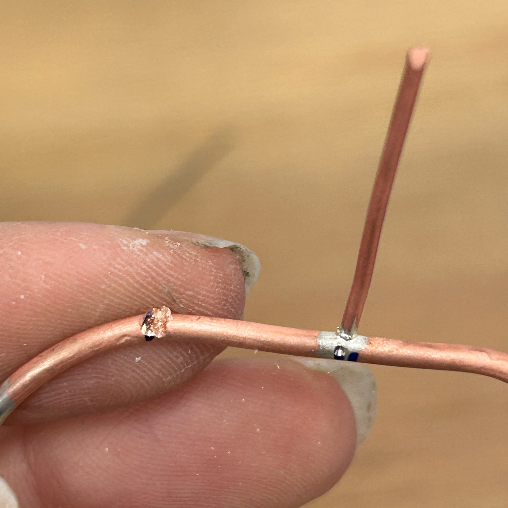
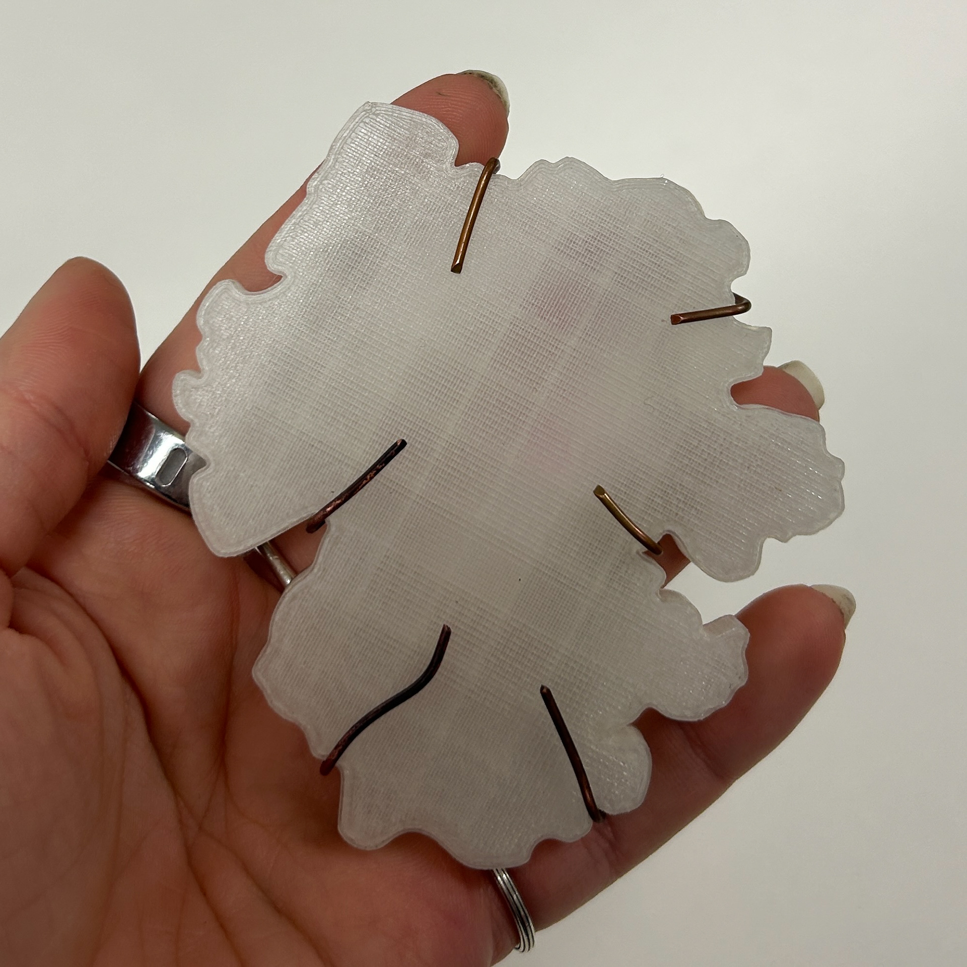
Lastly, I soldered on the prongs that would attach to the front piece, using techniques from Unit X to help prevent any previous solders from running. This was a combination of painting tippex onto the joins, as well as covering them with technoflux paste as a heat barrier.
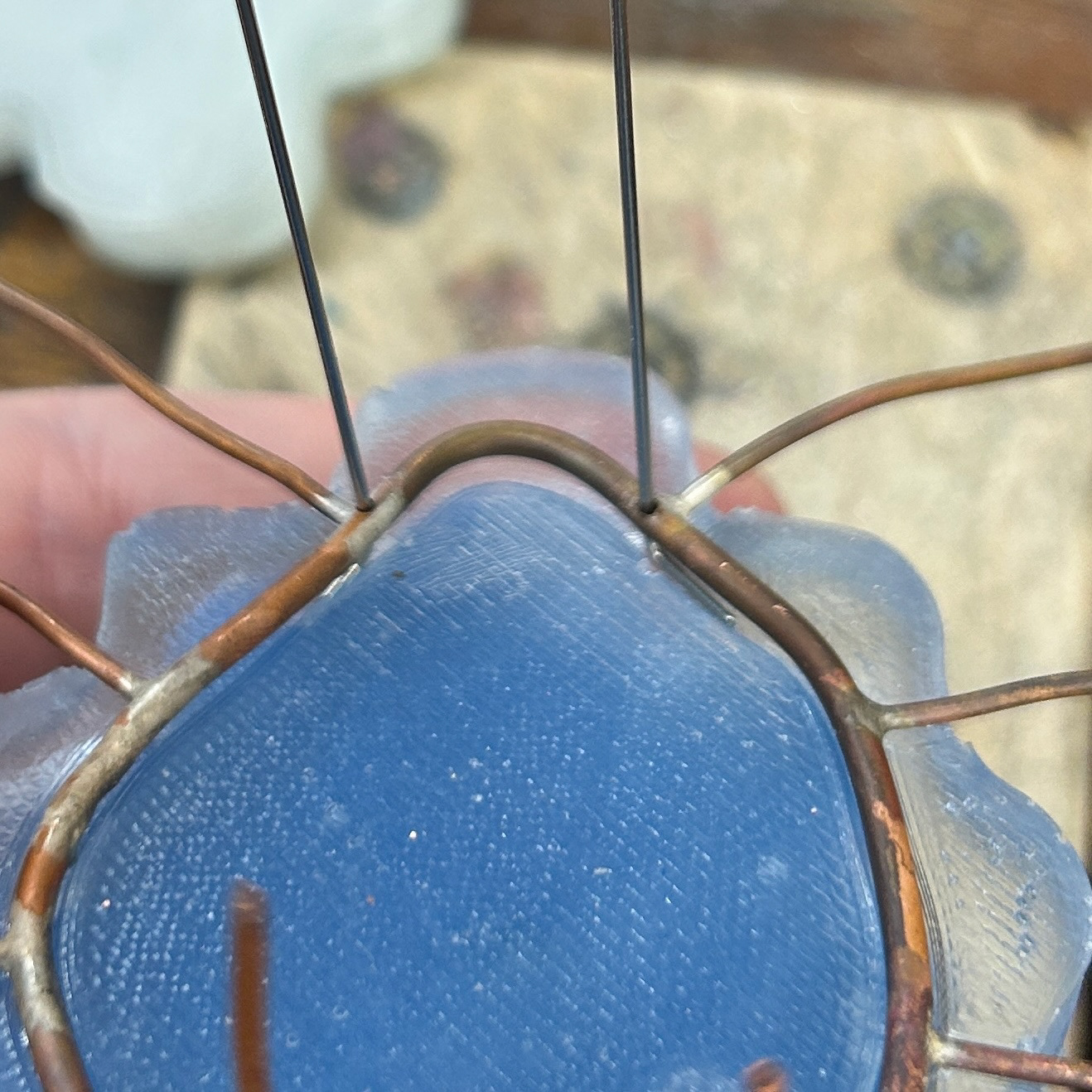
I then drilled into the front piece as equally as possible to make sure the piece would sit as parallel to the back piece as possible and be secured with glue. For my final pieces, I will be using an epoxy glue, which is much stronger and will create a better seal around the wire and the resin.
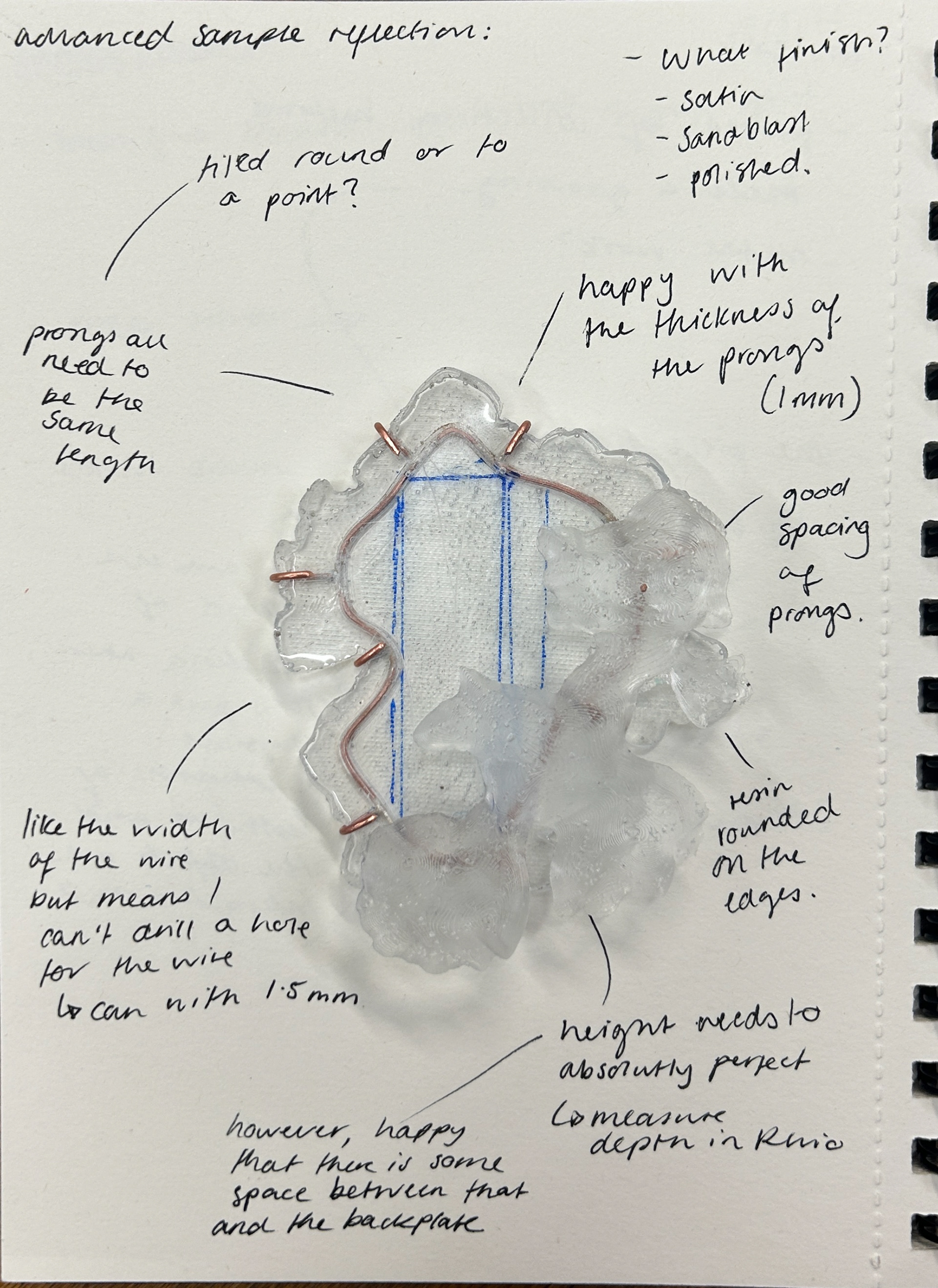
After finishing this sample, I decided to write down all my thoughts about the piece, making note of both the successful aspects and the areas that needed improvement. This process helped me reflect on my design choices and think about how I could refine them further.
One of the things I was most pleased with was the complexity of the shapes. I felt that the two forms worked well together, creating an interesting, visually dynamic design. However, I realise that this might only be the case for this particular combination and that other combinations may not work as well. I will test any combinations in Rhino before committing to printing and making silicone moulds.
The thickness of the prongs was another detail that stood out to me, I liked how they added a sense of delicacy while still being functional.
That being said, I realise there are some areas that needed adjustments. The depth of the 3D print, for example, needed to be thicker to properly accommodate the agar, as this thickness would not account for a layer of agar in the middle. I also think that the edges of the resin could benefit from being rounded. Sharper edges made the piece look slightly unfinished, whereas a smoother, more polished shape would enhance the organic feel I was aiming for. This rounded edge would also help secure the prongs into place, as they would sit flush with the curvature of the resin.
At this stage, I also began thinking more critically about the brooch mechanism and came up with a new idea for how it could function more effectively. I realised that the main bezel needed to be made from a thicker wire to properly support the mechanism. However, using thicker wire meant it would be harder to bend, so I had to reconsider the shape of the bezel itself. To make sure I could still achieve the seamless fit I wanted, I decided to adjust the curvature slightly, making the curves less pronounced, as that would be easier to manipulate while still maintaining the integrity of the design.
Reflecting on these details gave me a clearer direction for the next steps, helping me refine both the structural and aesthetic aspects of the piece before moving forward with the final pieces.
Testing the Brooch Mechanism
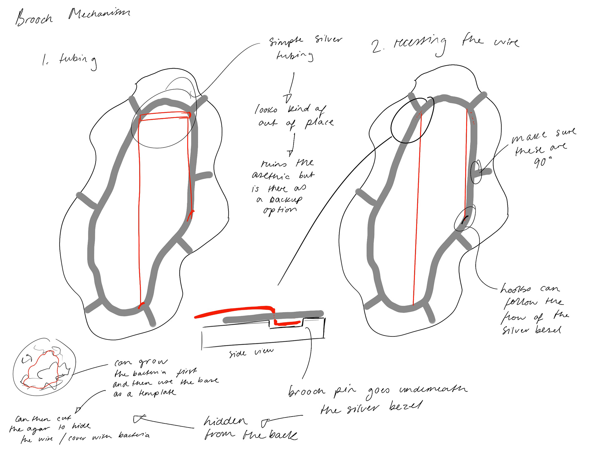
As mentioned above, I knew that I wanted to change the brooch mechanism. I started exploring different ideas and settled on an idea where the brooch pins come through the wire. I would be able to design an inset for the wire in Rhino, and test where the brooch pins could go. This idea would also add tension to the wire, which is essential for brooch pins. This was inspired by a few of the brooches I had seen in 'To The Point'.
I started by modifying my previous print in Rhino, making the space for the wire thicker to allow for 2mm wire, as well as adding two indents for the base of the brooch wire to go.
I then created the same prongs to see how the brooch would look as a whole.
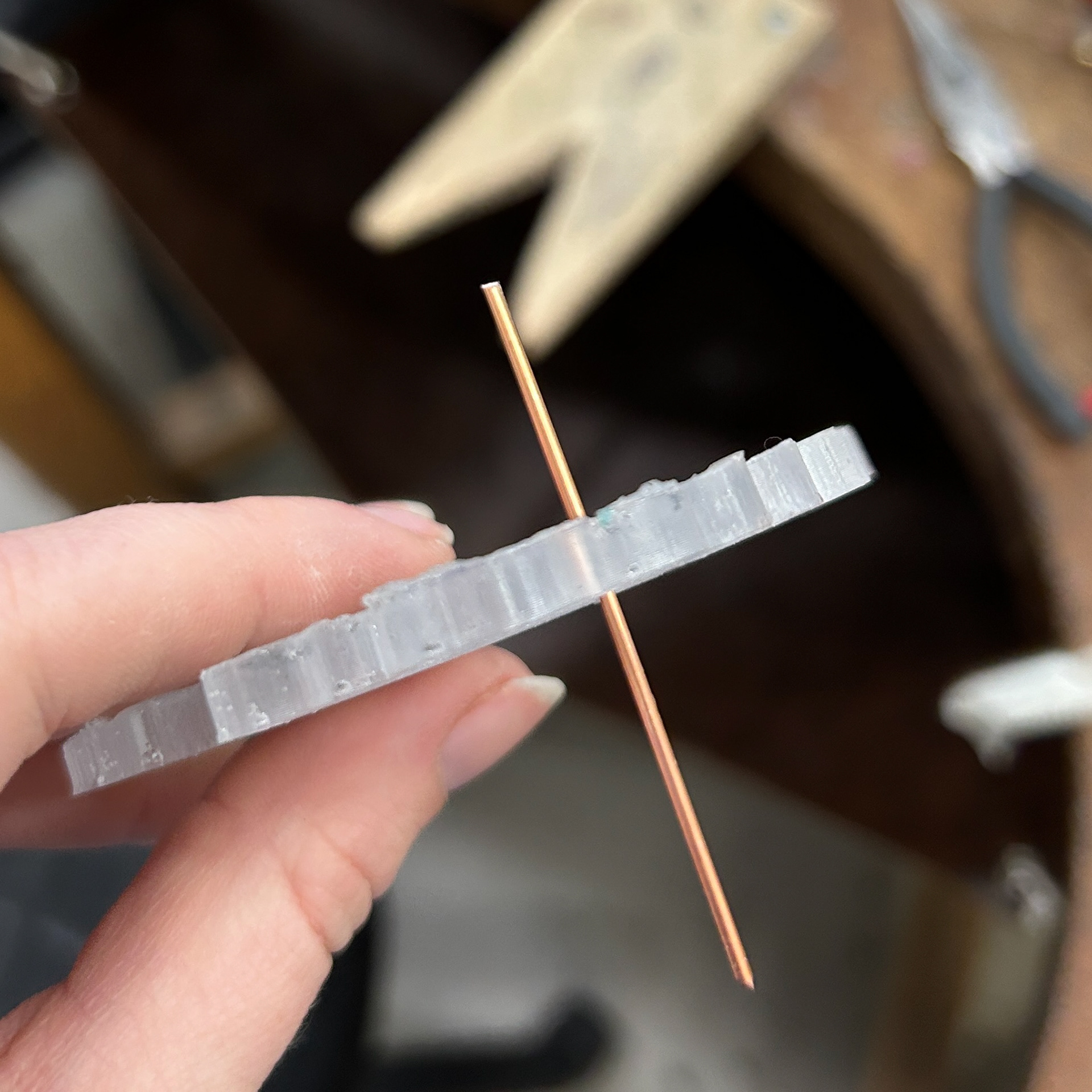
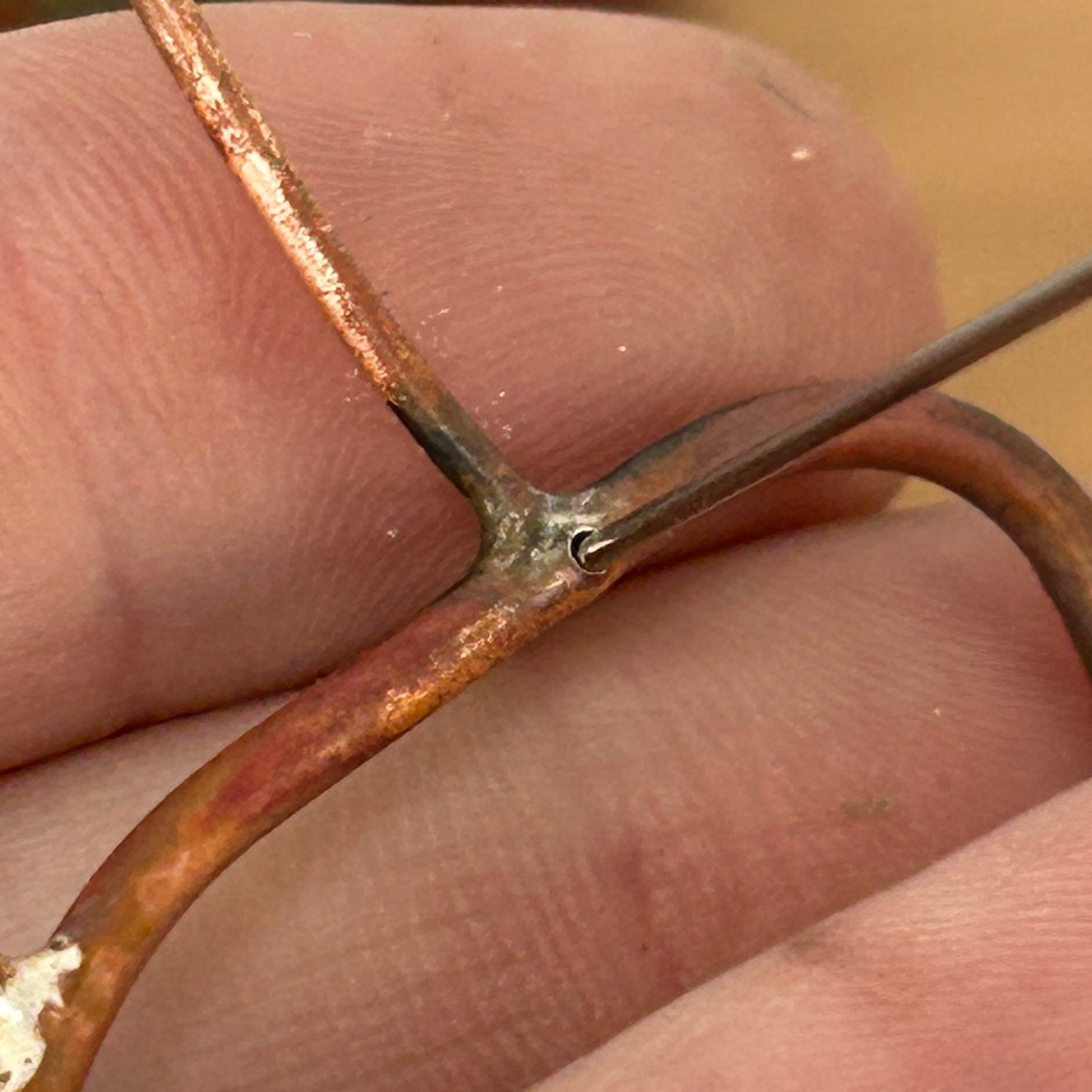
I then had to drill holes into the wire to allow the brooch wire to pass through. I unfortunately kept missing the centre punched hole on one side, and found that filling the profile of the wire made a huge difference which is what I did on the other side.
I then tested the fit of the wire, which fit well. I placed the wire in place and then threaded on the rest of the bezel, which allowed me to mark where the prong needed to be for the brooch hook. I then soldered that on using easy solder.
I was really happy with how this brooch mechanism looked. It didn't distract from the rest of the brooch and blended in with the rest of the wire used. Surprisingly, I also liked the long prongs I had kept on the front. This was not intentional, and I had purely kept these because I hadn't cut them down yet. As Patricia pointed out, this looked almost like the metal was growing over the rest of the piece, which I quite liked. While I'm not sure if this would work on every piece, it is definitely something I can test first by digitally drawing over the shapes before cutting the prongs to see which version I prefer.
Fixing the Application of Resin
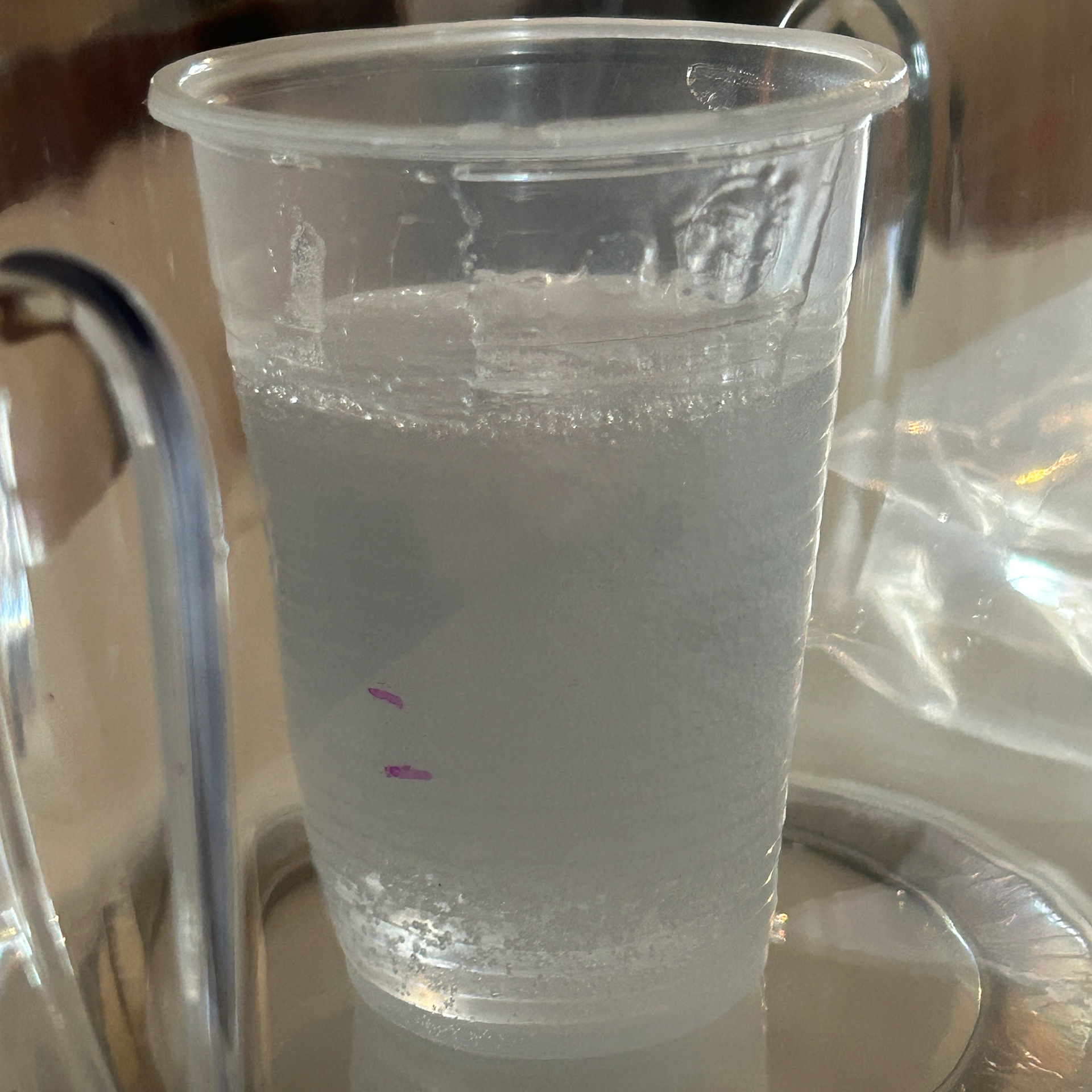
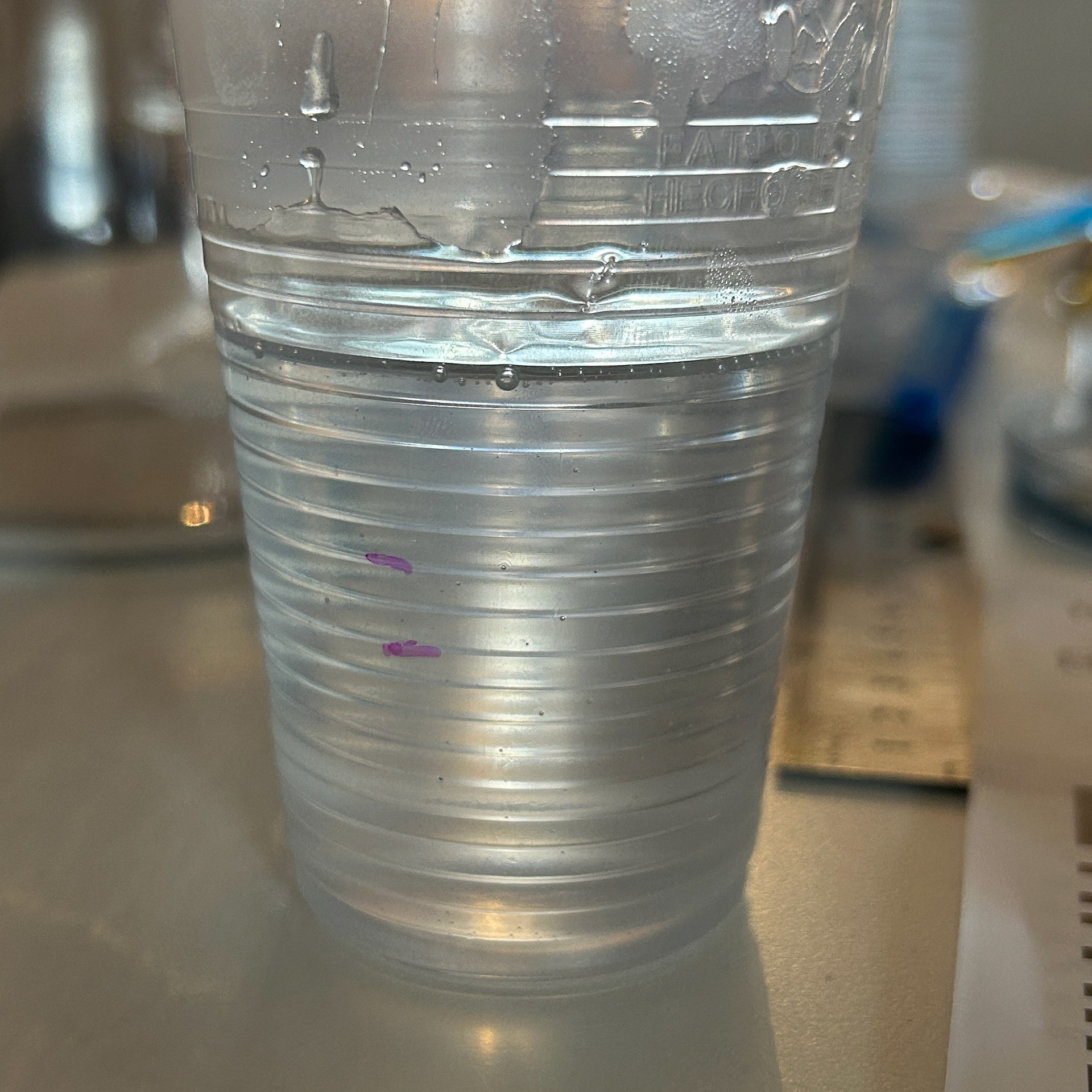
To fix the application of resin and help remove any bubbles, I invested in a resin vacuum. While it added around 15 minutes to the prep time, it was definitely worth it. I tested this on some of my bacteria plates first, which was very successful.
I then moved on to fixing the resin on the 3D agar piece. Initially, I had been using a mould which was much too big for the actual piece of agar. I had an idea whereby I pour UV resin over the piece, and cure in between each layer. Then I could flip the piece over and cure a layer on the back to seal the piece.
I knew that I would need to place the piece on something that wouldn't stick, so I first tested this with the back of a resin mould, with the intention that I would file away any excess resin with my dremel. After curing the resin, I released that this would be very time consuming. From this, I then changed my approach slightly.
I decided to use part of an old petri dish lid to elevate the piece of agar, and let any excess resin pour off the edge. This worked well, and so then I flipped the piece over and used the original silicone mould I made this piece with as support.
There is still a lot of refinement needed for this piece, however, the idea worked. Next time, I am going to try cutting up pieces of silicone to hold the piece in place, as the plastic got stuck and took force to remove, resulting in the agar getting slightly damaged. I would also like to add a couple more layers to the agar, just to make it slightly thicker and remove any chance of gaps in the resin's coverage.
Making a Final Prototype
After testing the application of resin, I then moved on to making a prototype of my brooch. I first made a new silicone mould using a new CAD model with a thicker profile for the wire.
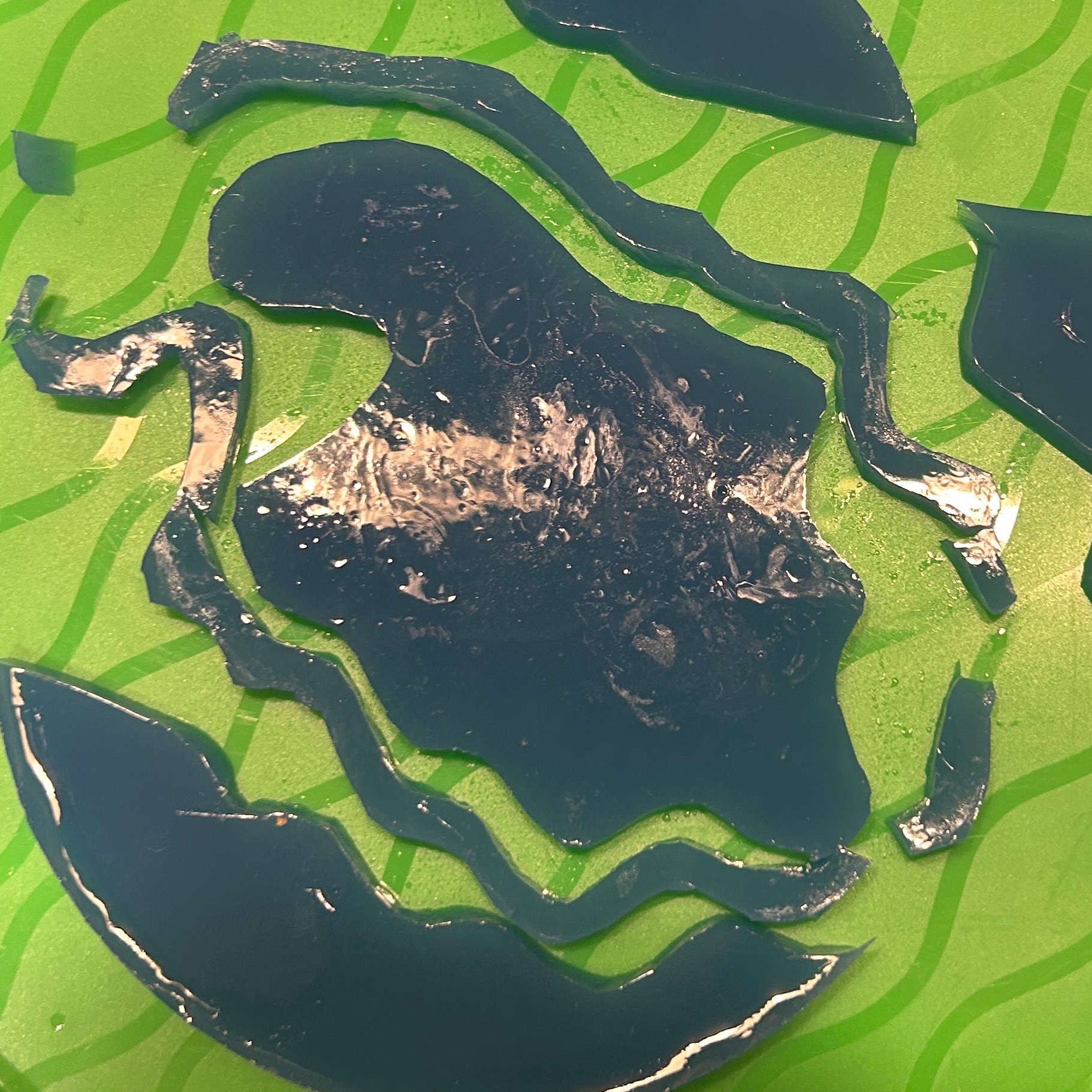
I also tested a new way to make the agar the correct shape. I used a petri dish to create a flat piece of agar, cleaned the 3d piece in order to make sure no microbes were being transferred, and cut out the shape. I then cut the shape again, to leave the desired thickness of resin I wanted around the piece.

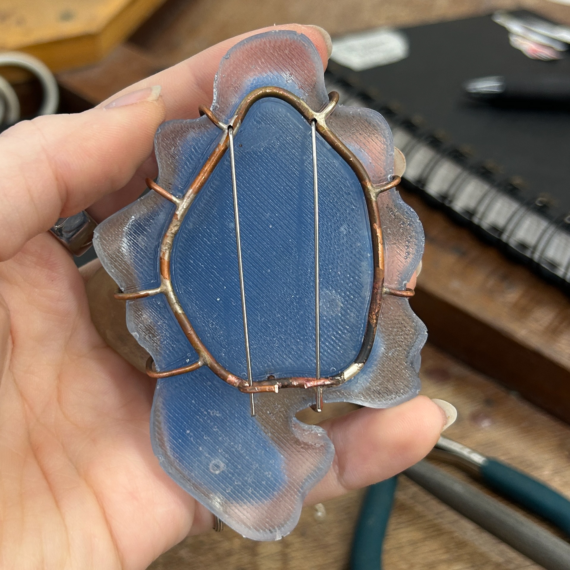
I then went into the metal workshop to make another bezel using copper, using the same methods as before.
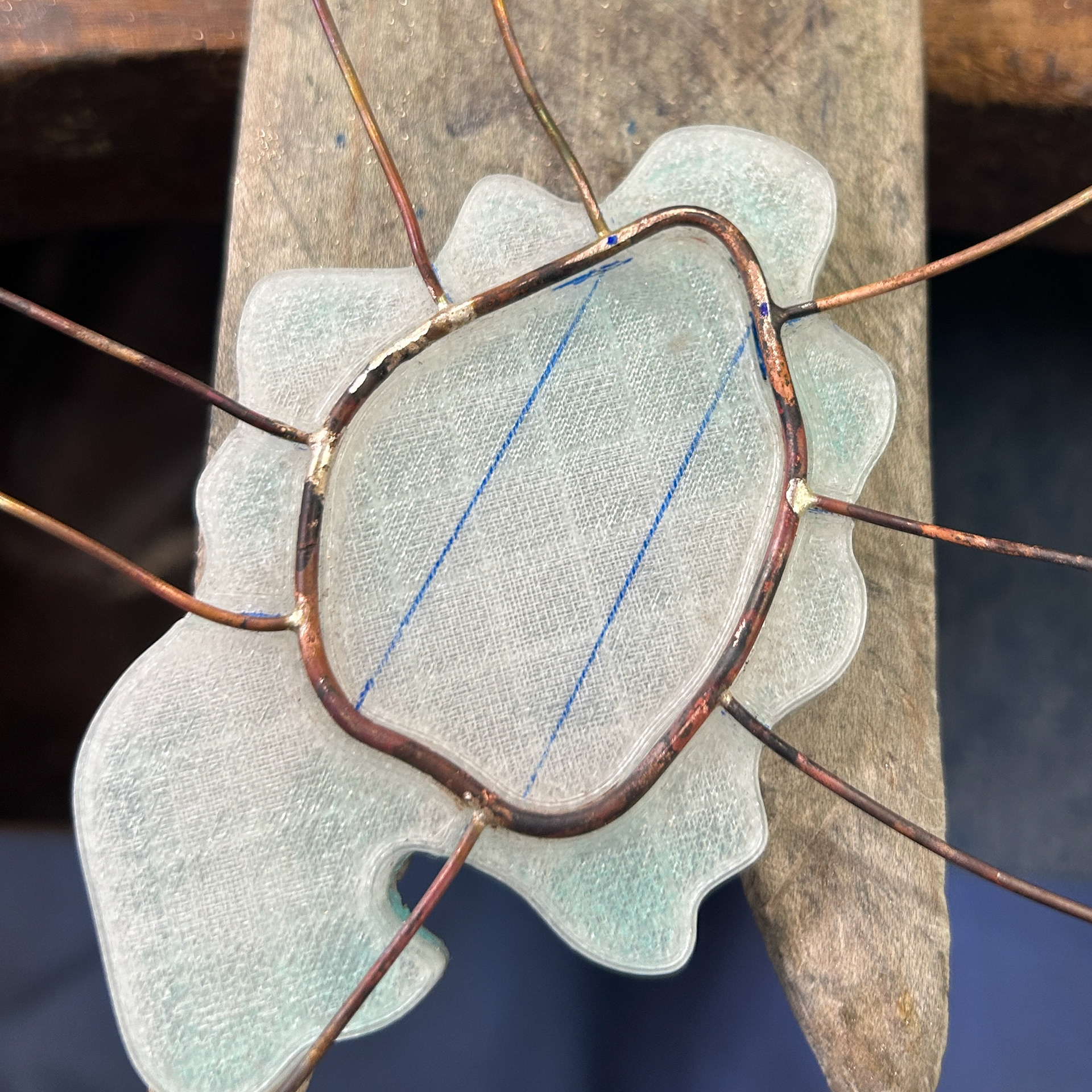
To assemble the piece, I used a combination of different grade solders in order to reduce the risk of previous solders melting. I then filed the wire and drilled a hole into the wire for the brooch pin. After checking the fit of the brooch pins, I bent them over vertically in order to mark where to solder the hooks. I then soldered these hooks on using extra easy solder.
I then had to solder on prongs that would extend through the blue agar and onto the front, to allow for the 3D agar to be glued on. I knew that in my final pieces, I would be marking out these drill hole using Rhino, and cutting a space for the hole in the agar. This meant that after I had drilled the holes, the edges of the agar would not be exposed to the metal; however, for this sample, I did not do that.
Finally, I pushed over the prongs and left them longer to see what the tutors thought about the longer prongs. While I wasn't a fan of them myself on this particular piece, I wanted another opinion.
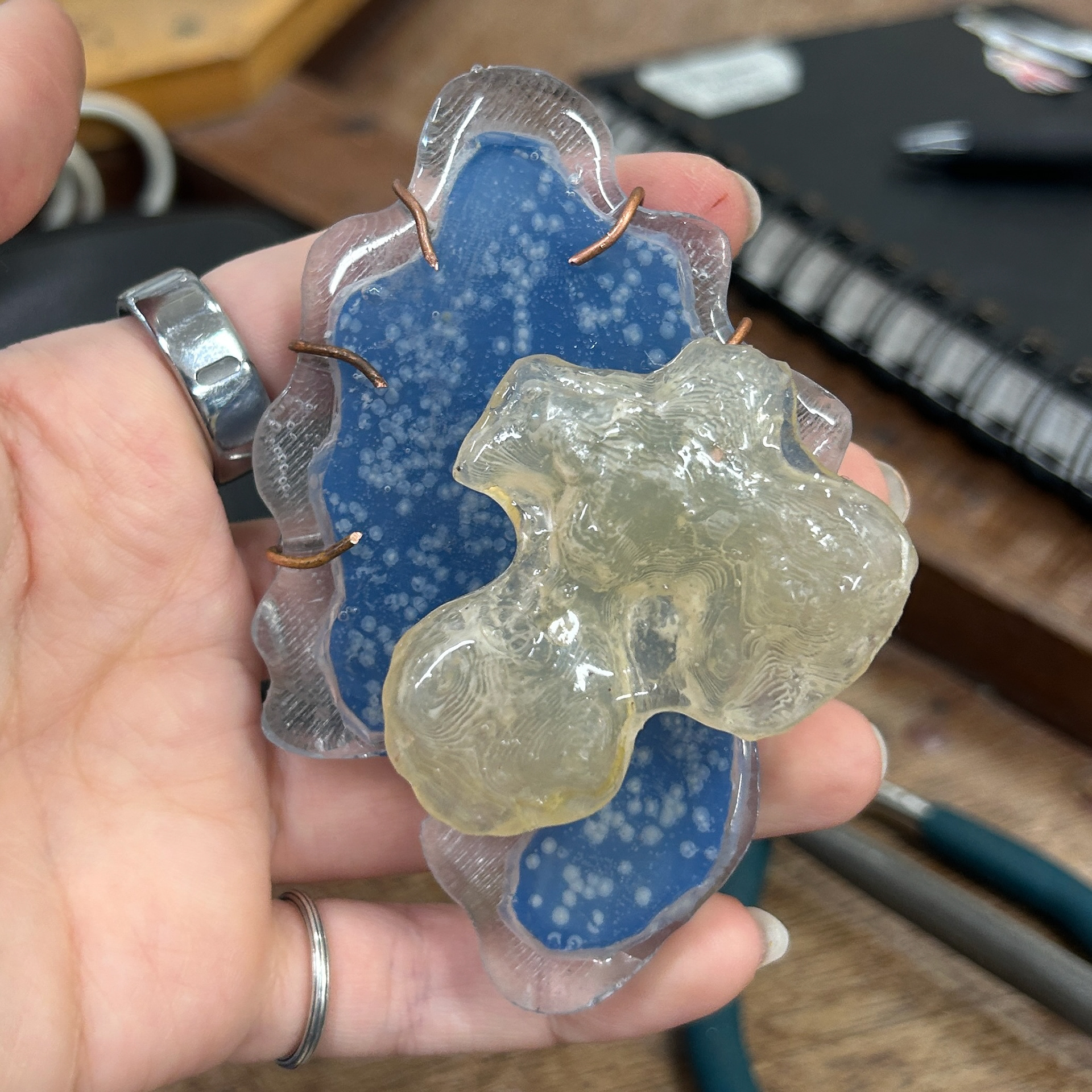
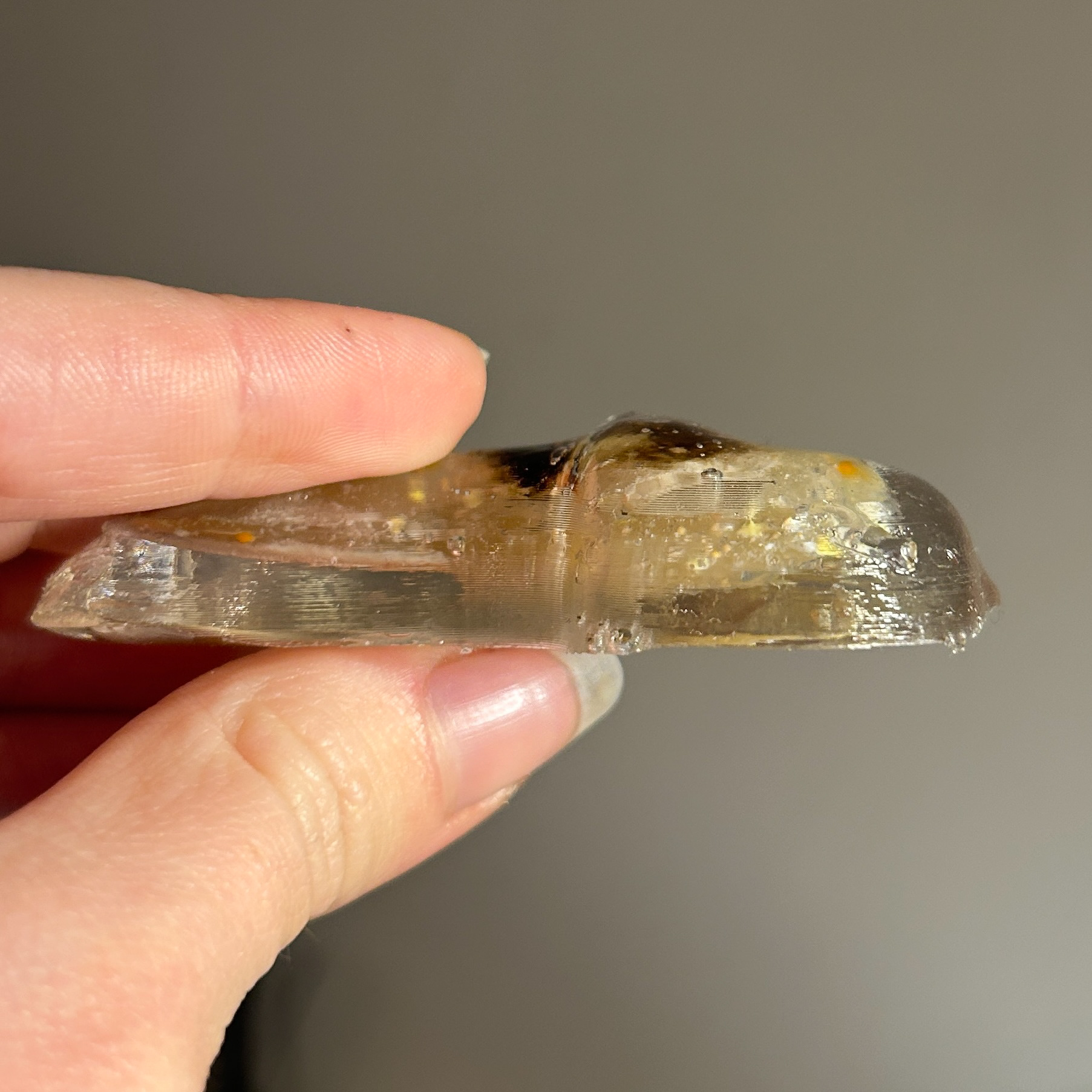
While I was not happy with this outcome, it did teach me a lot. The movement and the shape of the agar were my main concerns, as this was the focal point of the piece. I needed to figure out a way to make the shape of the agar perfectly fit within the resin mould and reduce the movement of the agar.
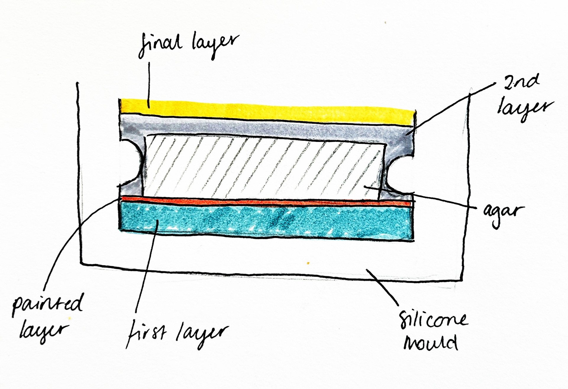
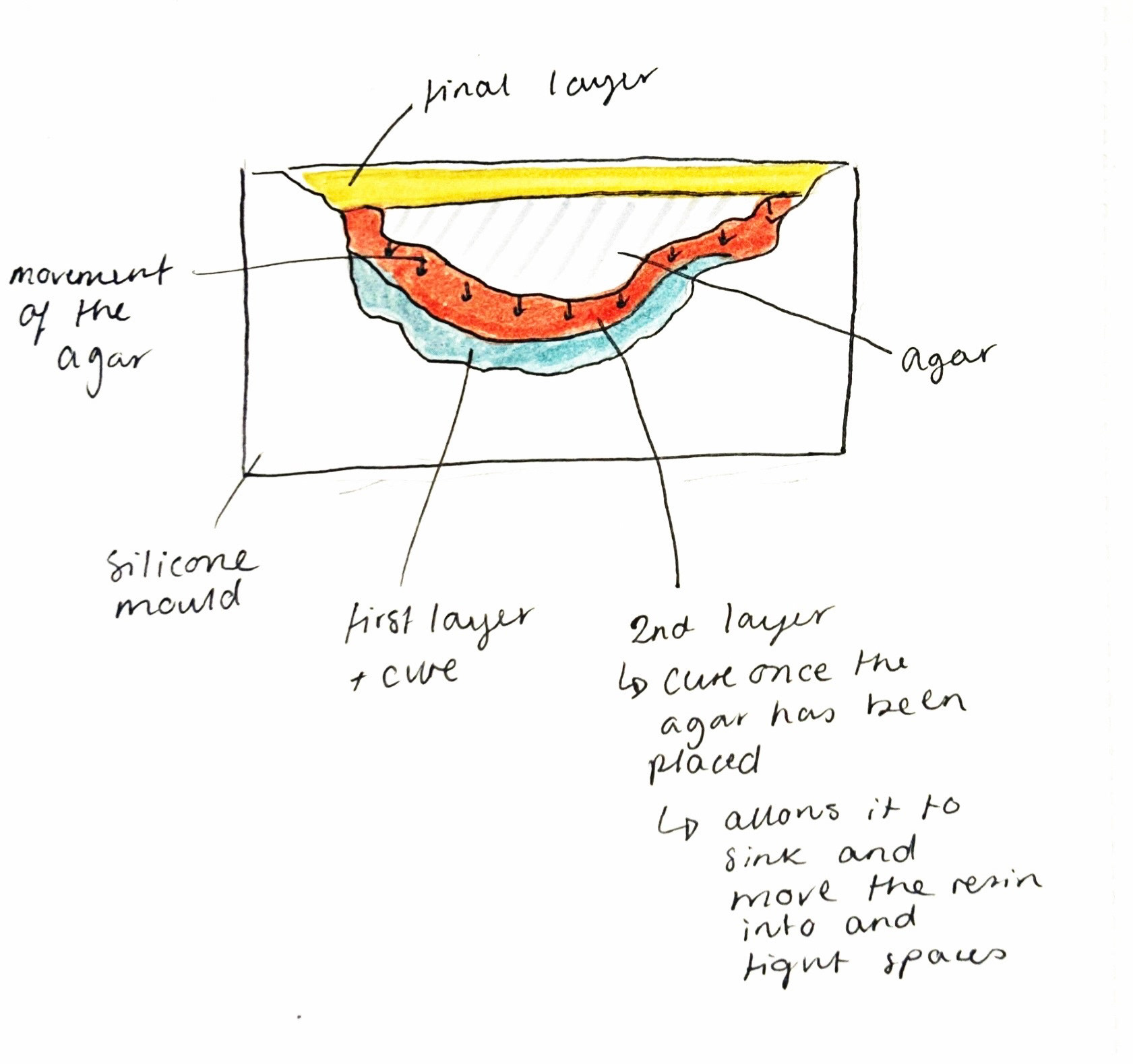
Diagram from Unit X
The agar had shifted upward and sideways while the resin was curing, and I think I understand why. I used the same application method as I did during Unit X, where I painted on a thin layer of resin to act as an adhesive between the first and second layers. This time, however, I suspect that layer was much too thick, which allowed the agar to move upwards. As well as that, I always cure my resin in a warm environment, as that’s where I’ve had the best results. But in this instance, I believe the surface beneath the mould was uneven. Combined with the thicker resin layer, this likely caused the movement.
Now that my room is warmer, I am able to cure the resin in my room, where there is a flat surface. This and a thinner layer of resin should be much better for the curing process.
From the formative review, we spoke about how my 3D prints needed refining, especially with the inset pieces for the prongs and the bezel, as well as ways to make agar fit better within the resin. This is explained further in my 'Research and Development' page.