Preparing the Agar
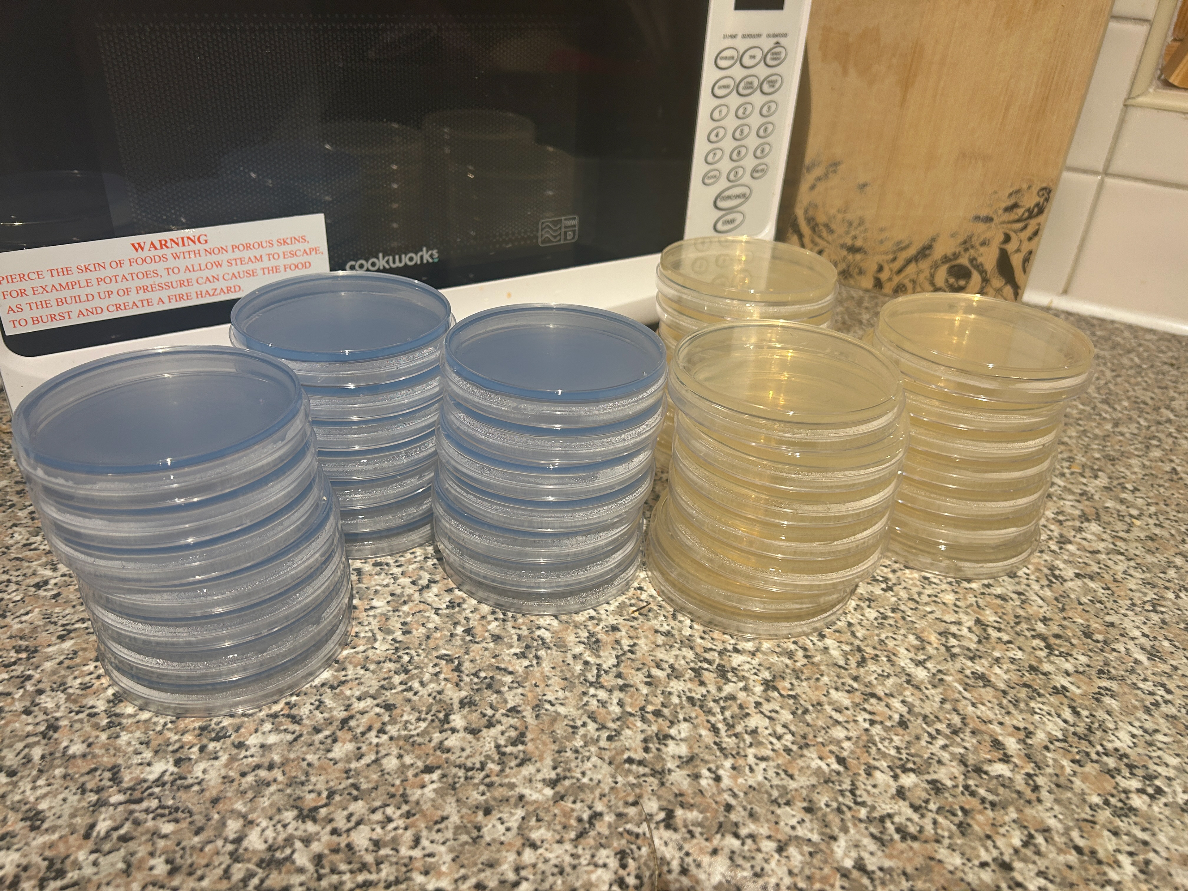
To start making my final pieces, I needed to make Agar dishes to grow the bacteria. I knew that I wanted to have 3 sets of bacterial growth for each day as this gave me the chance to pick which growth patterns were best. At this stage in the project, I was using both dyed Potato Dextrose Agar as well as Nutrient Agar. This meant I had to make 21 plates of Potato Dextrose Agar, as well as 21 plates of Nutrient Agar.
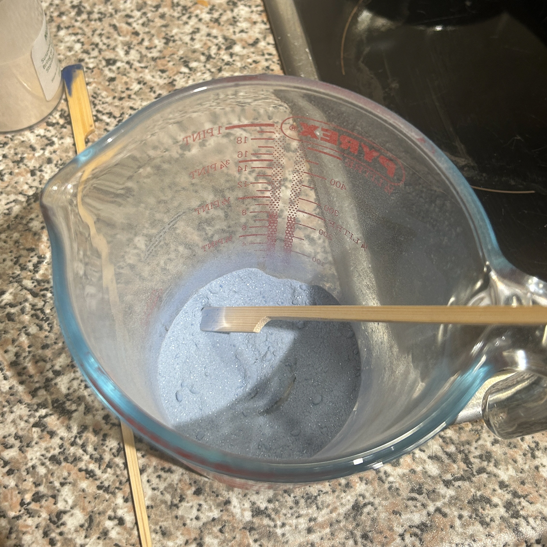
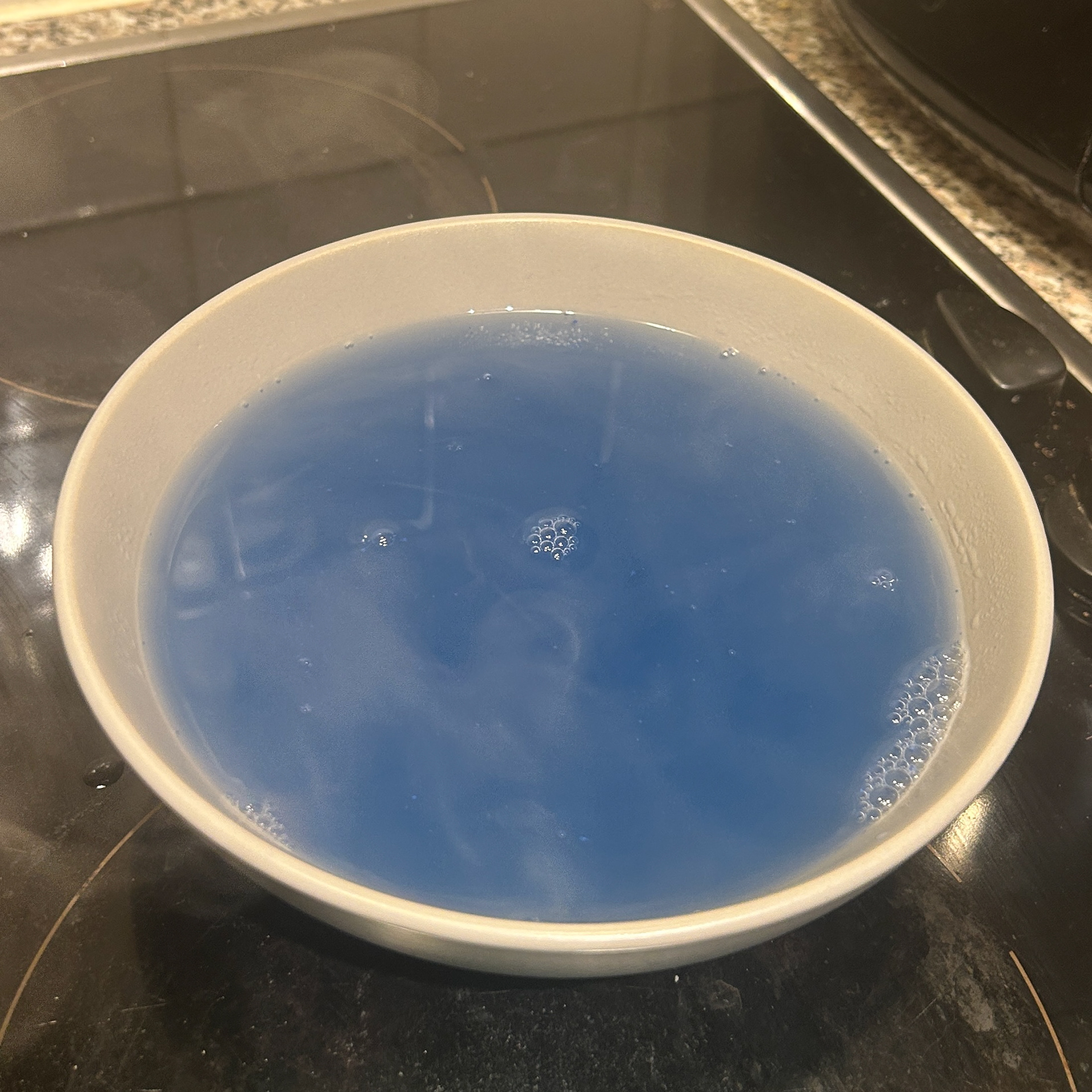
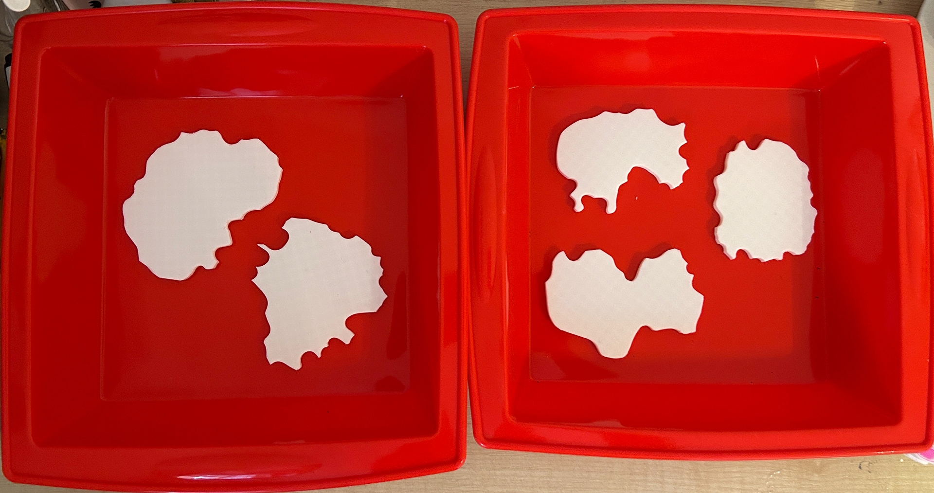
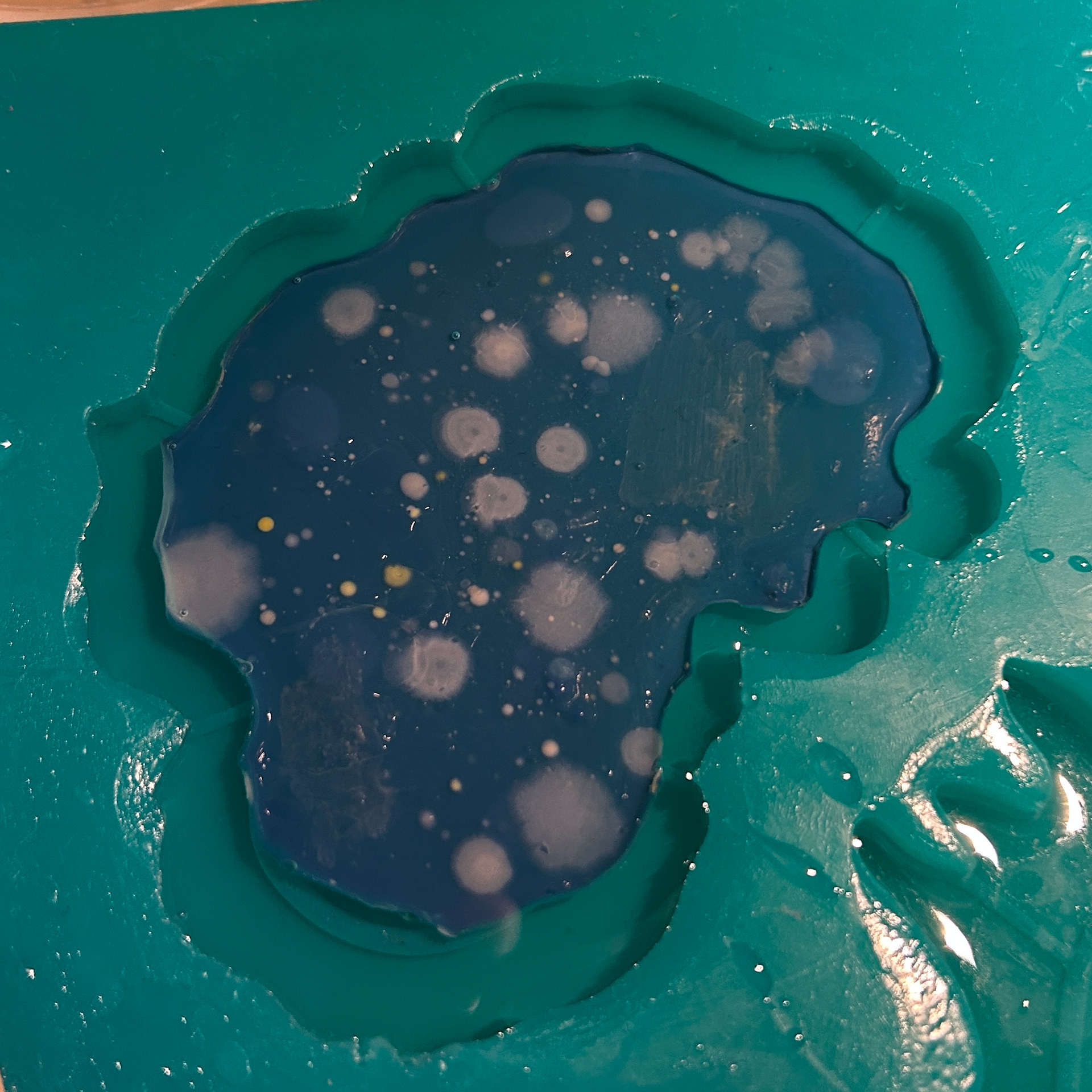
While I was dyeing the Potato Dextrose Agar, I found that I had added too much pigment to the first batch and that it had clumped together, resulting in an uneven colour. I redid the batch and poured it into the plates.
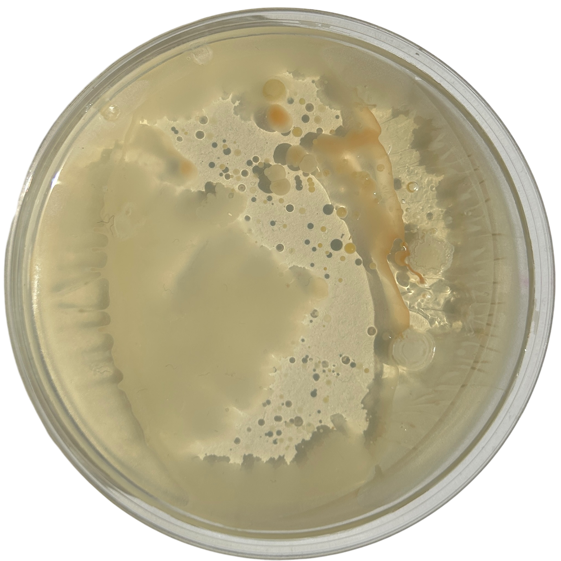
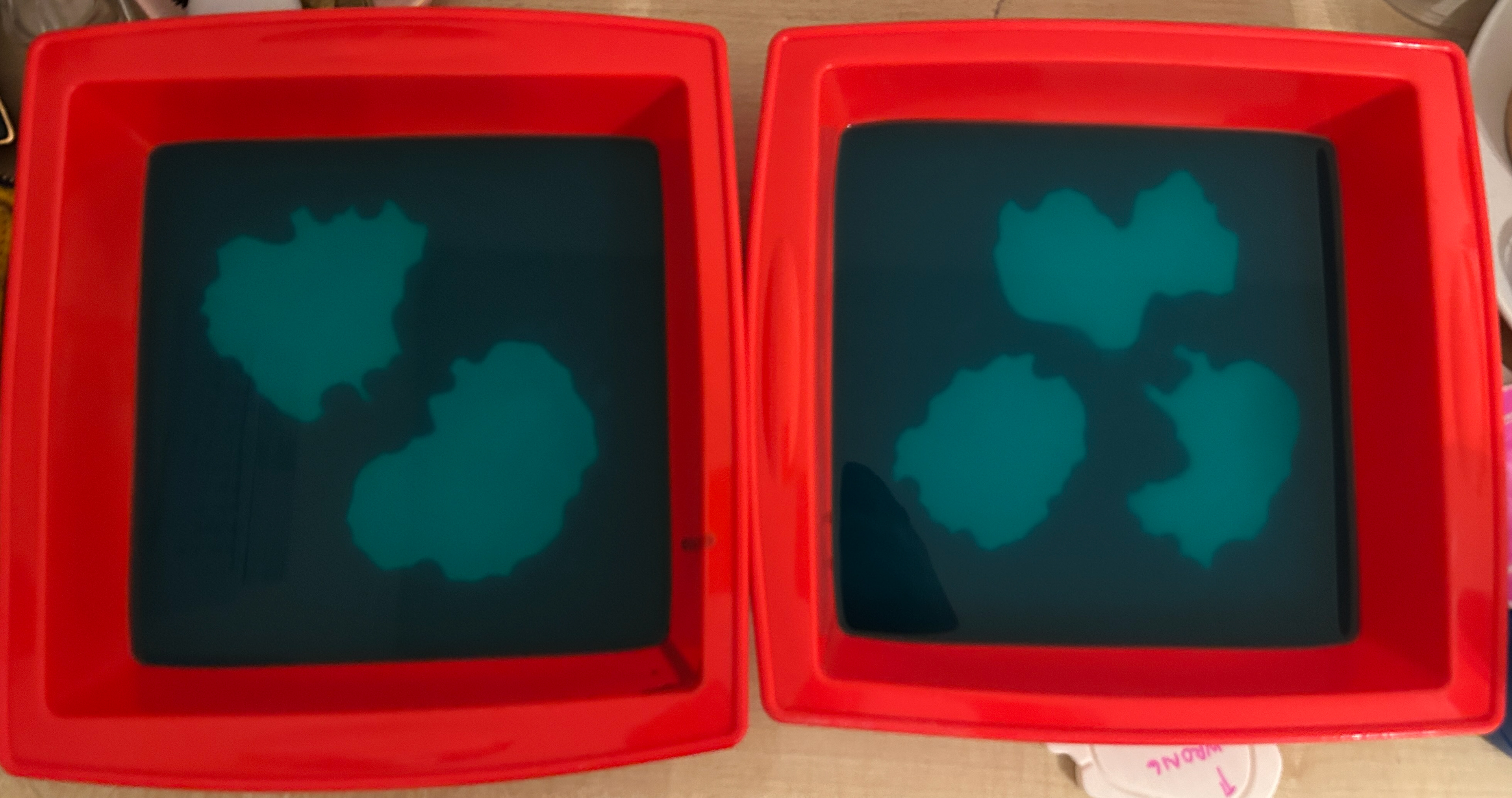
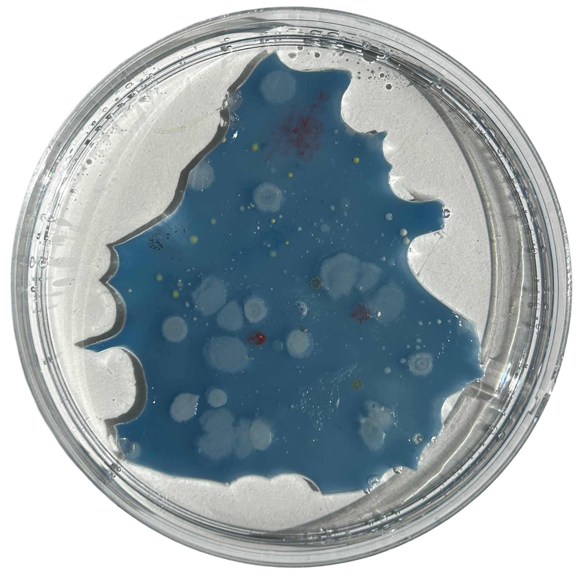
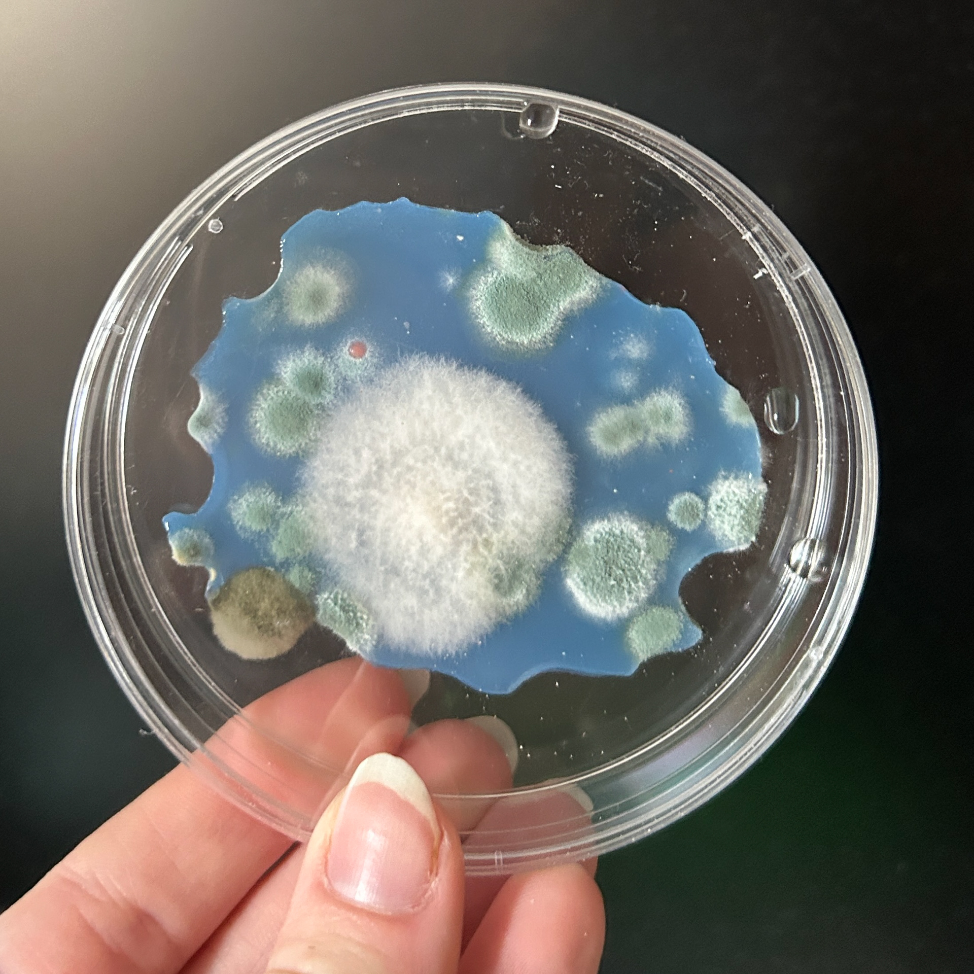
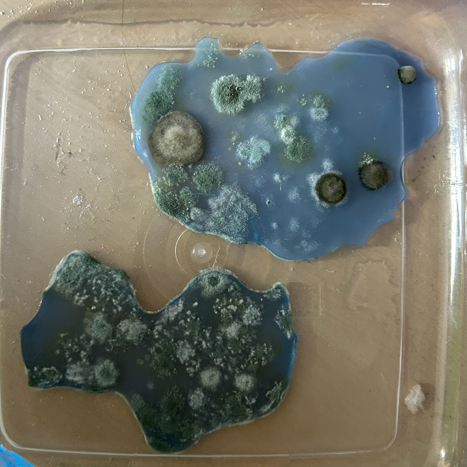
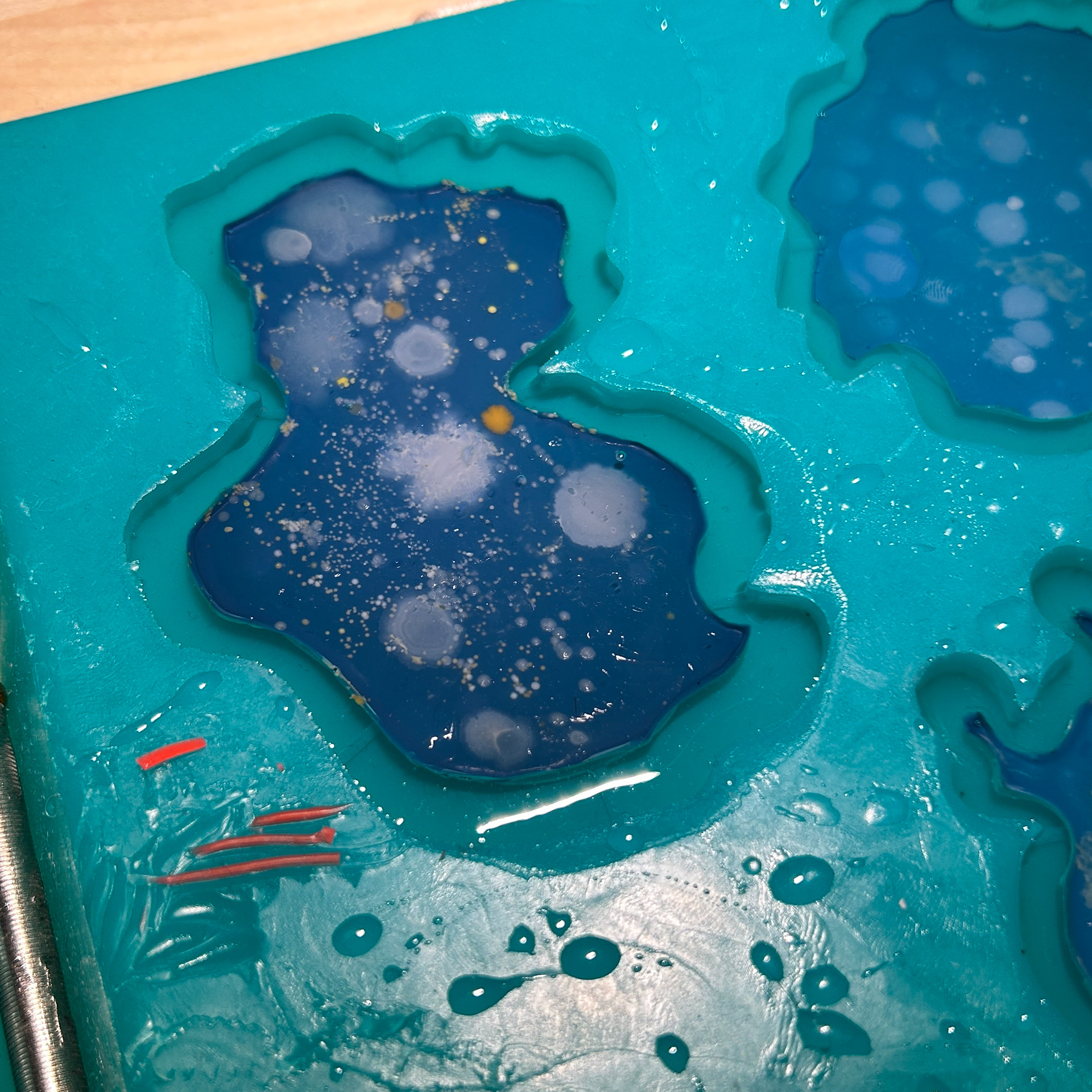
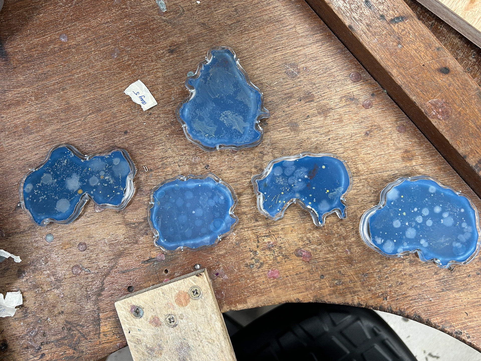
While the dying wasn't necessarily needed for this stage, as these would not be the final brooches, I wanted to use pigment in these plates in case there was any effect on the bacterial growth. As I wanted to use the blue pigment on the final brooches, I felt as if keeping it all consistent was important. For some of the blue plates, I found that the dye faded slightly with the lighter colour. This can be clearly seen in 'Day 2'. While it had no effect on the bacterial growth, it has made me question if more dye is a safer option.
In my final agar pieces for the brooches, I do end up using a slightly darker blue colour. I realised that this deeper blue was more complementary to the colours of bacteria that grew on the potato dextrose agar, and posed less risk if fading.
Waste agar
Agar Results
Initially, I planned to swab three bacterial samples per day. This was intended to give me contingency in case some plates didn’t grow or became contaminated before swabbing, ensuring I’d have enough viable samples to work with. However, before I began the process of swabbing, I realised that the total number of plates would not fit in the cupboard where they would be incubated. This forced me to reconsider my approach, and so I decided to reduce the number to two plates per day. While this reduced the volume of data, it allowed me to maintain consistent conditions for growth and avoid compromising the integrity of the samples.
At this stage, I was still using bacterial growth patterns from nutrient agar to inform 3D agar models as the front piece of my final work. However, as discussed in Research and Development, Formative Review 2, this idea was ultimately dropped. Despite this change, I continued growing the samples. This was partially because I had already committed to the process, but it also became a point of interest for me, and so I wanted to finish the samples. The decision to complete the sampling was less about necessity and more about following through on an investigation, even if it no longer needed the final design.
(Physical samples labelled as eg. day 1.1 or 1.2 to correspond to each row)
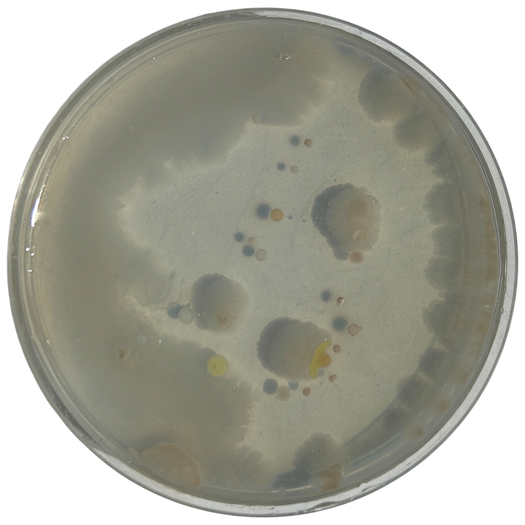
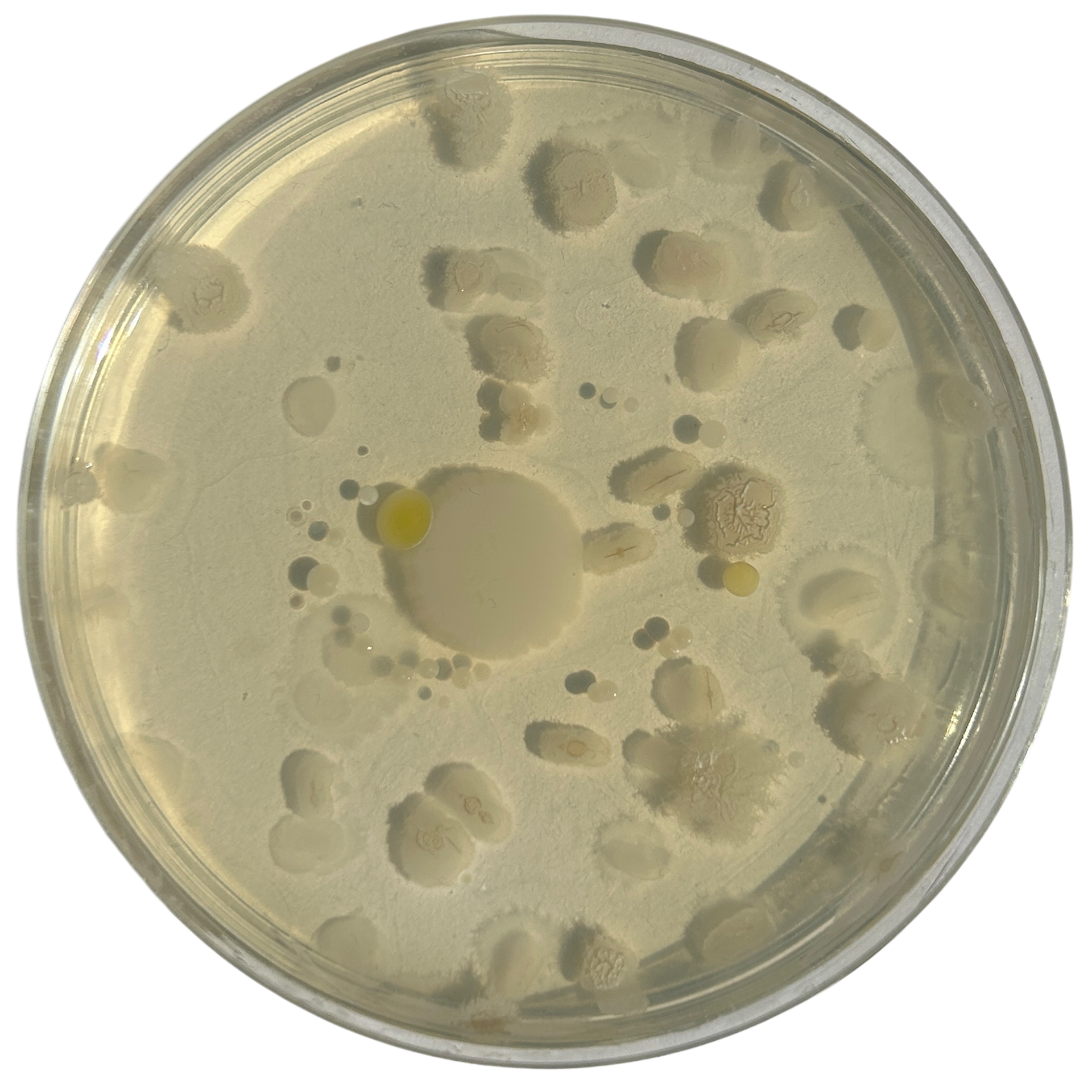
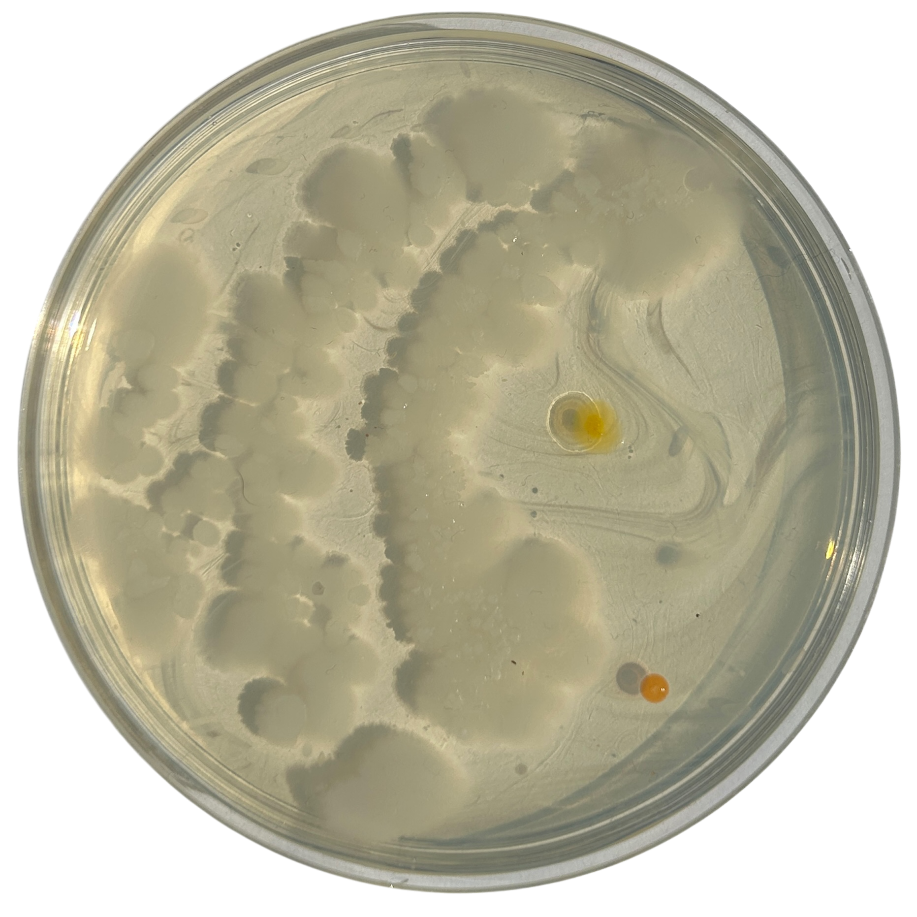
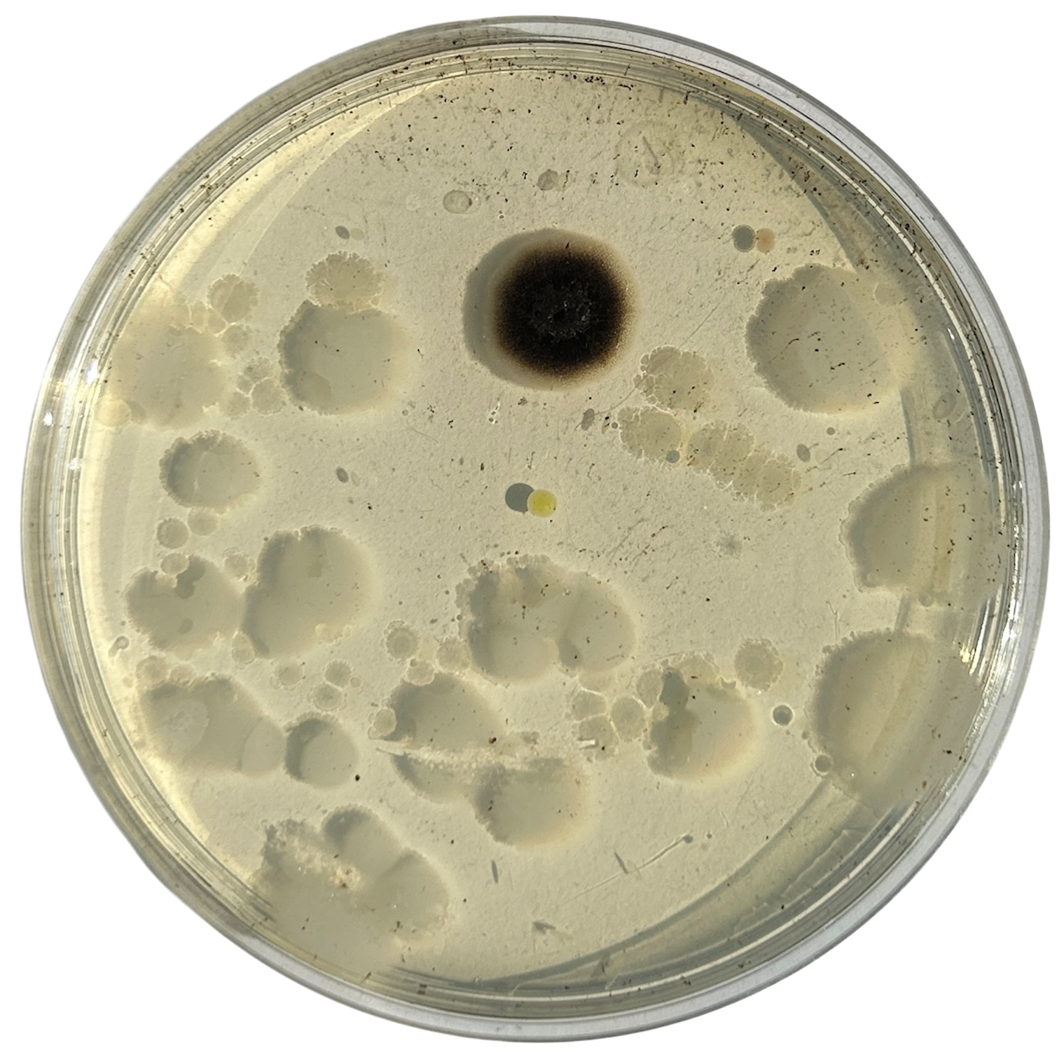
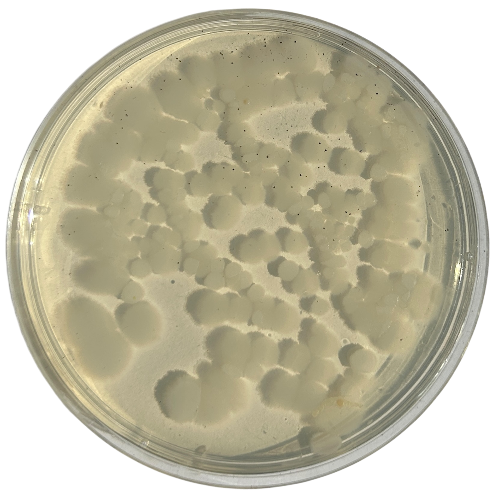
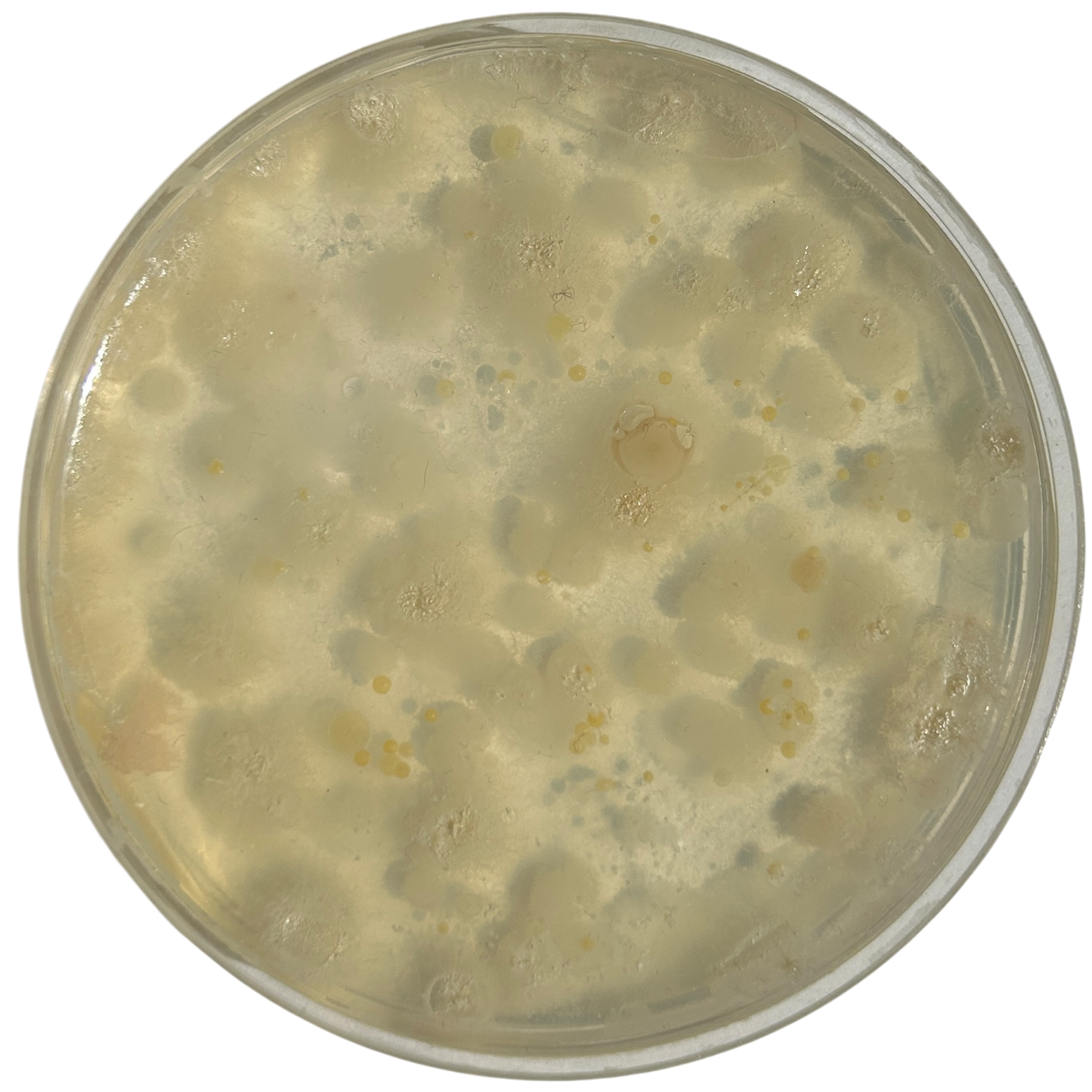
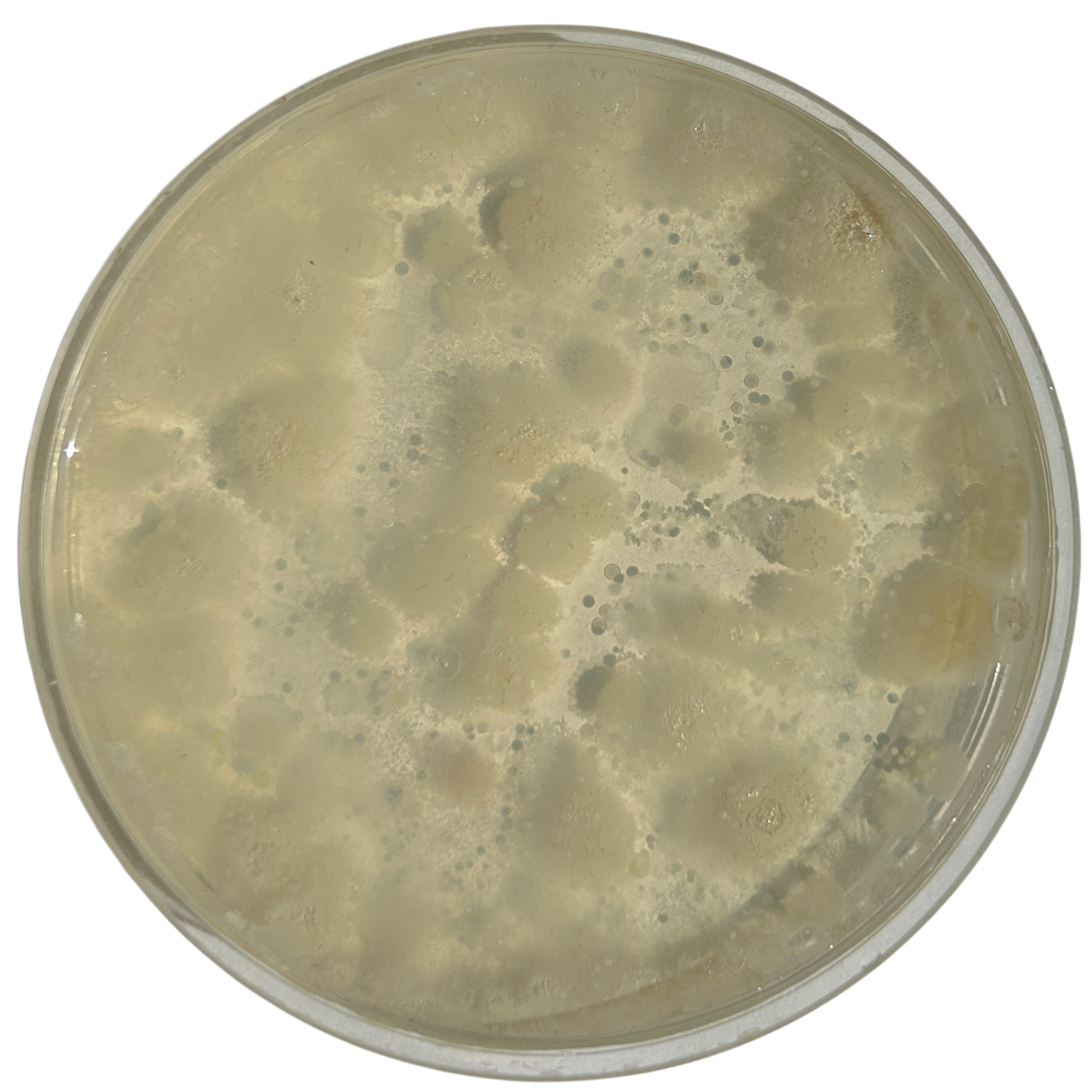
Potato Dextrose Agar

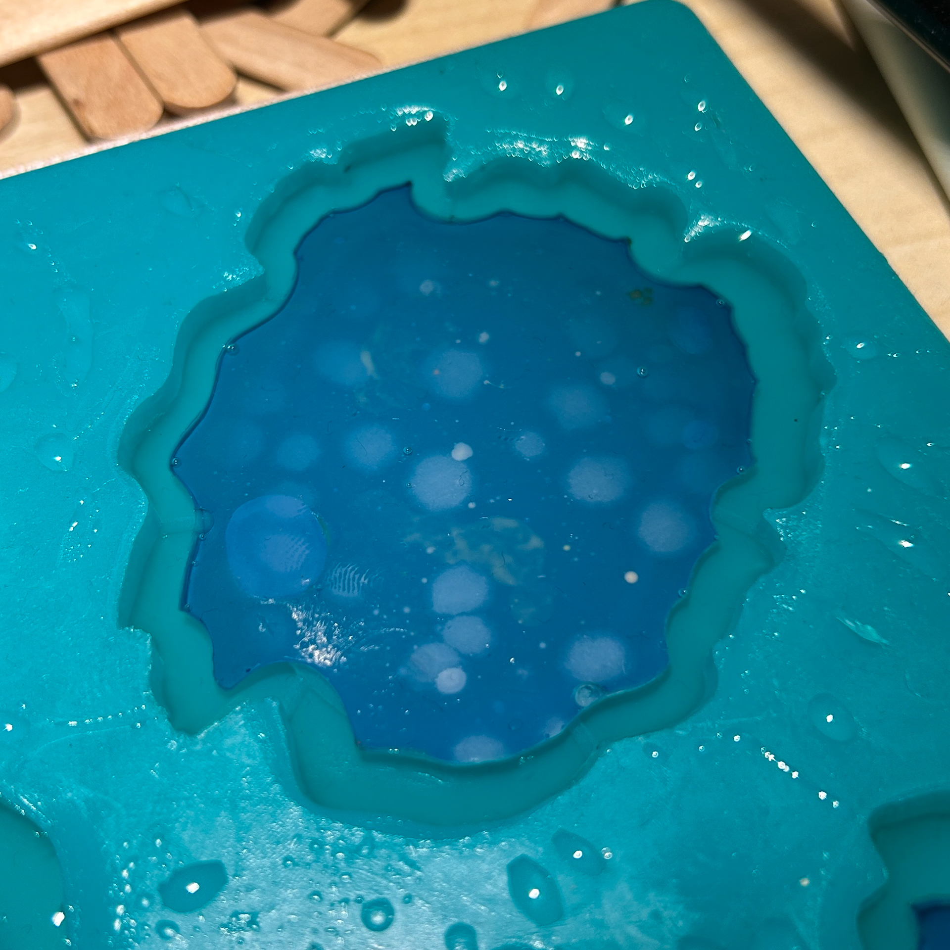
Day 1
Day 2
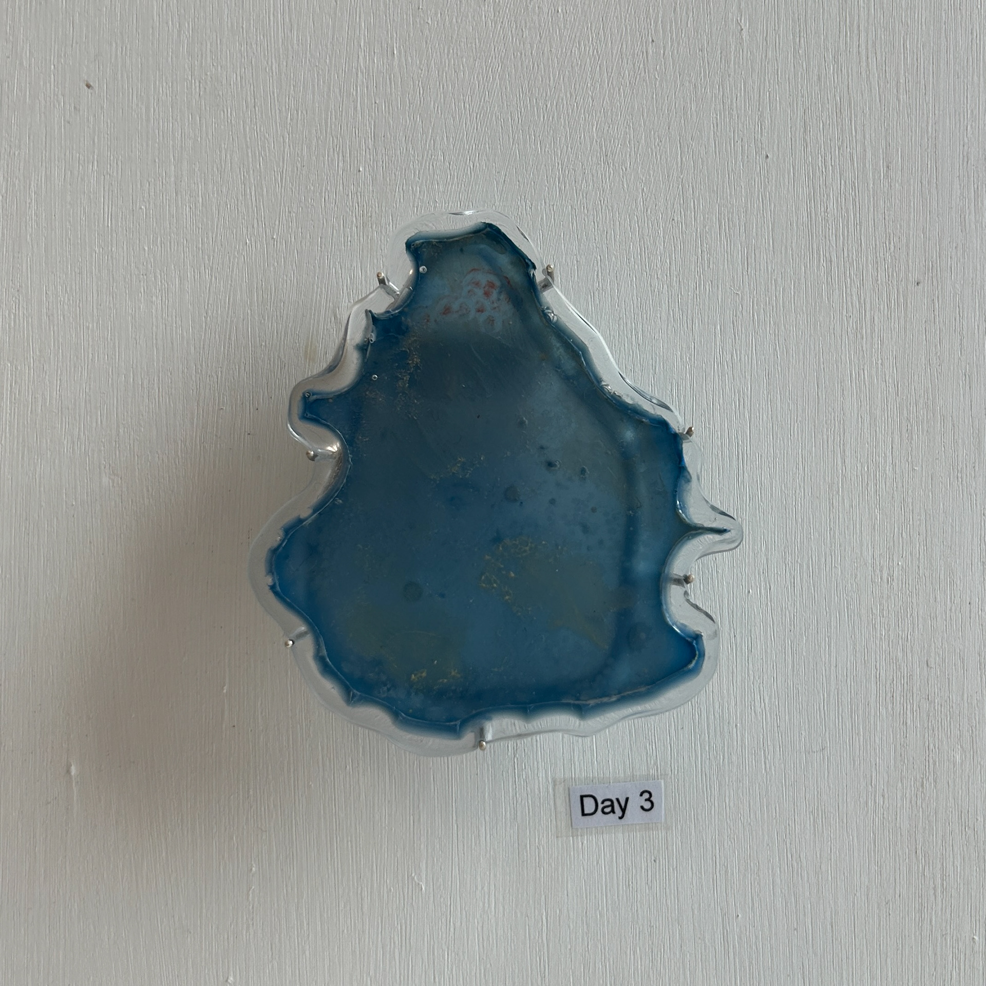
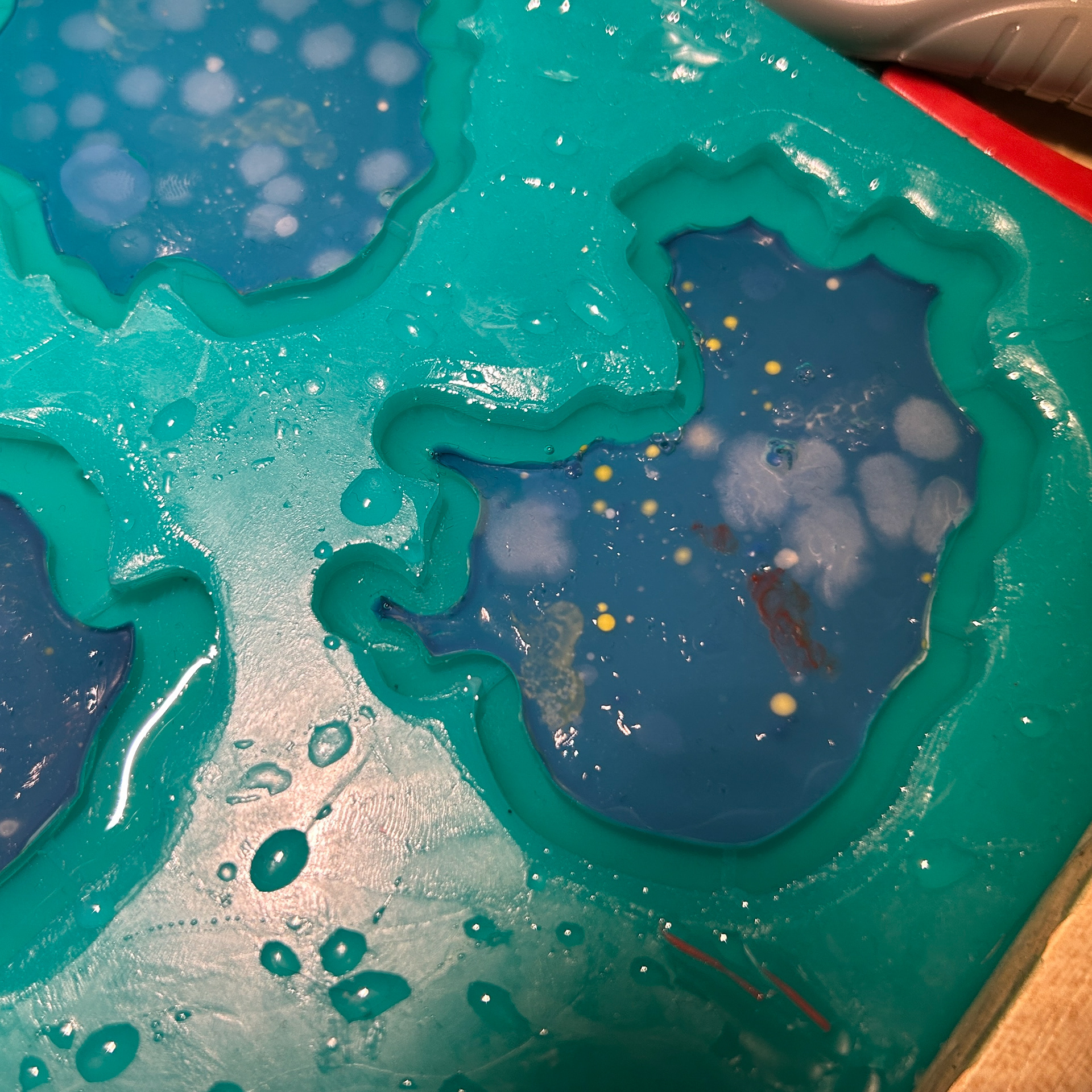
Day 3

Day 4
Day 5
Day 6 - For Context Video

Day 7 - For Context Video

Day 1
Day 2
Day 3

Day 4

Day 5

Day 6
Day 7
Nutrient Agar

Day 1
Day 2

Day 3
Day 4
Day 5
Day 6
Day 7
Day 1
Day 2

Day 3

Day 4
Day 5

Day 6

Day 7
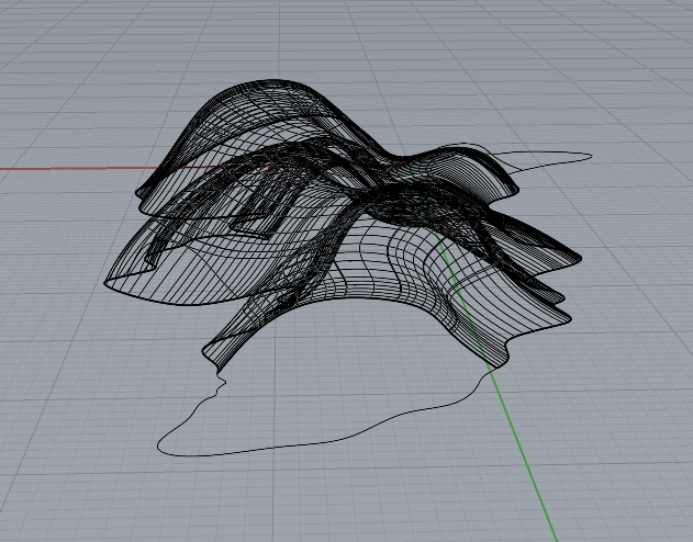
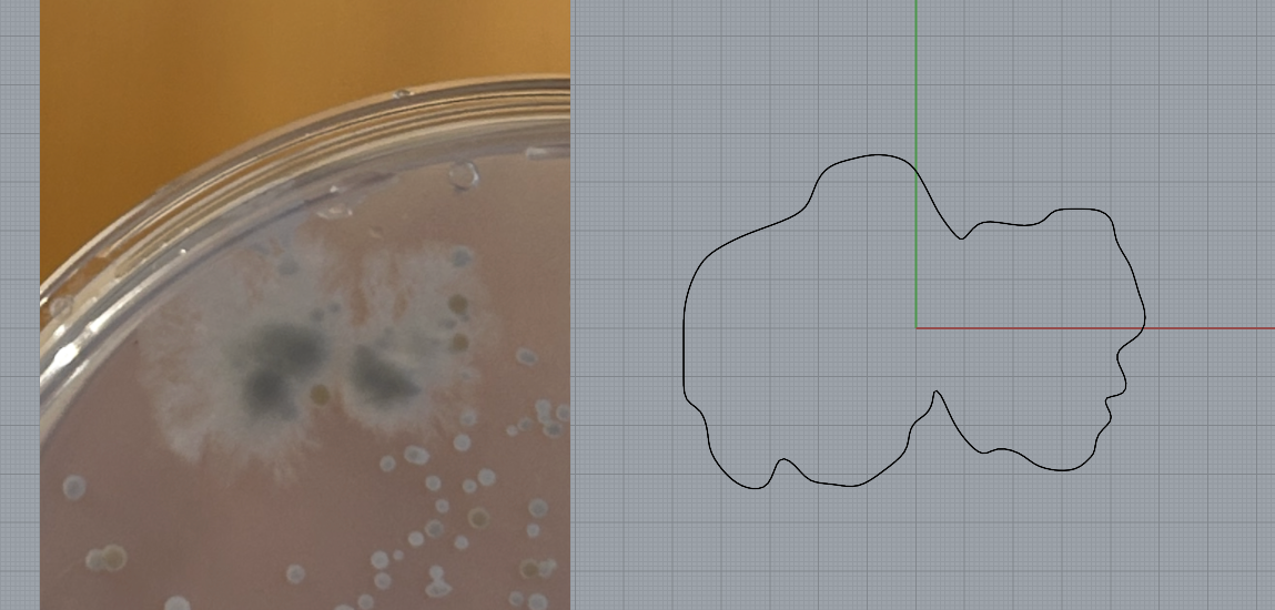
I picked the shapes from each day that I liked the most and moved these into CAD.
CAD Models
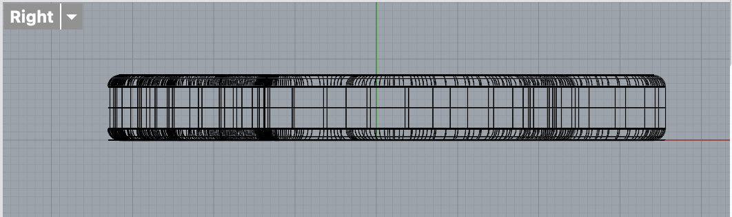
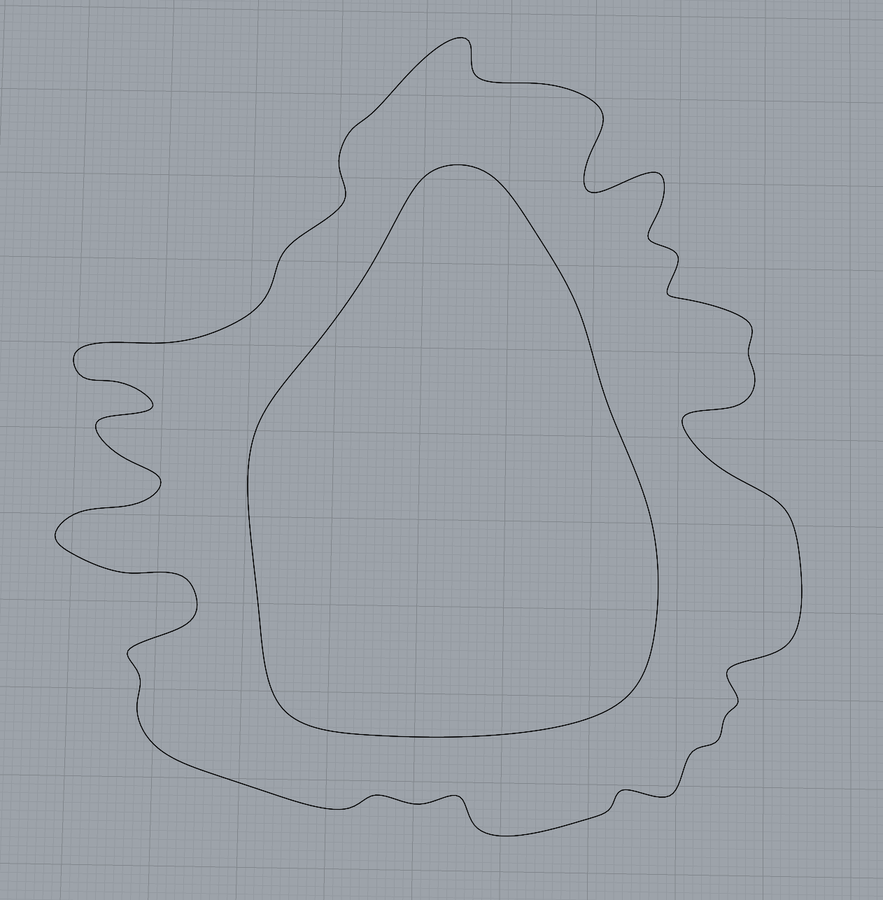
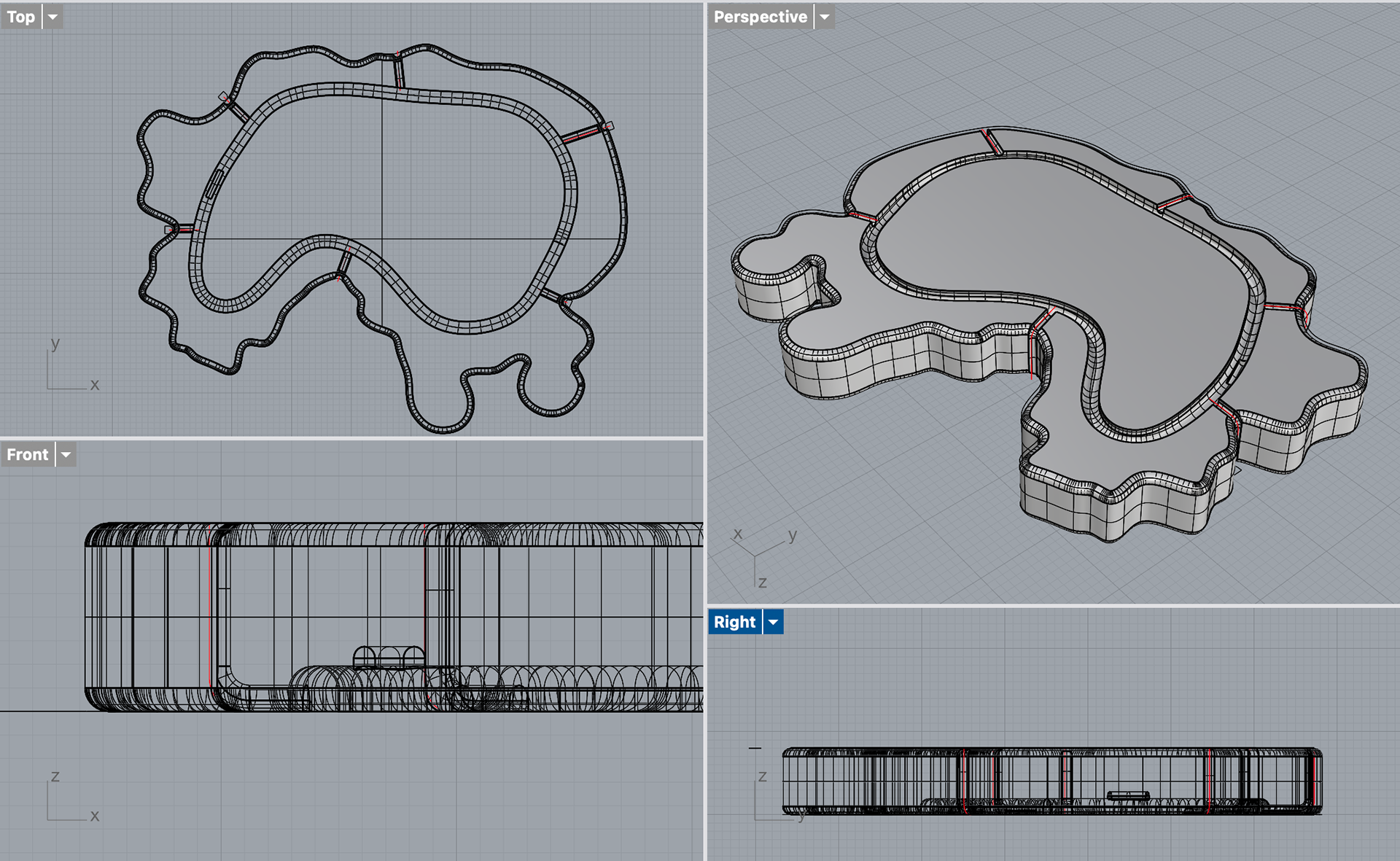
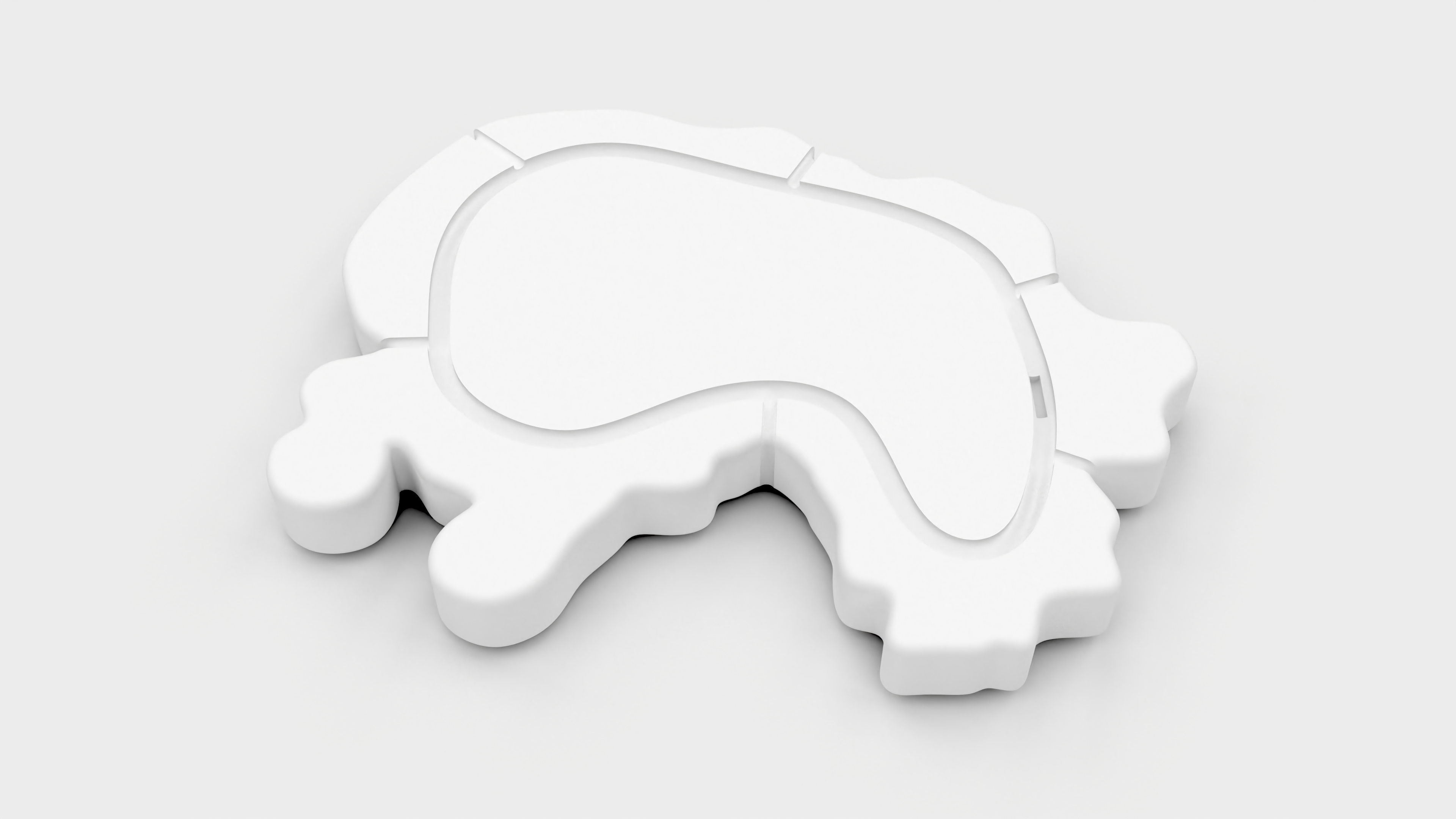
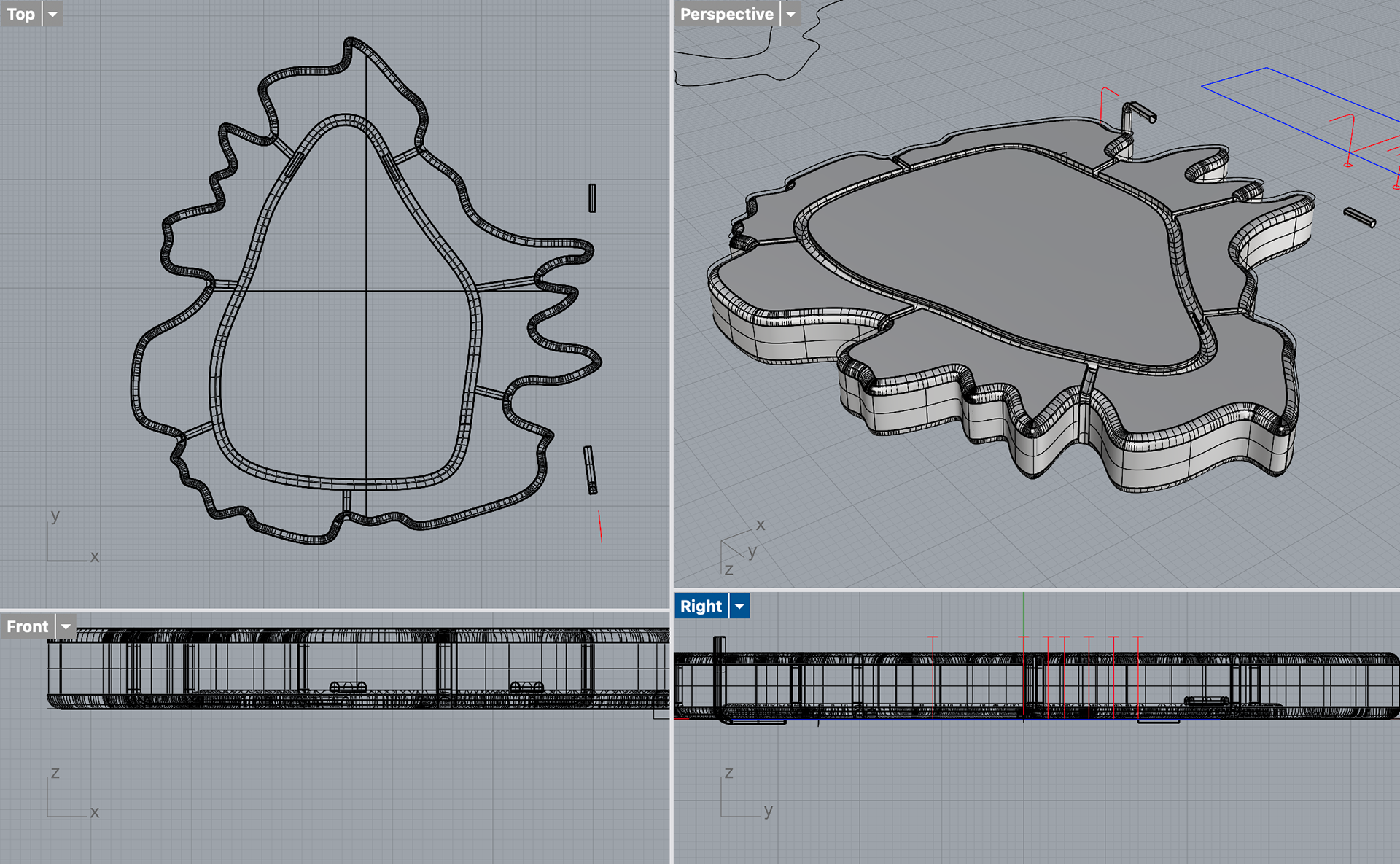
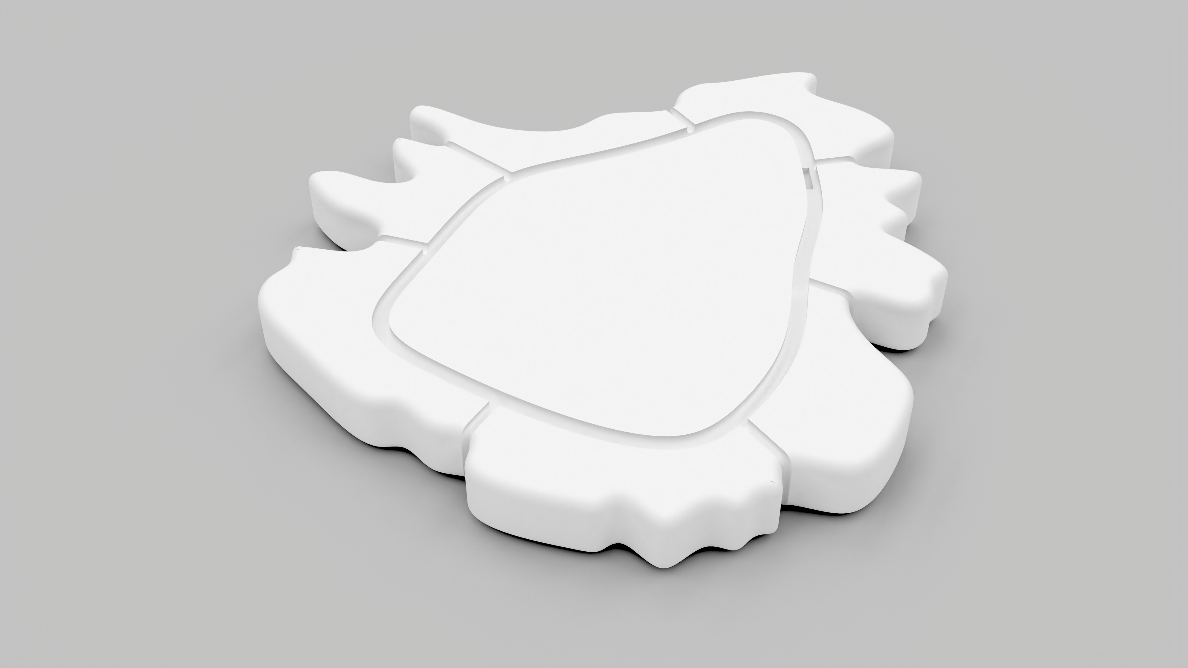
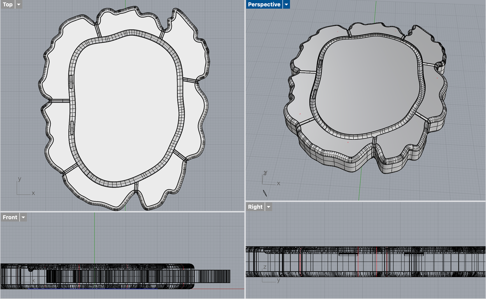
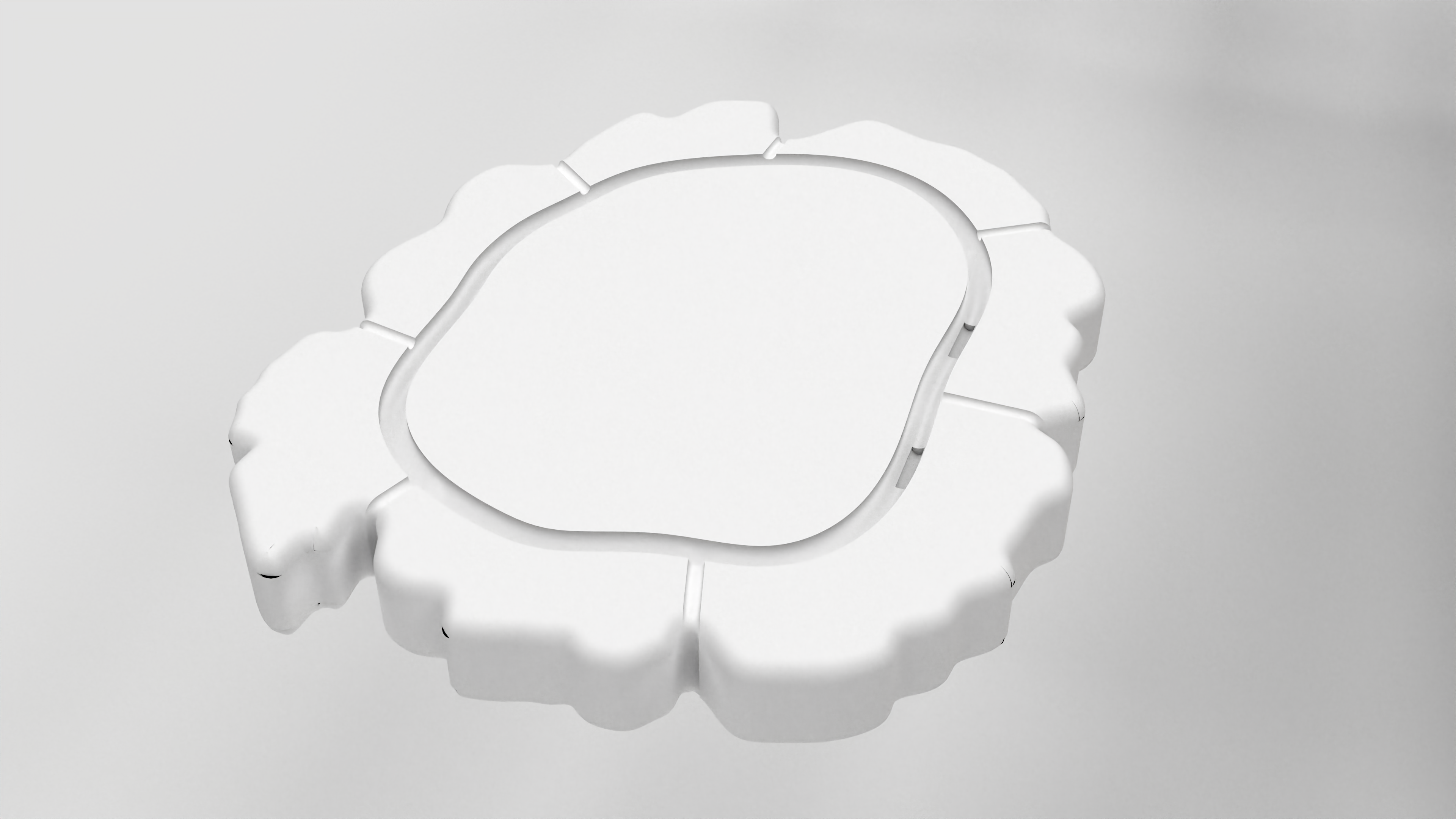
I used the shapes from the bacterial growth to make my final designs, repeating the same steps as I had done previously. This involved tracing the shape of the bacteria in Rhino and extruding to 8mm to make the base shape of my brooch. I then rounded the edges using the fillet tool in order to make it smooth for silicone mould making.
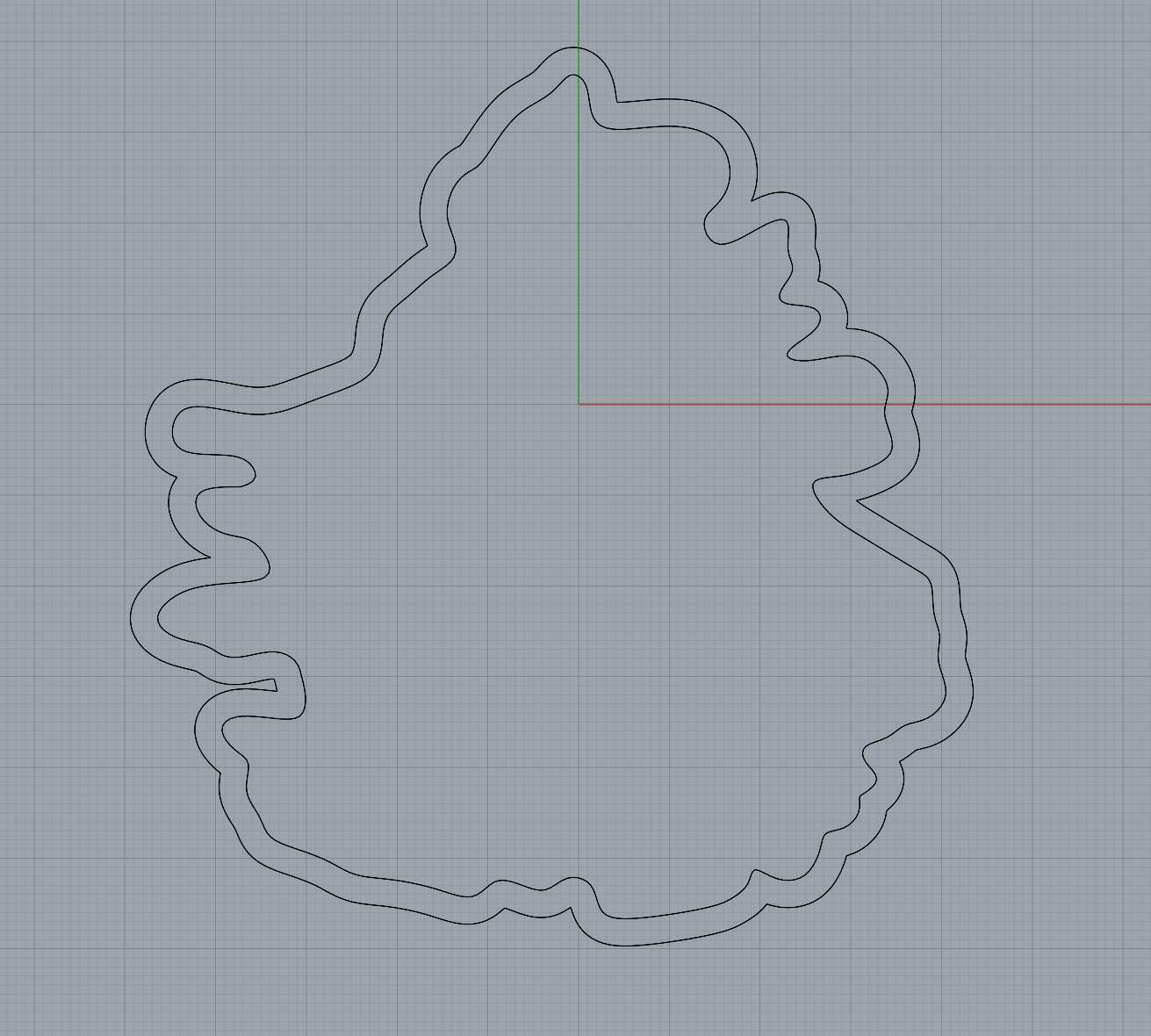
Offset shape for agar
During the final CAD stage, there were lots of tweaks and refinements to my designs. After my formative review, the tutors and I agreed that I should remove the 3D agar front piece, as it was not clear that it was bacteria / agar, and it makes the piece look too busy. Another note was to improve the shape of the agar within the resin. In my first attempt, I had poured the agar into a dish and used the 3D print for the resin as an outline for cutting out the shape. This was not accurate enough and did not look as nearly as refined as I had wanted it to.
While making my final CAD models, I realised that I could take the shape of the moulds I was using for the resin, and simply offset this by 3mm to get the perfect shape for the agar. I then printed this and make silicone moulds for the agar which would perfectly fit in the resin.
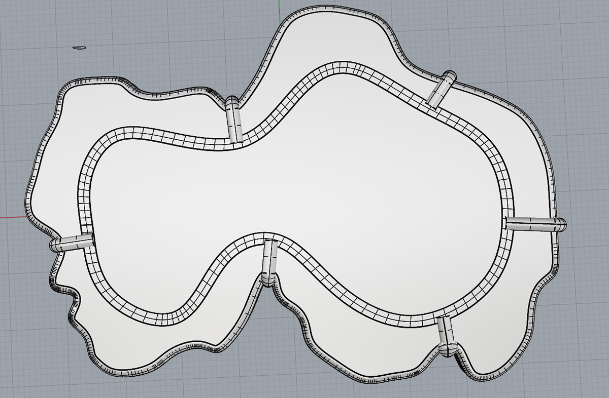
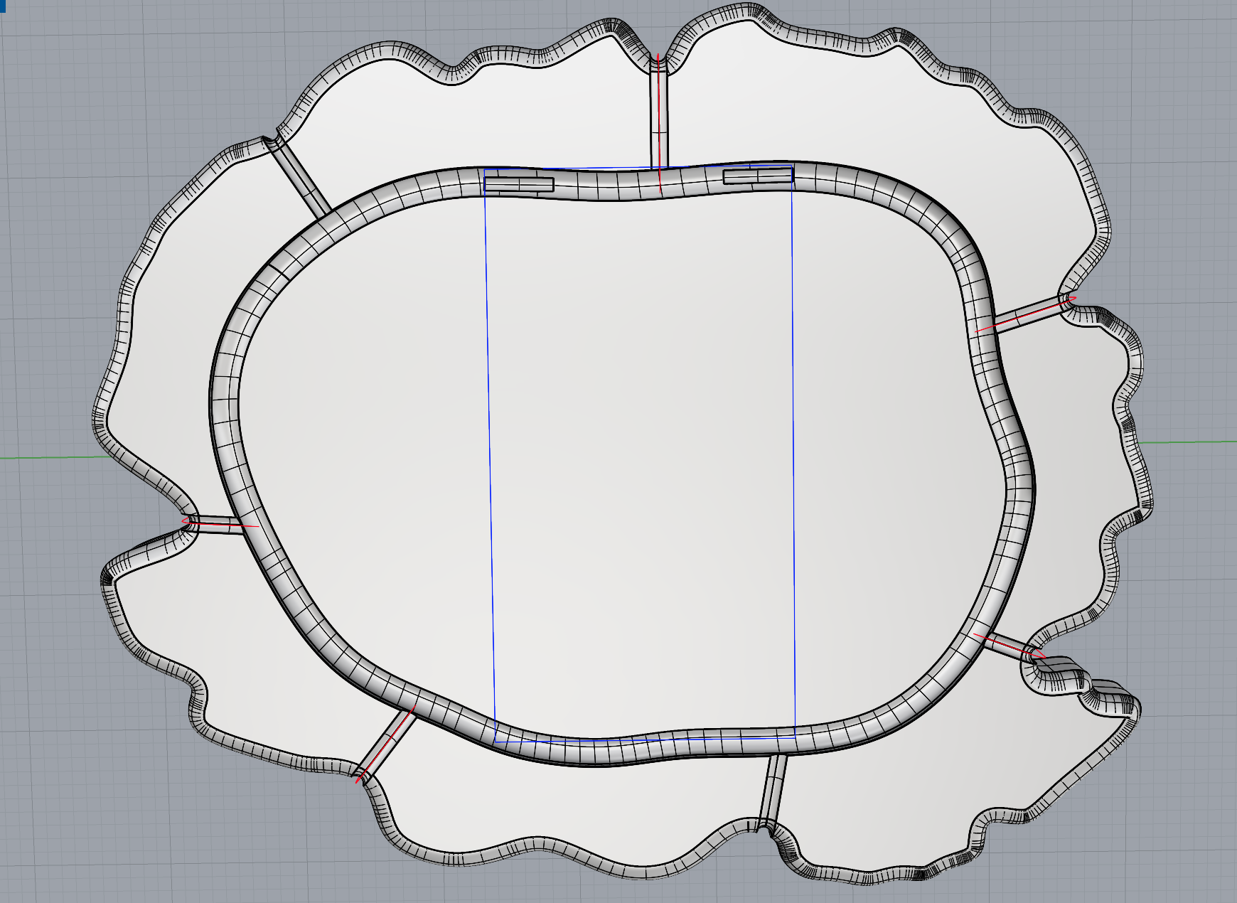
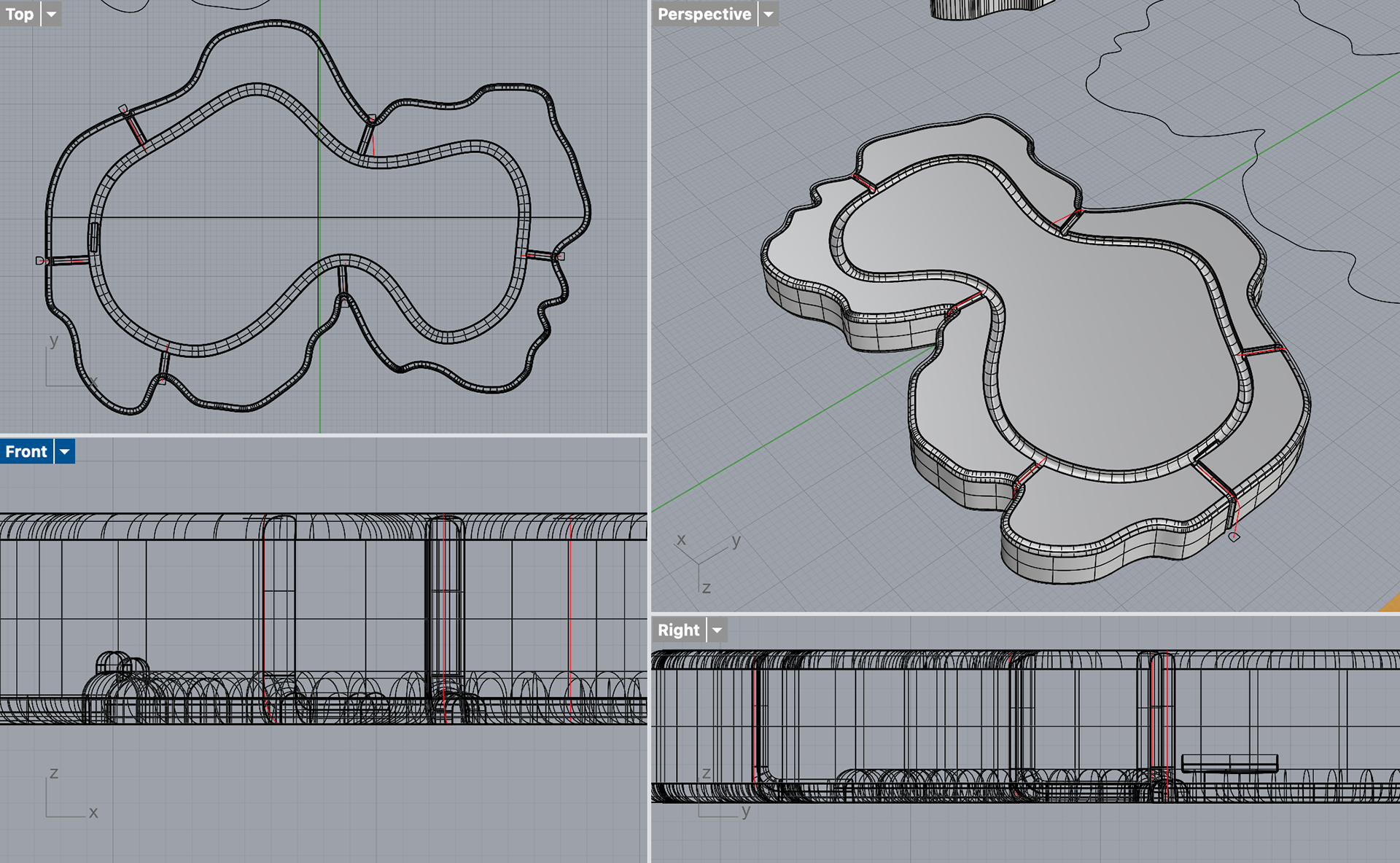
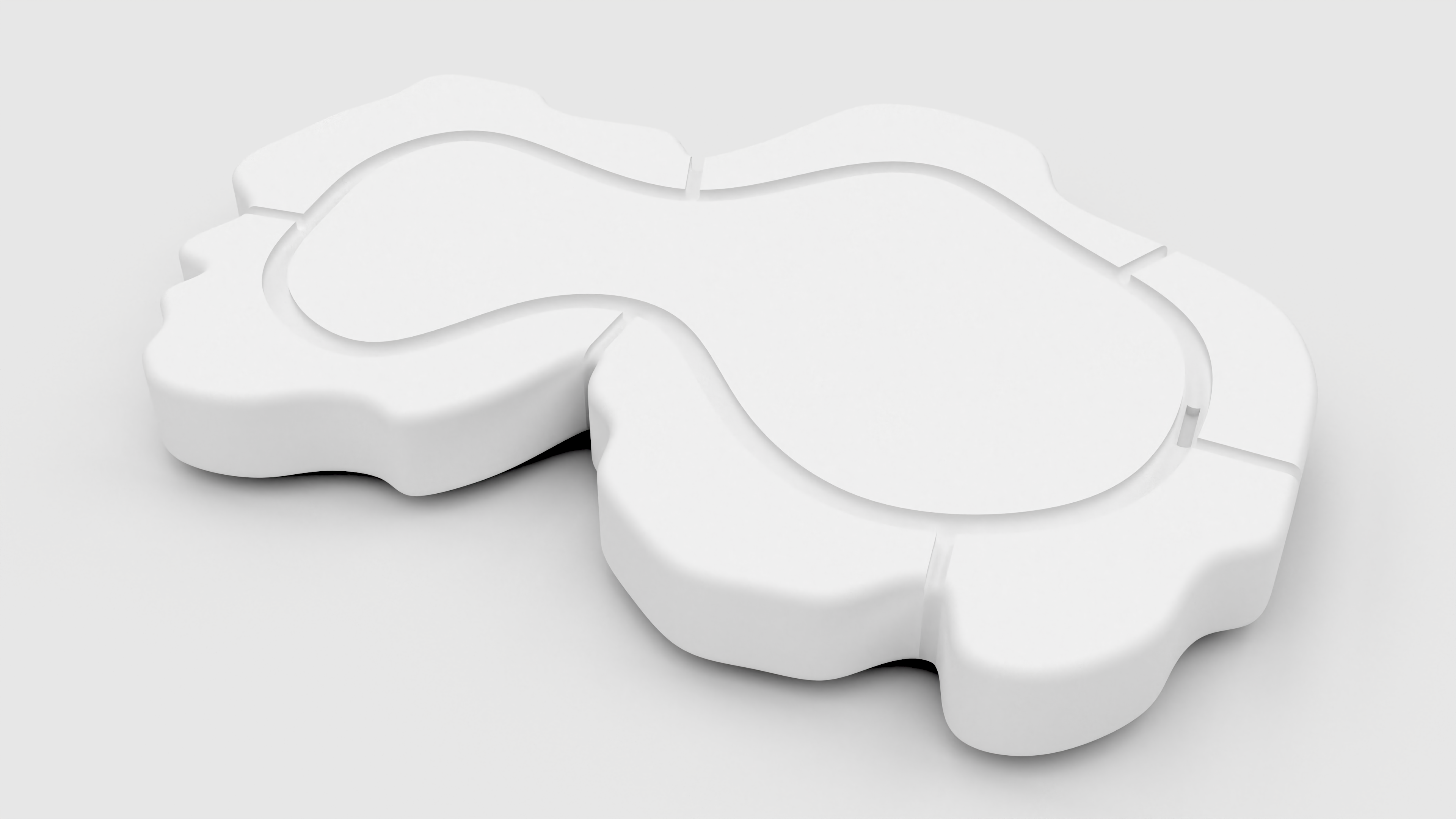
Now that I had the shapes I needed, I could start adding the inset pieces for the silver bezel and the prongs. From my previous samples, I knew that I needed to make the silver bezel relatively simple, as I would not be able to bend the 2mm silver wire as much as the 1mm wire I had previously used. I drew out the shapes using the curve tool and then adjusted them using the individual control points on the line.
Bezel line - pre-adjustment
Original Shape
Print Test
Print Test
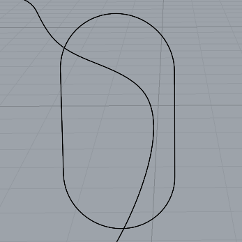
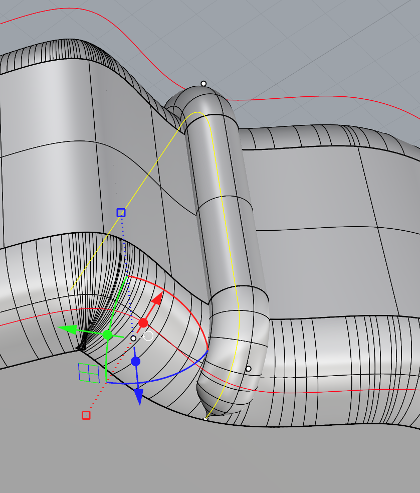
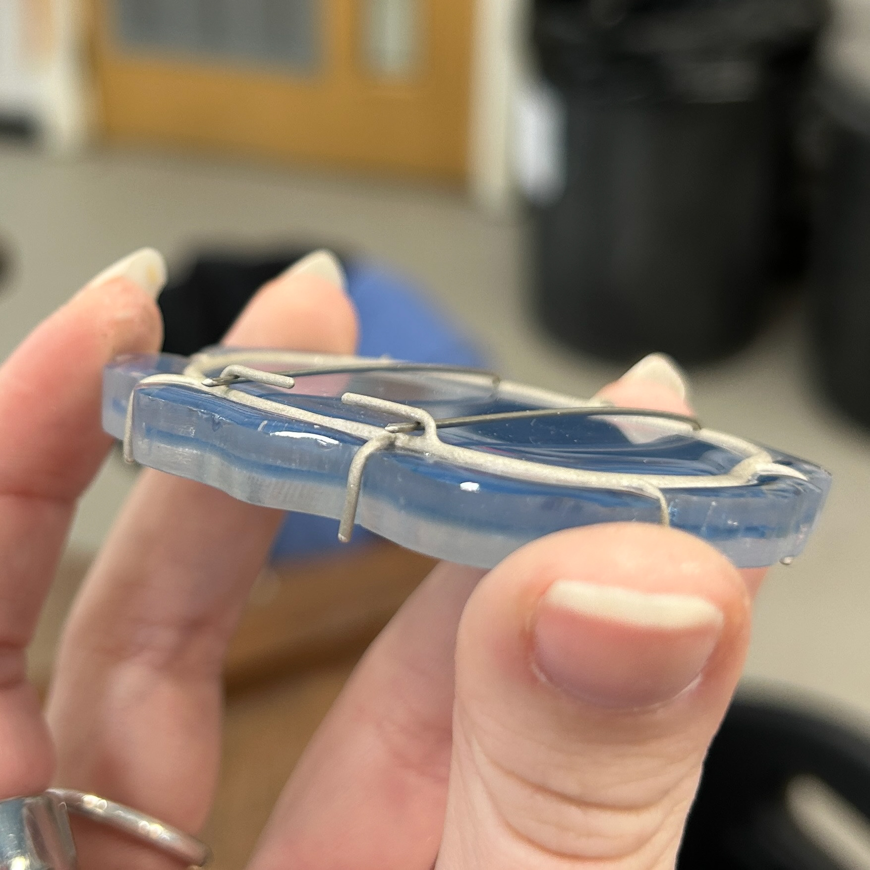
I then moved on to the depth of the bezel. In previous samples, I had just piped this shape and inset the pipe halfway so that the silver would sit halfway into the resin. During my formative review, we spoke about how the silver should be more inset into the design. I knew that I needed to change the shape of the pipe to somehow make it deeper.
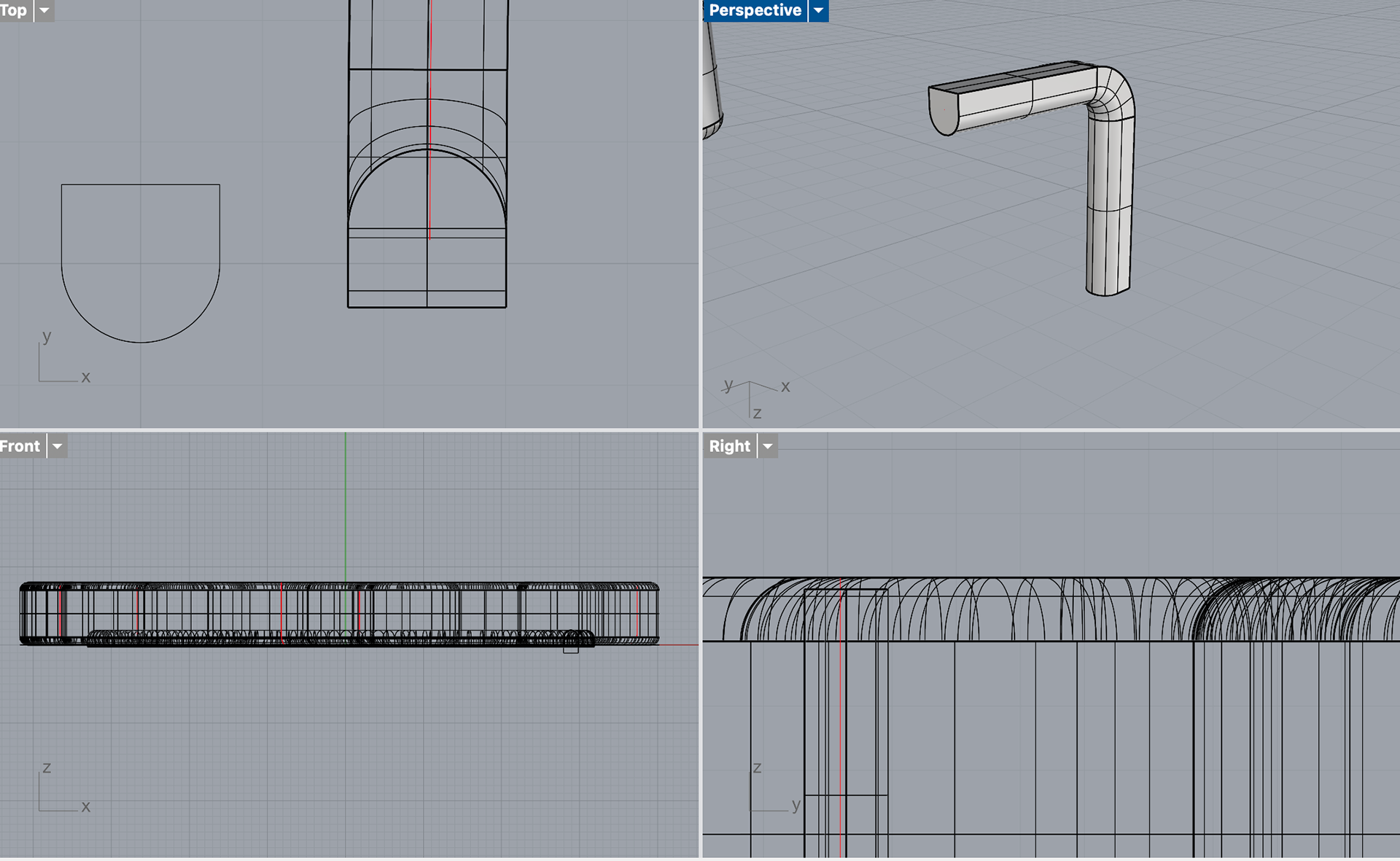
I first tried this by stacking two circles on top of each other, connecting them with two lines and trimming the excess. However, I found after printing that this was much too deep, and now there was much too big of a gap between the top of the resin and the start of the silver. I found that a circle with a flattened top was the perfect shape. The flat top allowed the shape to be recessed into the mould while still being able to use the Booleon difference command. The video below shows me using the sweep1 tool instead of the pipe tool to create this shape.
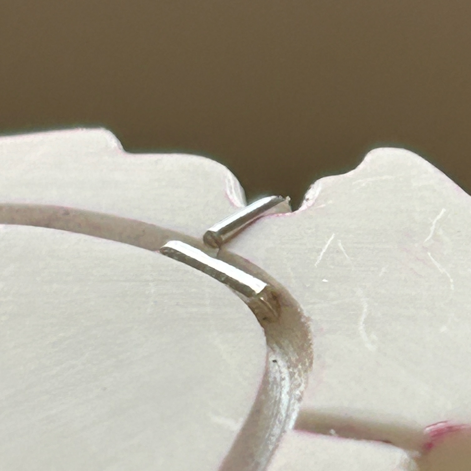
Now that I had the shape for the bezel, I could move on to recessing the prongs. I first tried to create a prong that slightly tapered at the top so that the silver would seamlessly wrap around the sides of the resin and onto the top. However, this caused many problems. Not only was it hard to pipe the shape accurately, but it also caused many problems when trying to booleon the shape. I showed Geoff the problems in Rhino, and he suggested that I just pipe the shape as normal and then sand a taper into the shape after printing as this difference in CAD was so minor.
I first printing these prongs using the same method as I had done for the initial bezel, recessing the prong halfway into the model. However, after printing, I decided to go back and use the same method as I had done for the bezel.
I also decided to change the thickness of the space for both the bezel and the prongs from 2.3mm / 1.2mm to 2.2mm / 1.3mm, as these fit better with the 2mm and 1mm silver wire I was using. I first tested this by printing a small part of my design before committing to printing the whole thing.
Attempting to create a tapered edge
Half insetting the prongs
Final prong design
2.3mm / 1.2mm with the half inset prong design
2.2mm / 1.3mm with the final inset design
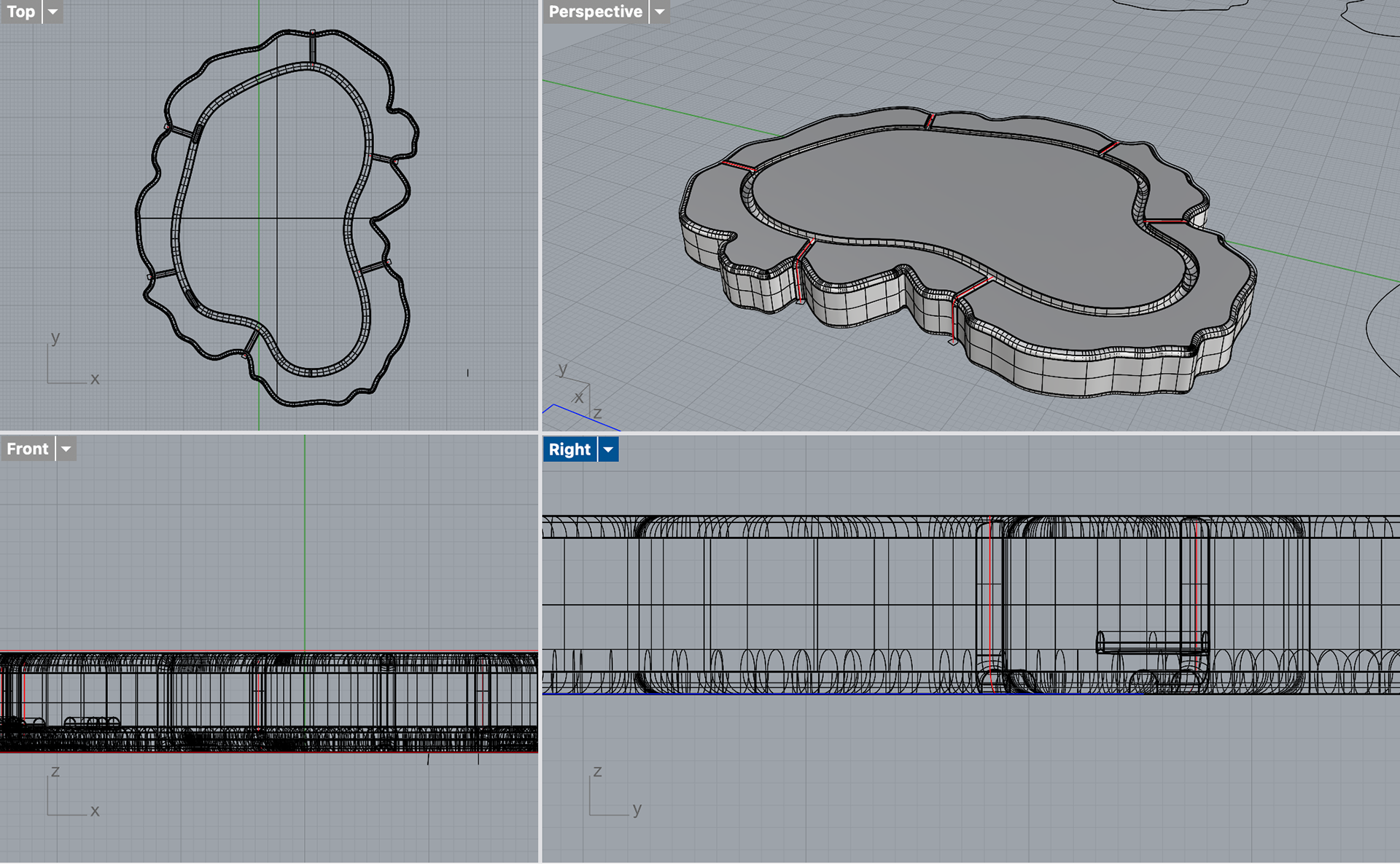
When adding the components for the brooch mechanism, I decided to use lines to make sure that the pins would be parallel. I knew that it would be impossible to have a perfectly square brooch because of the bezel shape I was using; however, after speaking to Patricia, she told me that as long as the bottom pins were even, then the top part of the brooch didn't necessarily have to be even.
Now that I had all of the correct components for the designs, I could refine my CAD models and print these ready for sanding and silicone.
Final Designs
Day 1
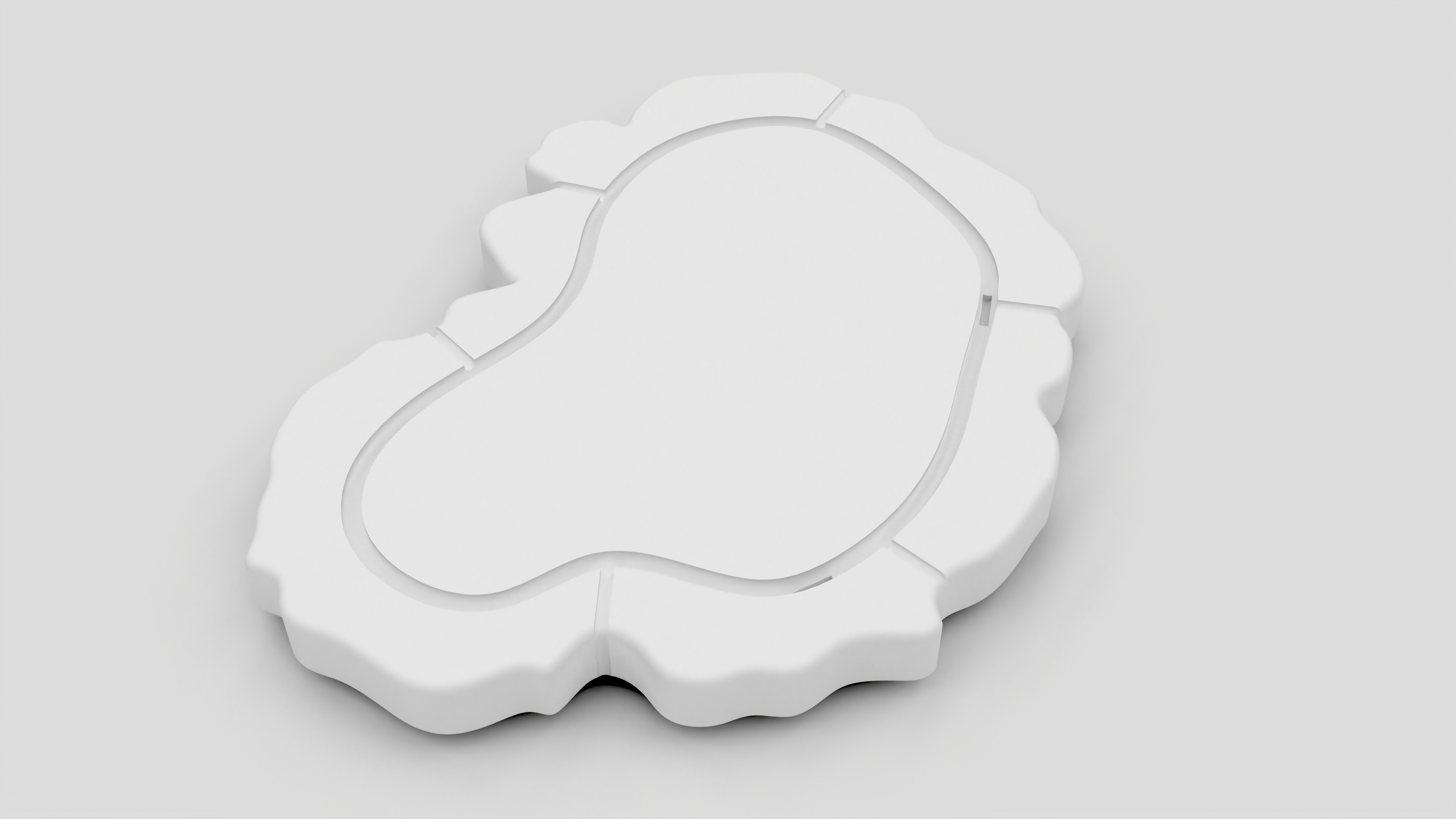
Rhino Render
Day 2
Rhino Render
Day 3
Rhino Render
Day 4
Rhino Render
Day 5
Rhino Render
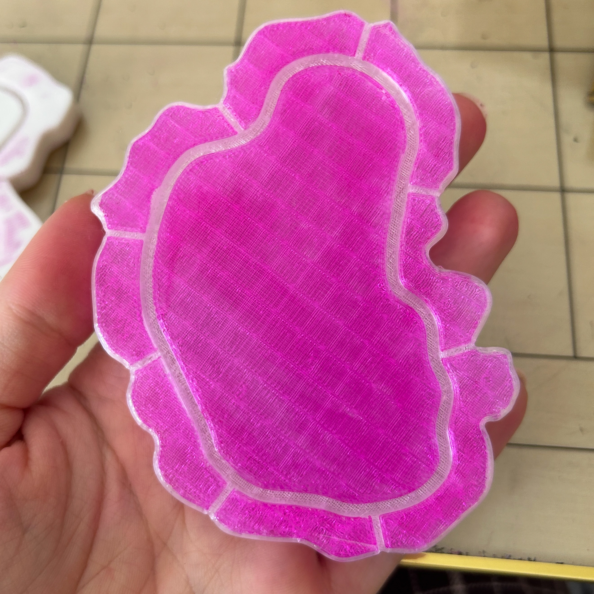
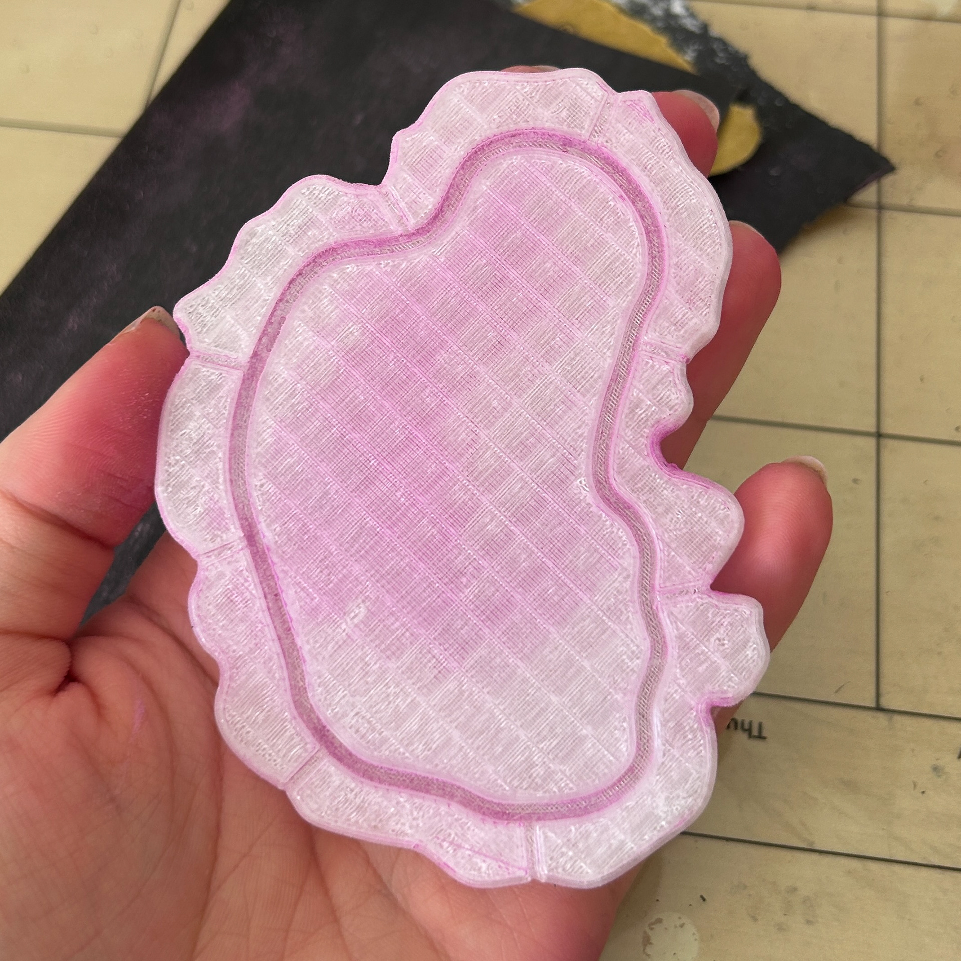
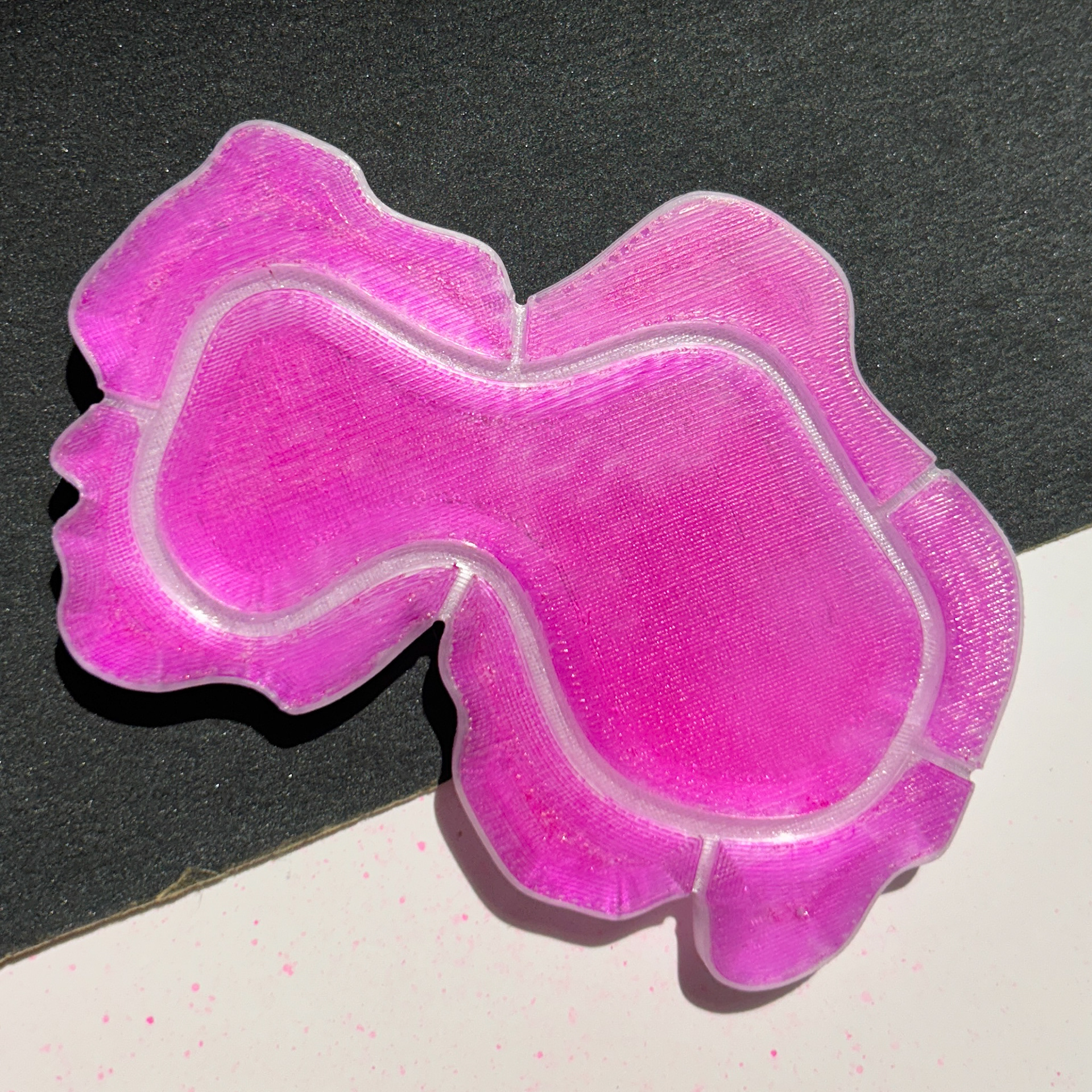
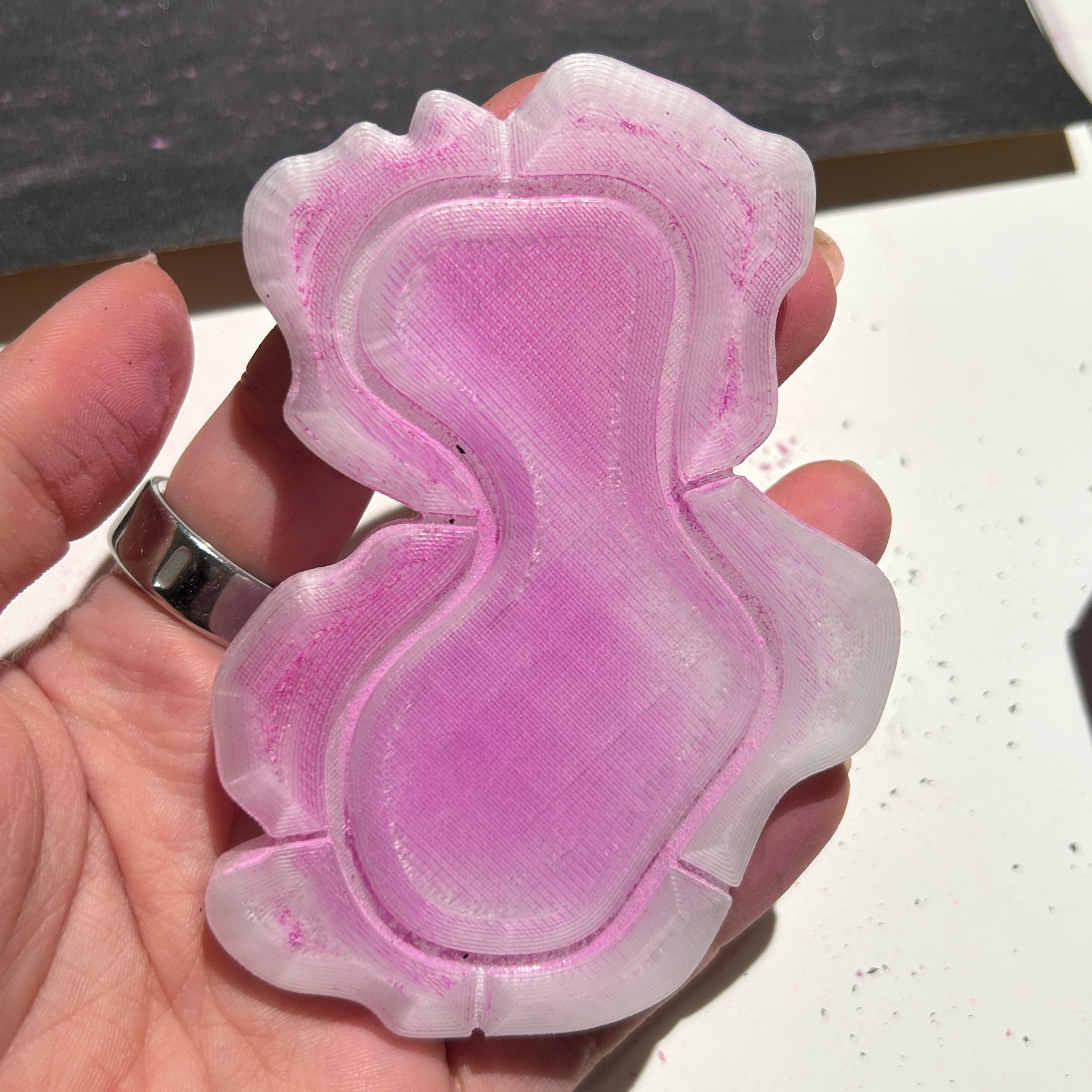
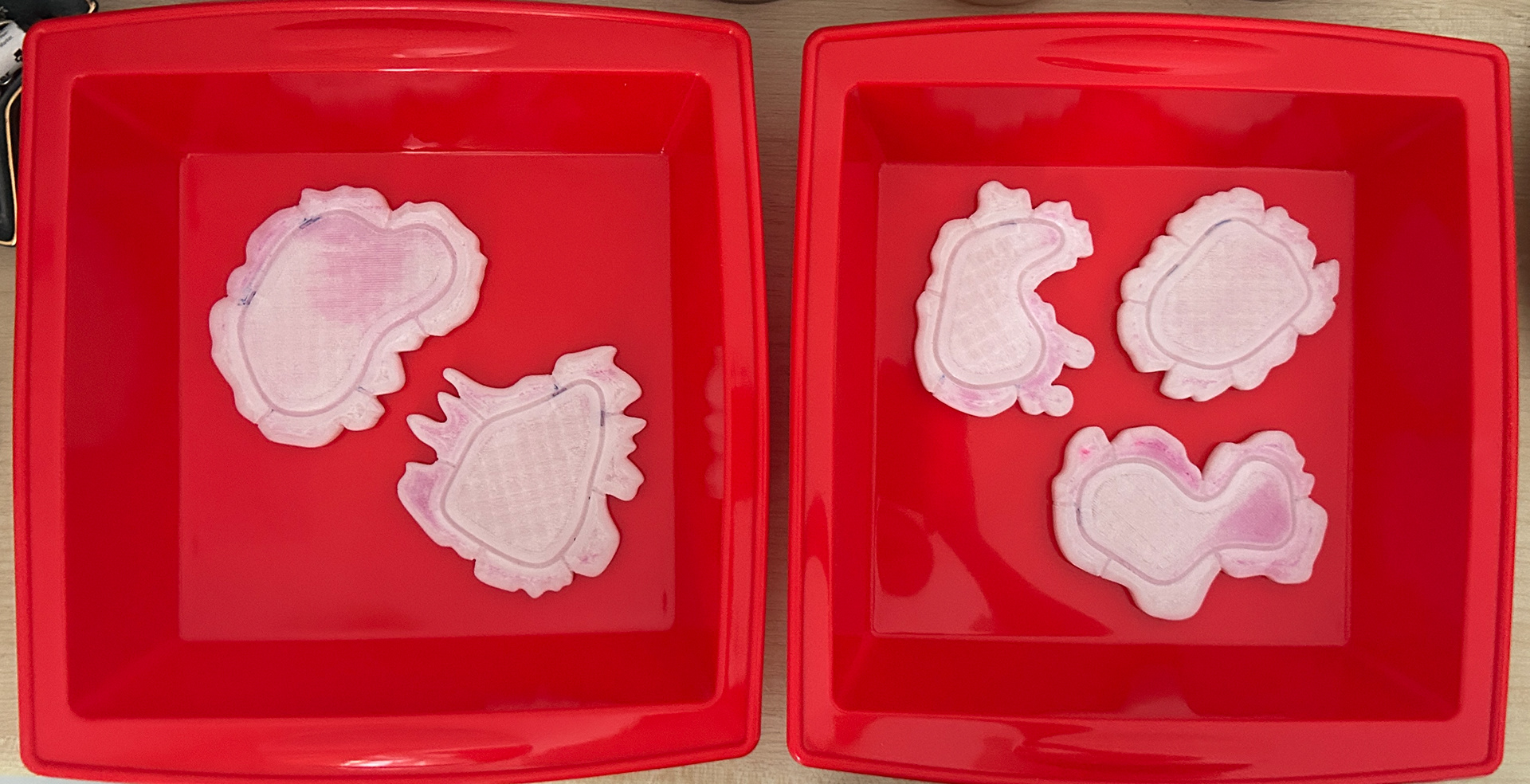
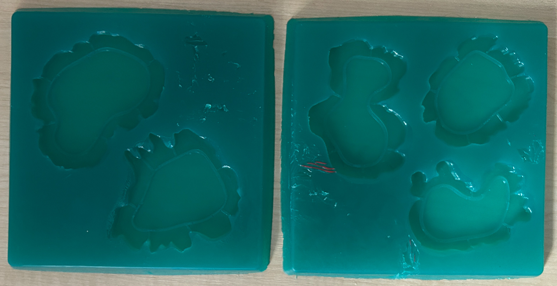
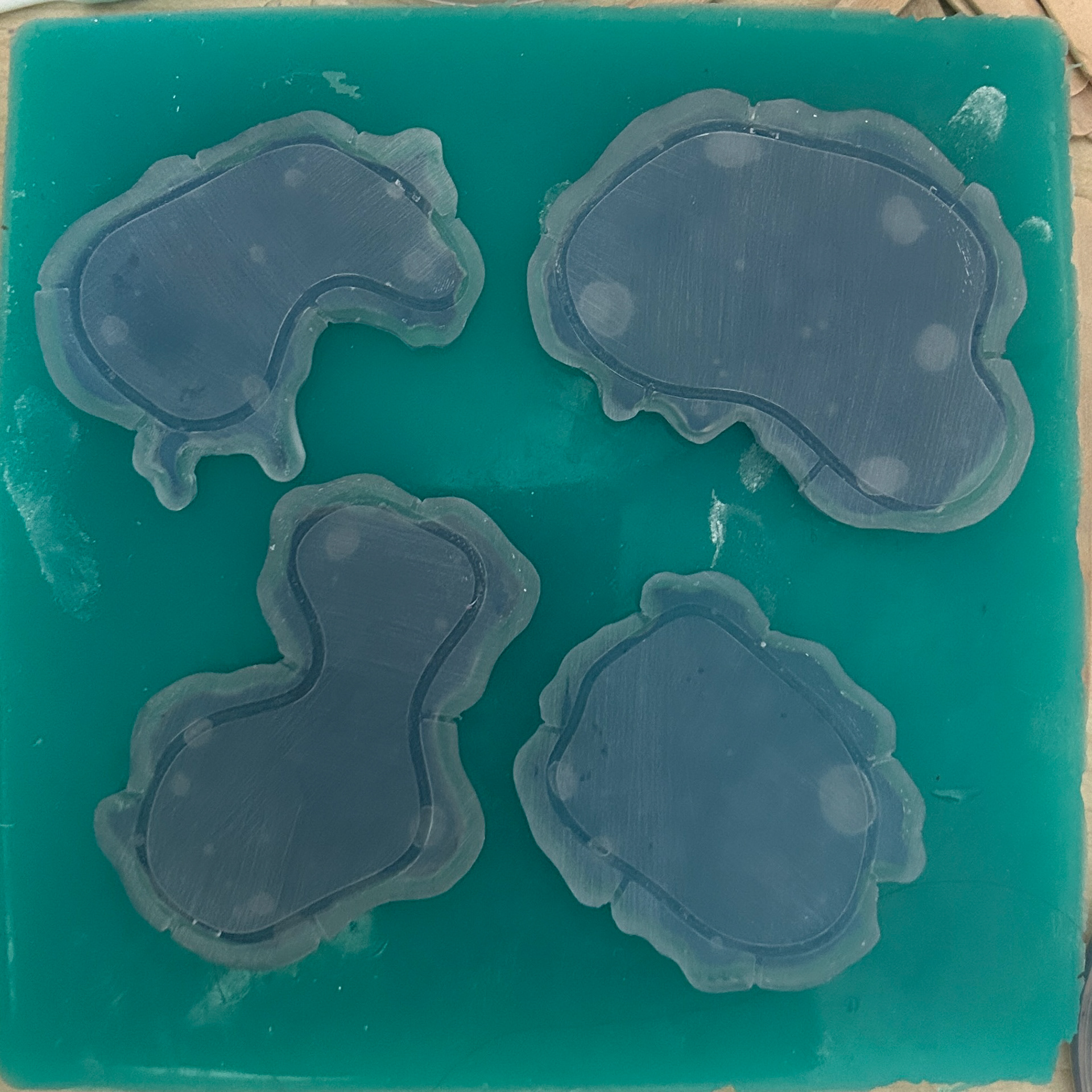
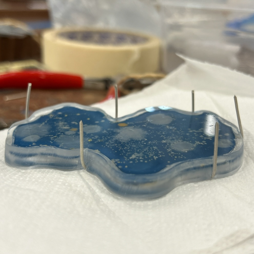
Agar Moulds
Gluing the prints to the silicone
Pouring the silicone
Agar ready to be transferred into fridge
Agar in dishes ready to be inoculated
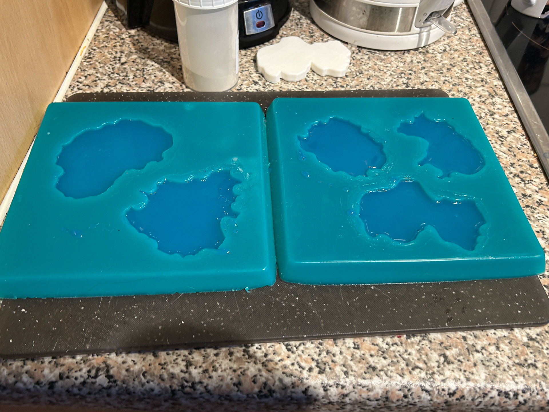
To make the moulds for the agar, I used the same steps as I had previously done. I bought new silicone moulds that were larger, which allowed me to fit multiple prints into one mould. I glued the prints to the silicone and then poured my silicone over these.
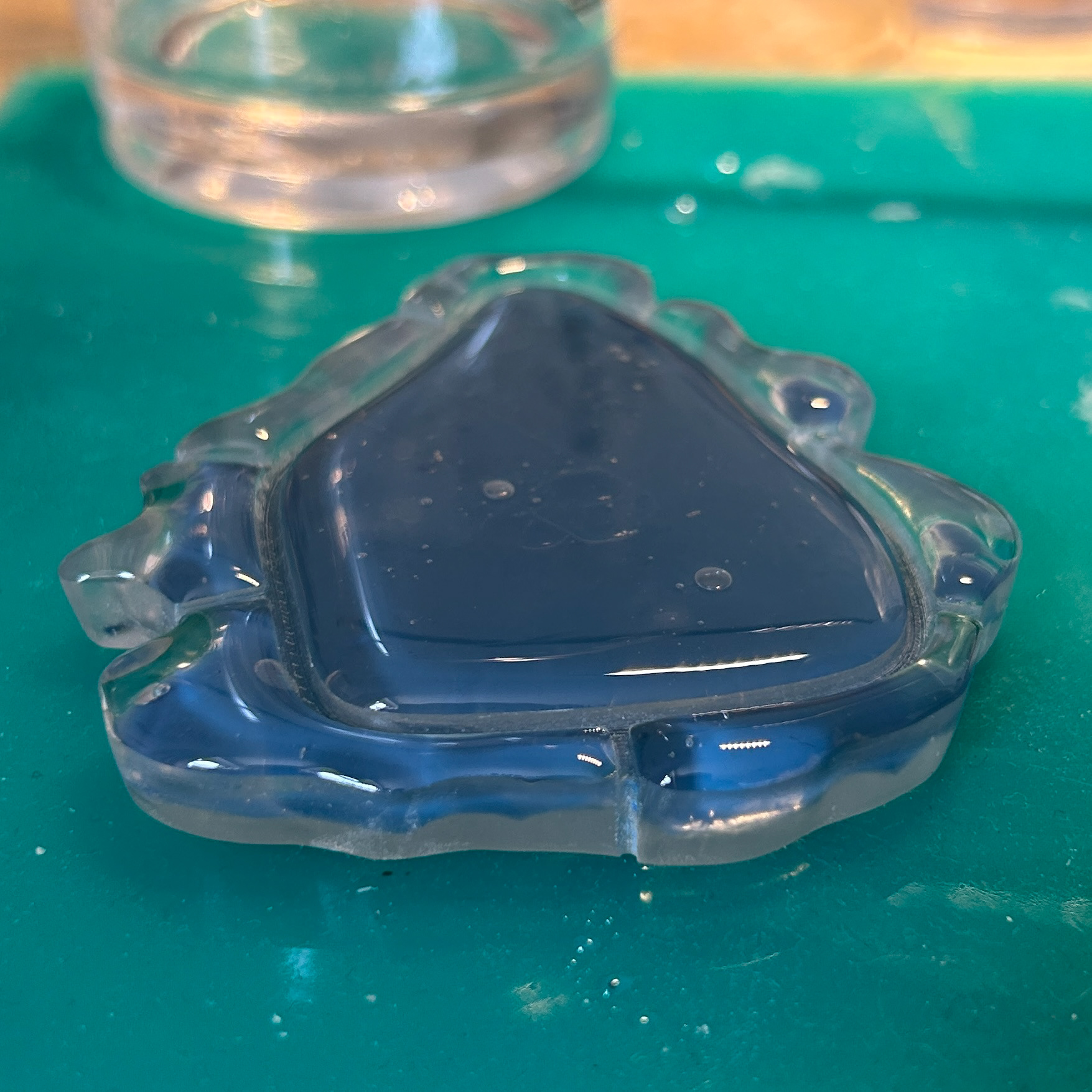
After 24 hours, the moulds were ready to be used. I decided to use the same method as I had done in Unit X whereby I grew three samples for each day as this gave me backups in case there were any issues with both the growth of the bacteria and/or the movement of the agar within the resin. While I knew that I would only be able to fit two samples of each shape in the cupboard at one time, this meant I had backups in case the agar was too thick or thin, and if it broke for any reason while transferring to the resin.
Making triple the batch of agar also meant that I had to be quick when pouring and setting the agar, as the agar in the pot would eventually start to create a film on the top layer if it cooled down too much. I have previously tried keeping the agar solution on a simmer to help prevent this, however, I have found that too much water evaporates and therefore makes the agar solution too thick.
To help keep the time the agar was on the stove down, I decided to place the moulds with agar in the fridge, as it would set in approximately 3-5 minutes.
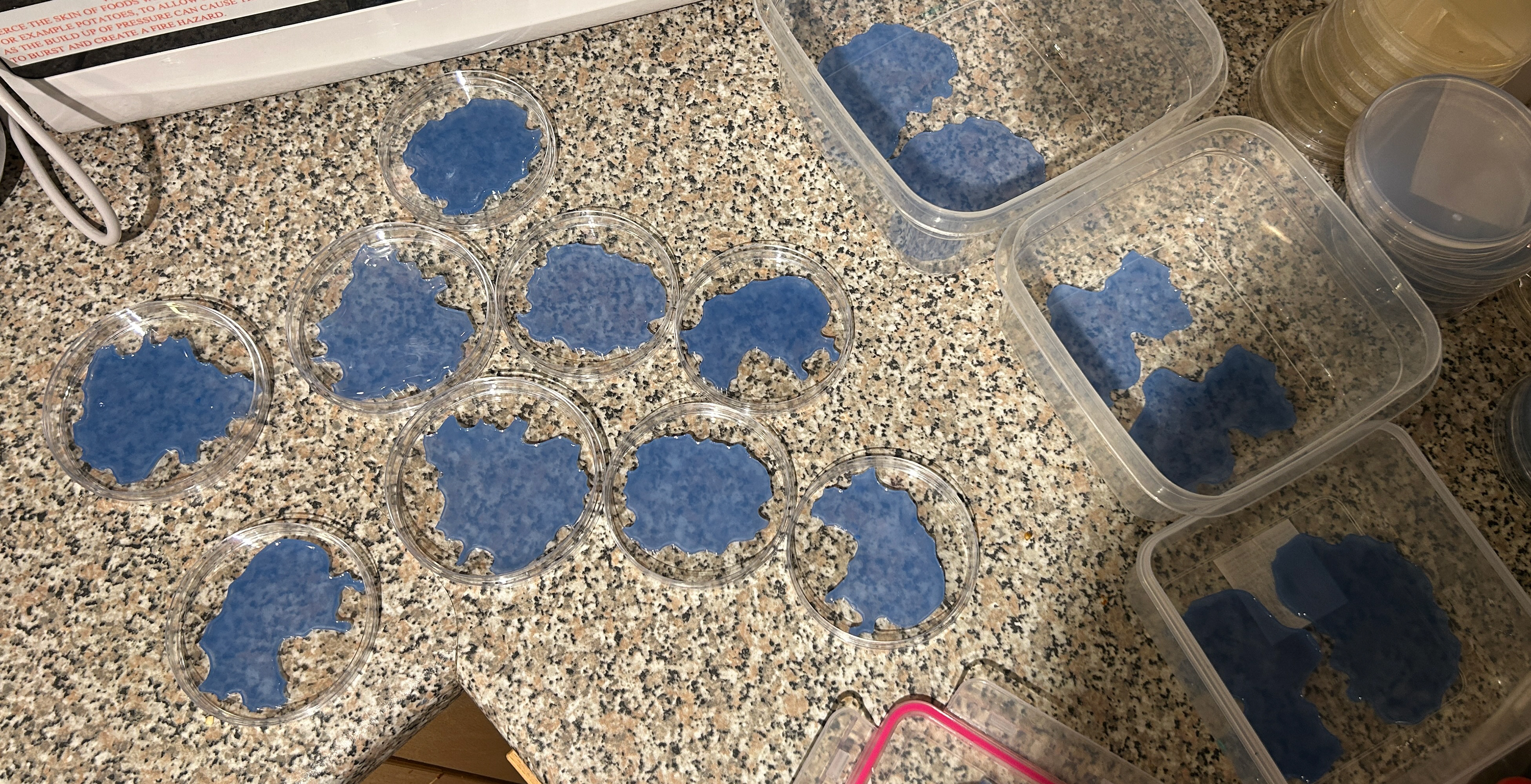
Once all of the agar was made, I transferred each of them into dishes ready to be swabbed.
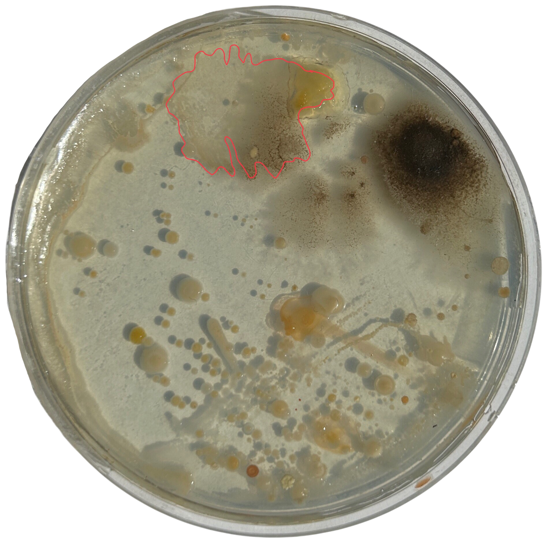
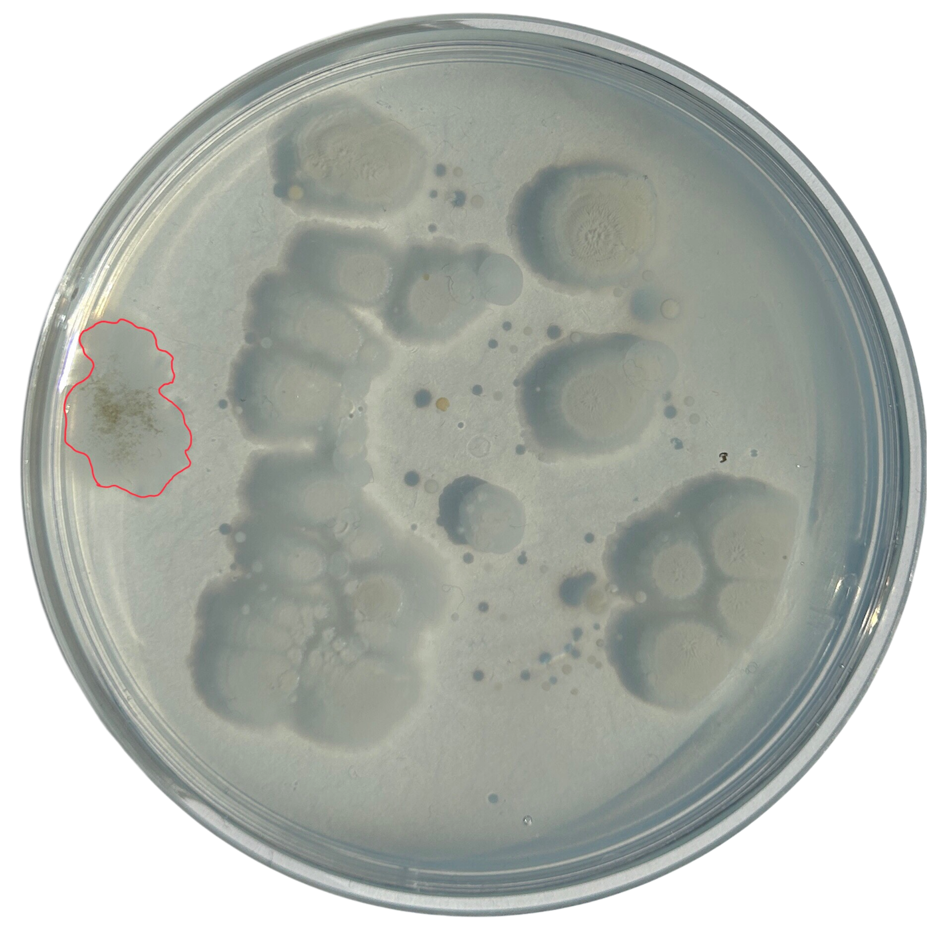
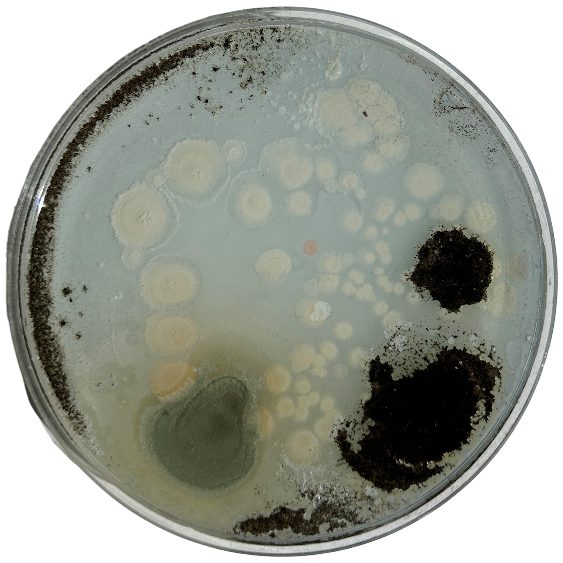
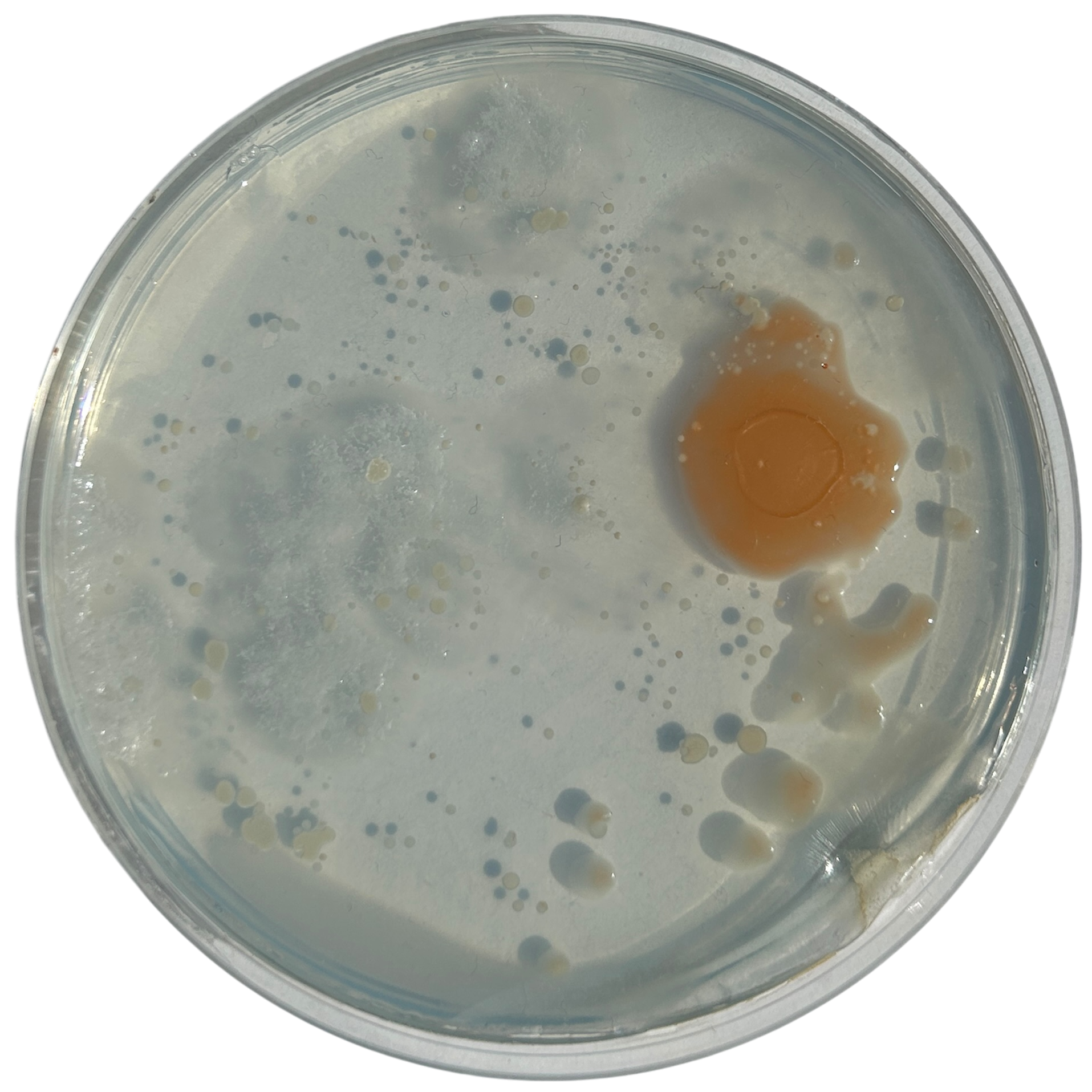
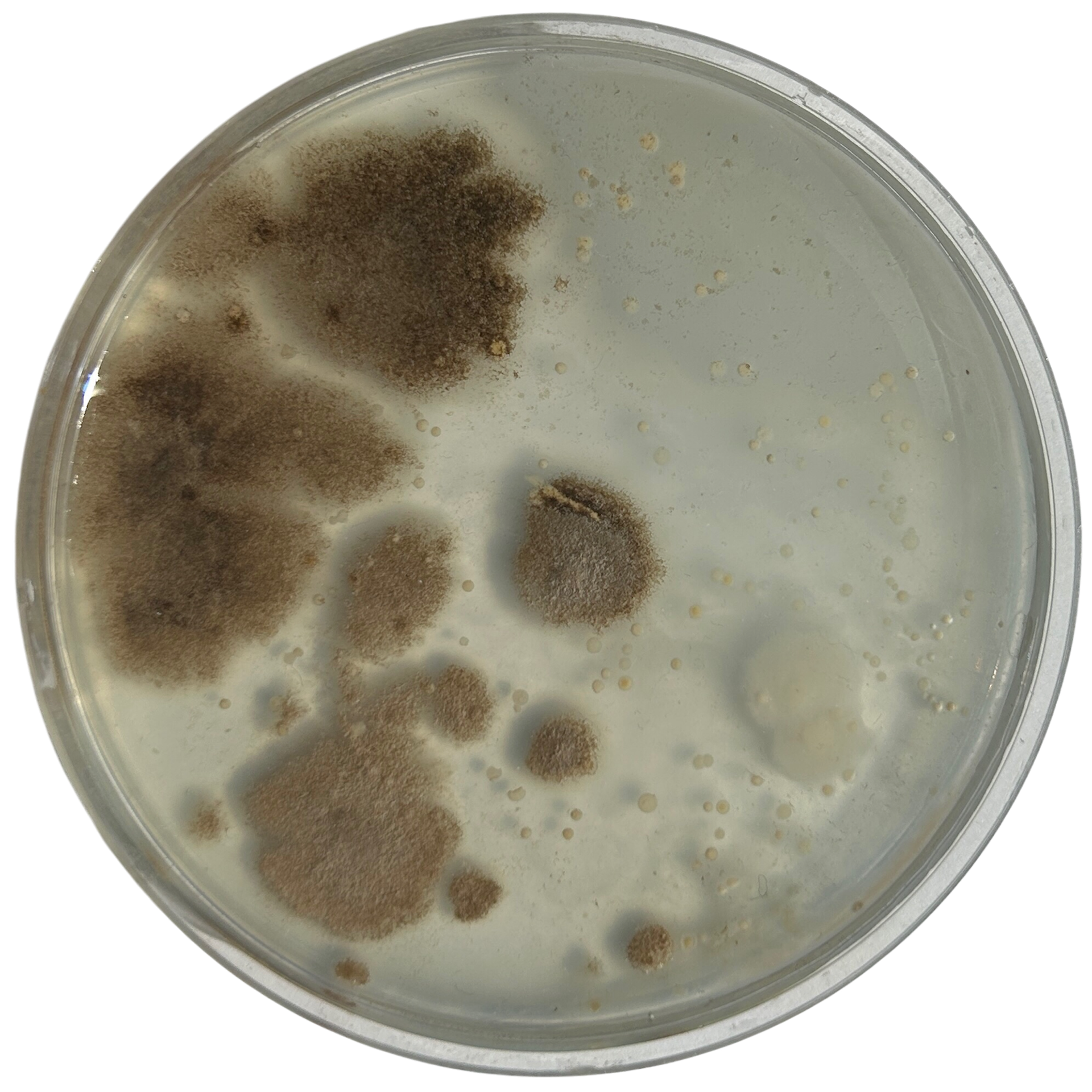
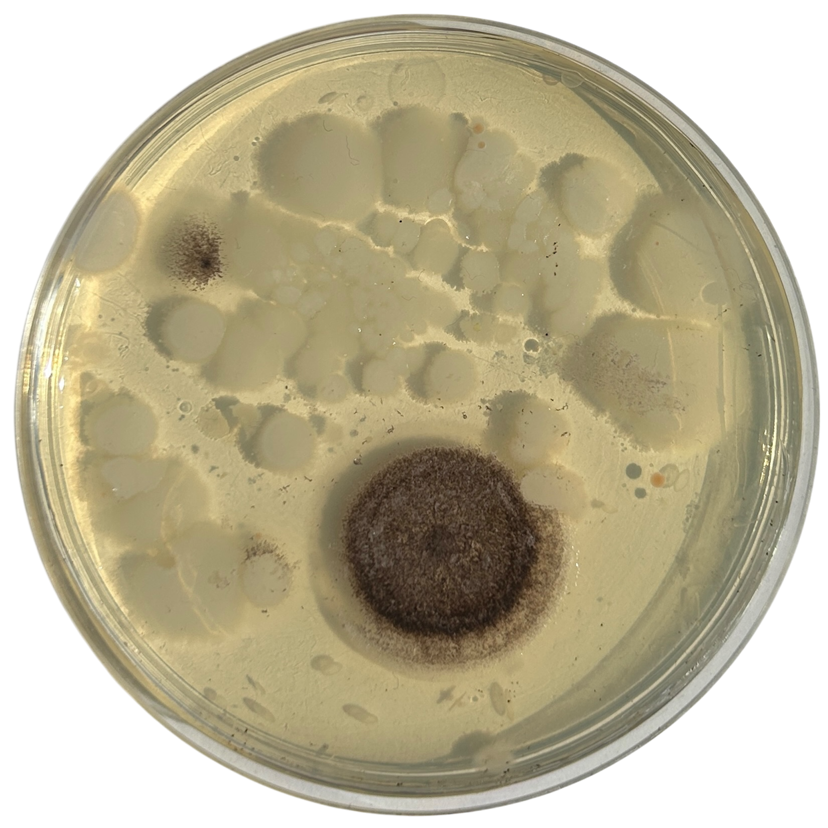
Weirdly enough, the swabs I did resulted in black fuzzy growths all over the pieces. I think that this was because of the placement in the cupboard, and these were further towards the back, where the heat is stronger. I believe that in the hot weather, the cupboard may have gotten too hot at the back, resulting in some overgrowth of bacteria. On traditional nutrient agar, I have had this happen, but the growths have been green; however, with Potato Dextrose Agar, the growths are clearly black.
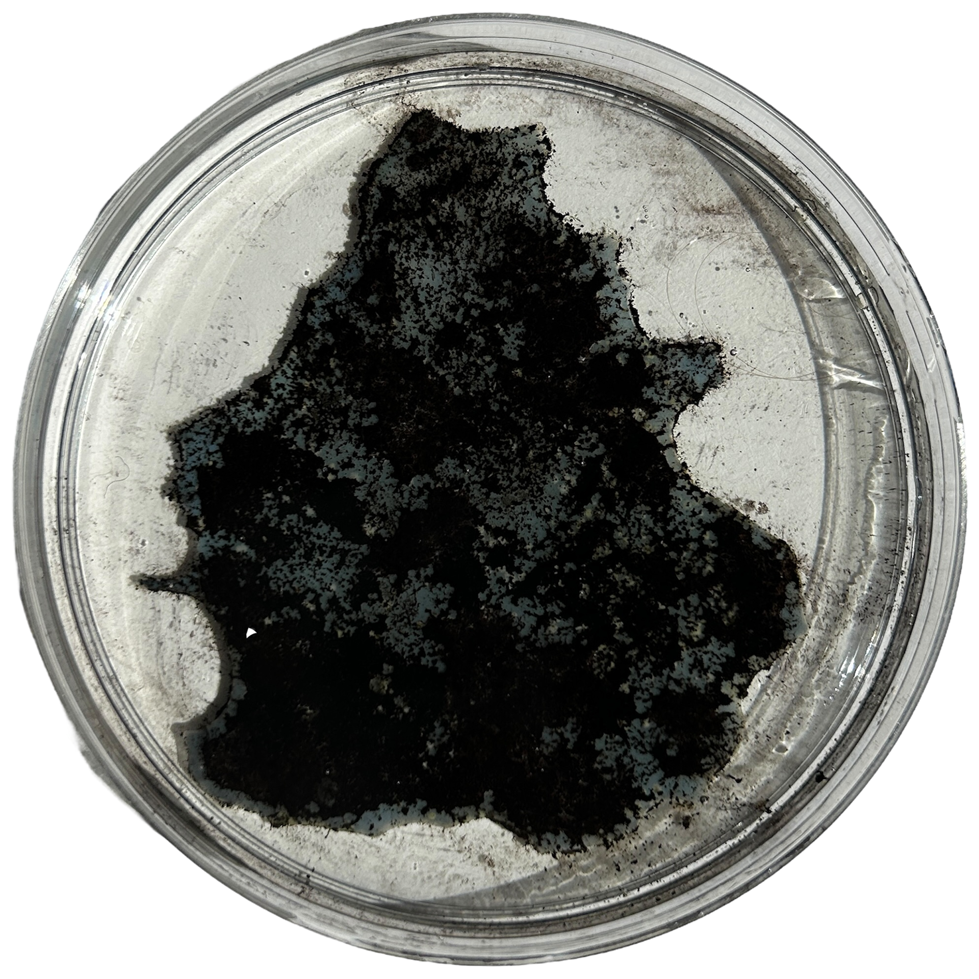
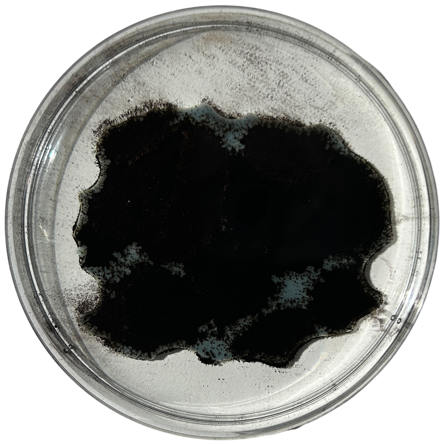
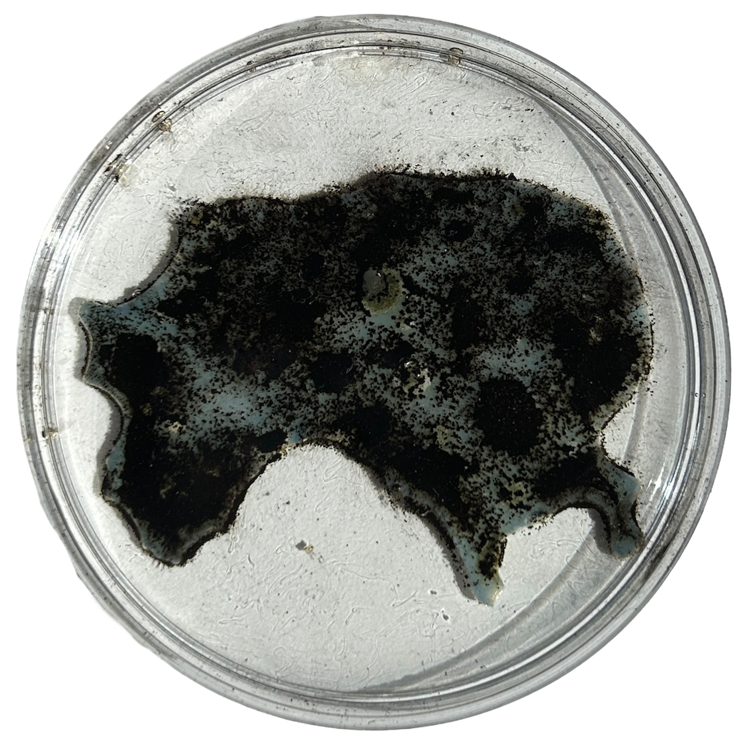
Unfortunately, I also found that I had grown this particular sample day the wrong way round. I still had a spare set of dishes in the fridge as my contingency, which was the same colour as the other samples, and so I had one more attempt at getting the samples correct.
I decided to swab the samples and culture them over another 5 days, and hope that the agar did not get too hot in the cupboard. I could have simply swabbed that piece again, however, that would not align with my narrative, and so another 5 days of growth was needed.
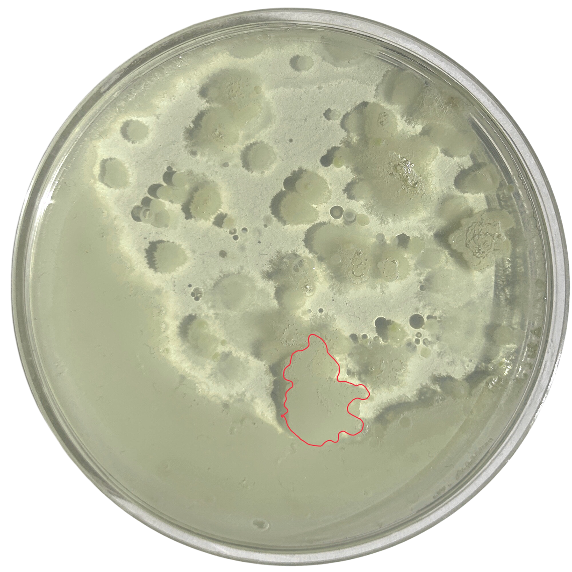
Examples of the Bacteria from that Week of Growth
Sanding Prints
PLA
PLA
PETG
PETG
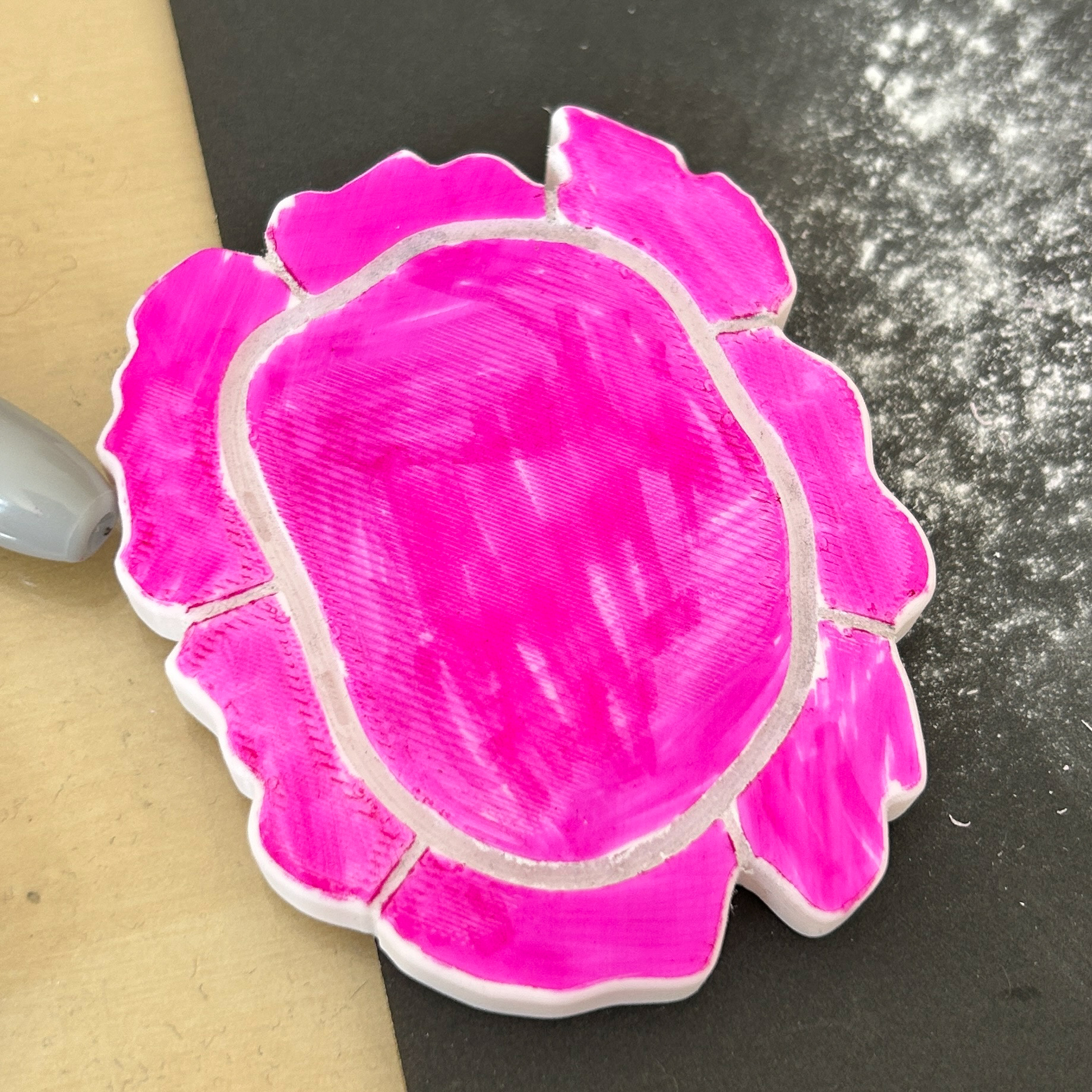
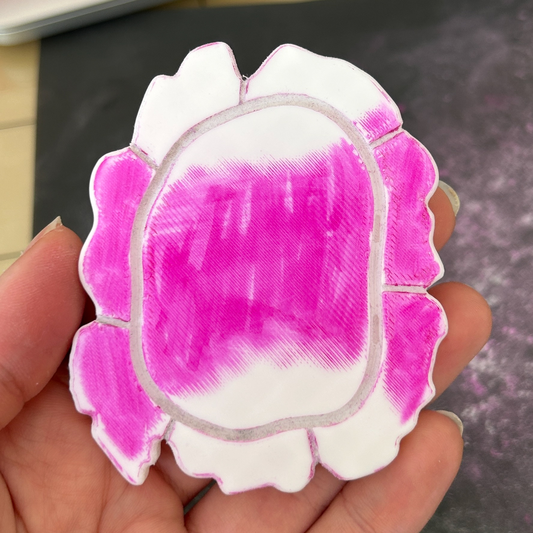
Now that I had all of my prints done, I needed to sand them in preparation for the silicone. I had originally printed these in white PLA so I could use the same sharpie method as I had done in Unit X. However, I found that the sanding was taking far too long. I researched whether there was any way to make sanding 3D printed parts any easier than the figure 8 method I was using. Interestingly enough, many people online had said that PETG was a much easier material to sand. It was not clear why, however, I wonder if it may be because it has a higher printing temperature, therefore making it less likely to clog up the sandpaper.
I therefore printed one of my samples in PETG to test this theory and found it much easier to sand. The only PETG filament I had access to was transparent, which did make it slightly harder to see where I had sanded, even with the Sharpie.
PETG
PETG
PETG
I printed these pieces with 8 walls instead of the standard 2 to give myself contingency when refining the prongs using a small Dremel tool. To make the prints suitable for use with silicone, I sanded them by hand using grits ranging from 600 to 3000. Although this process was time-consuming, previous attempts to speed it up with lower grits left deep scratches on the surface, which was something I wanted to avoid.
Silver
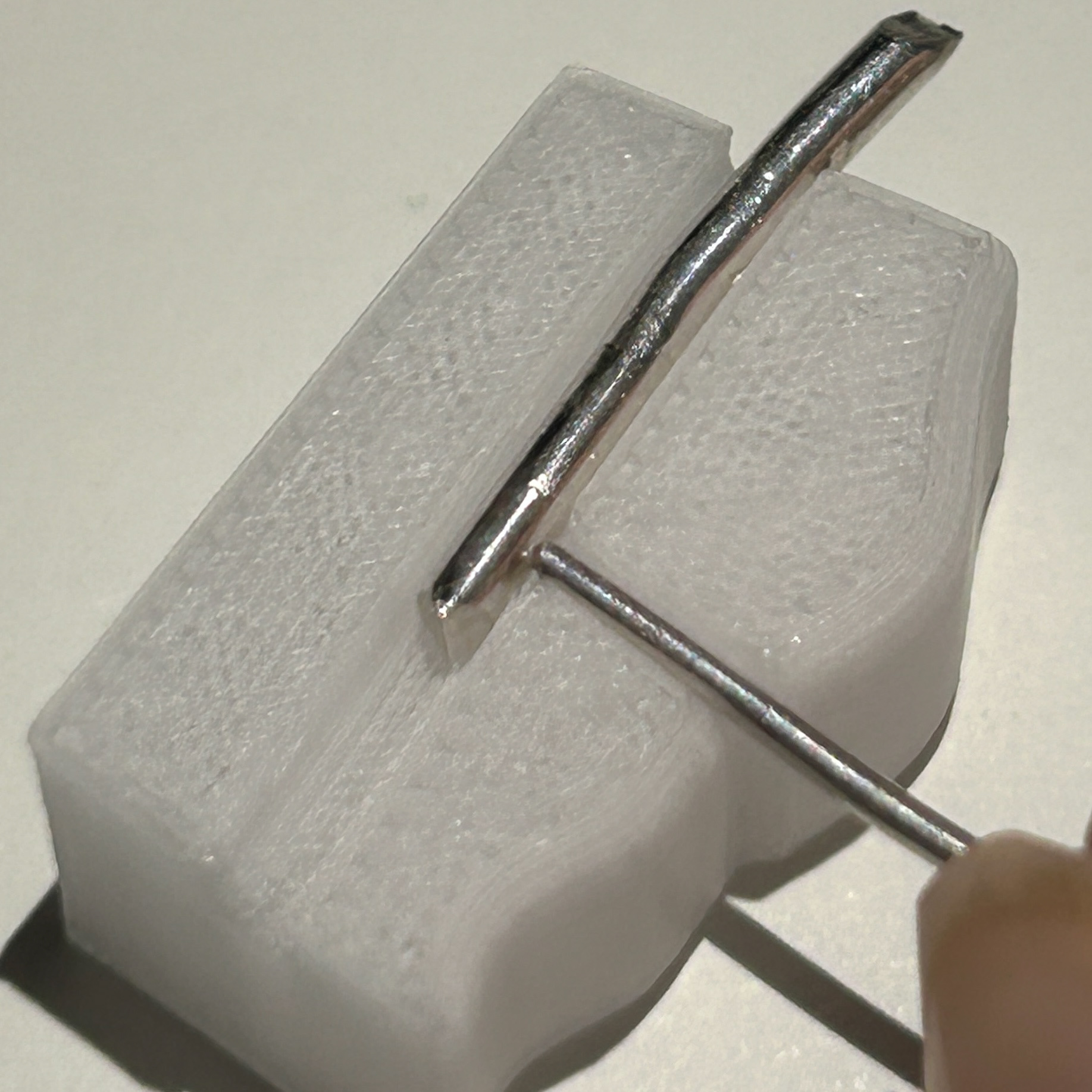
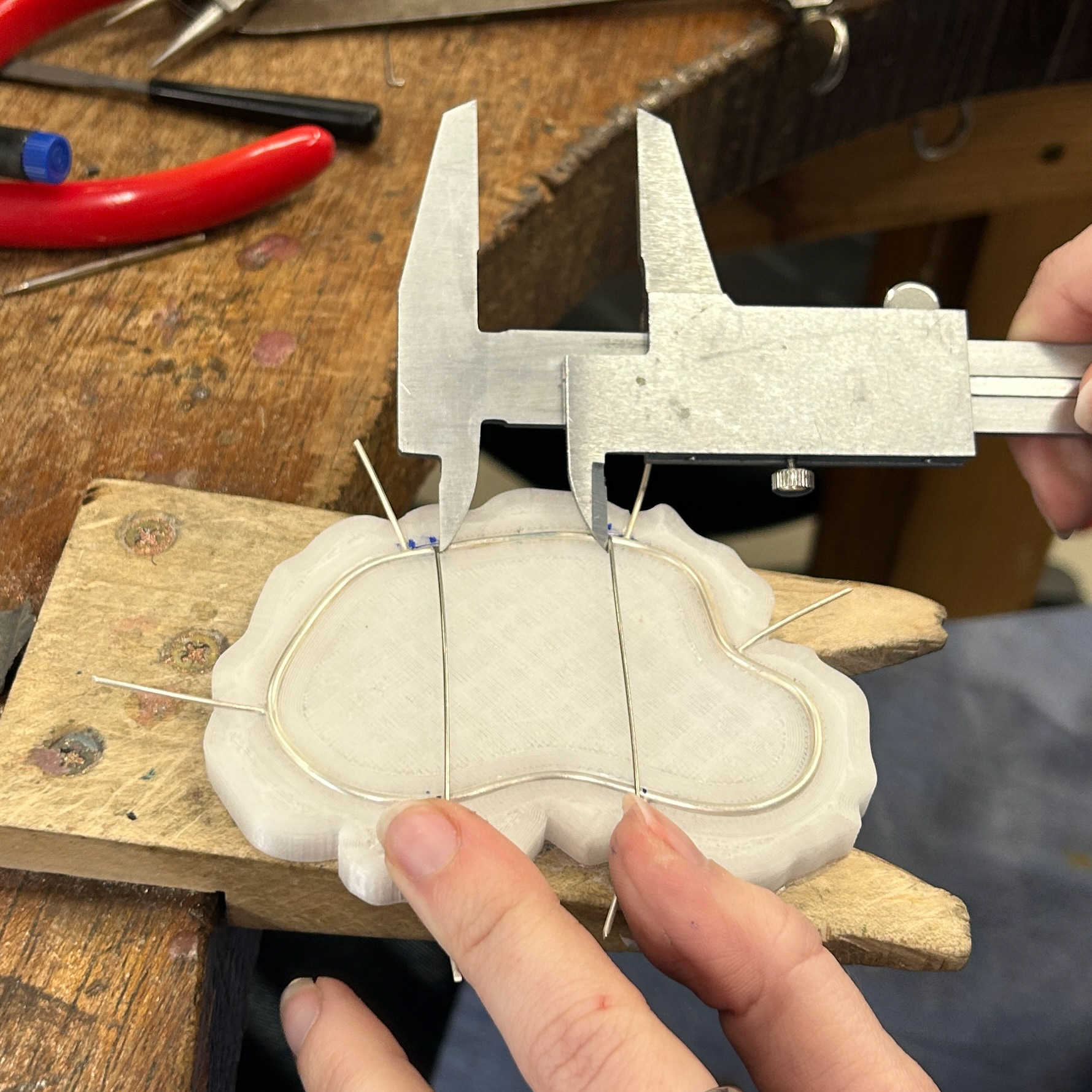
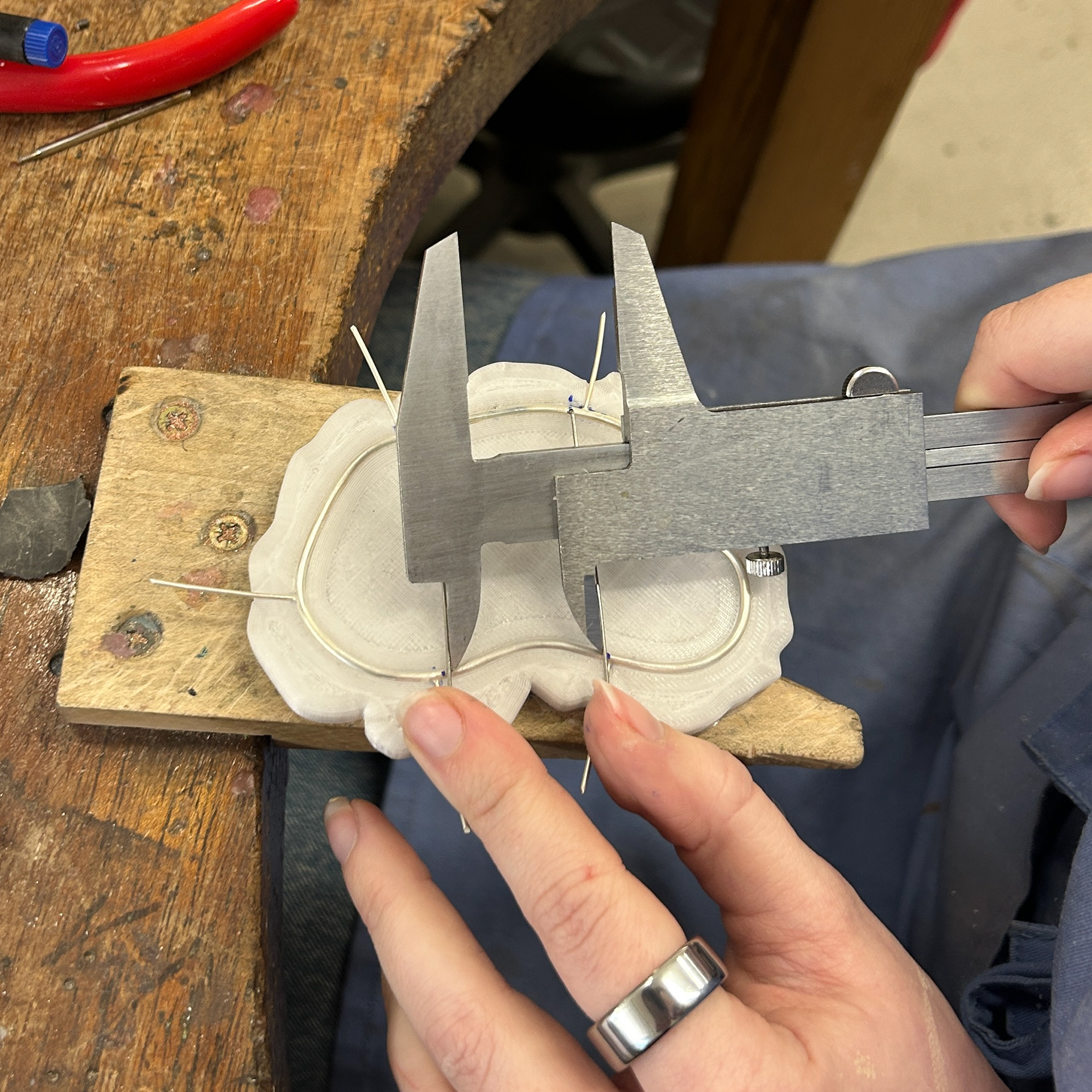
To continue making my final pieces, I had to make the silver bezels. I used 2mm silver wire for the bezel and 1mm silver wire for the prongs.
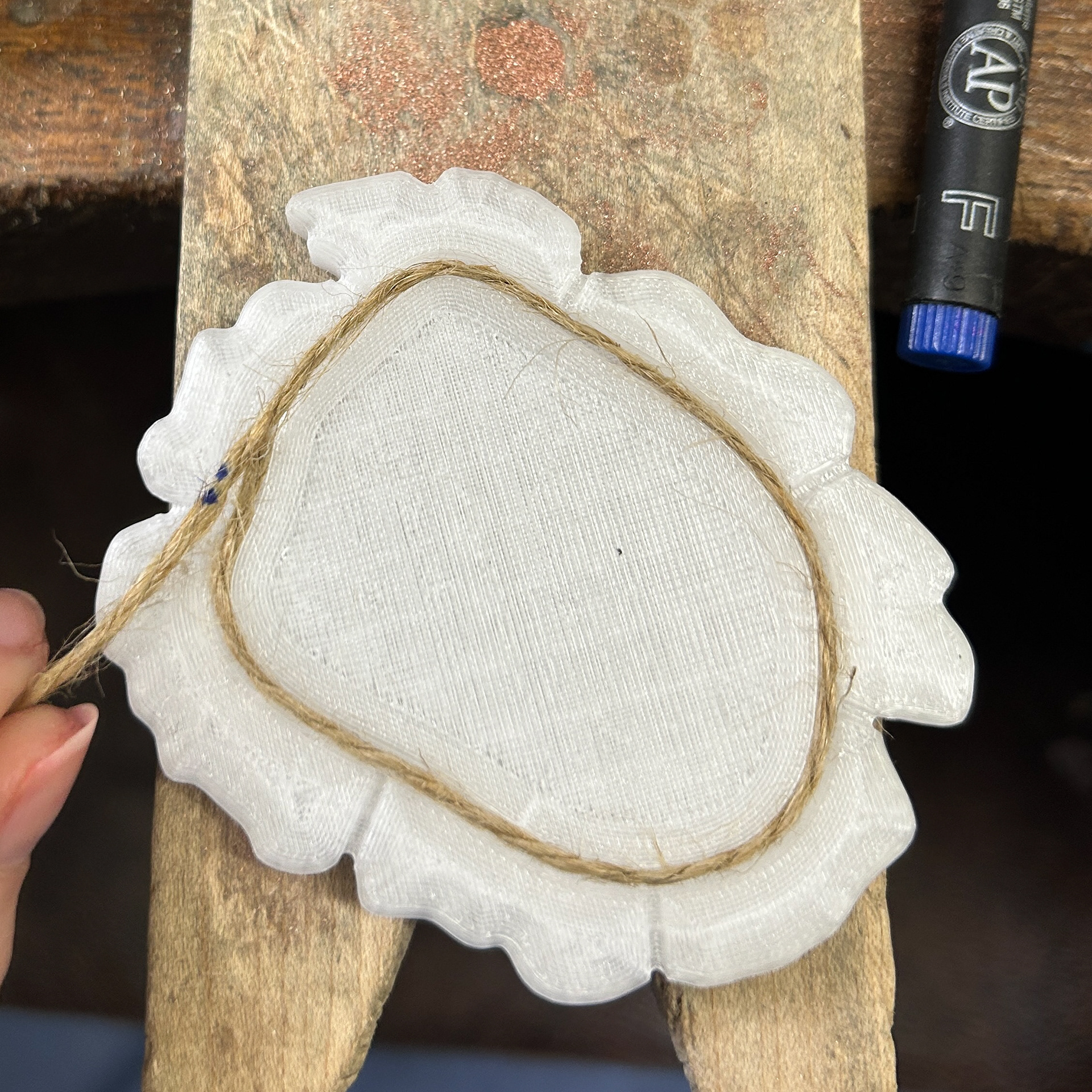
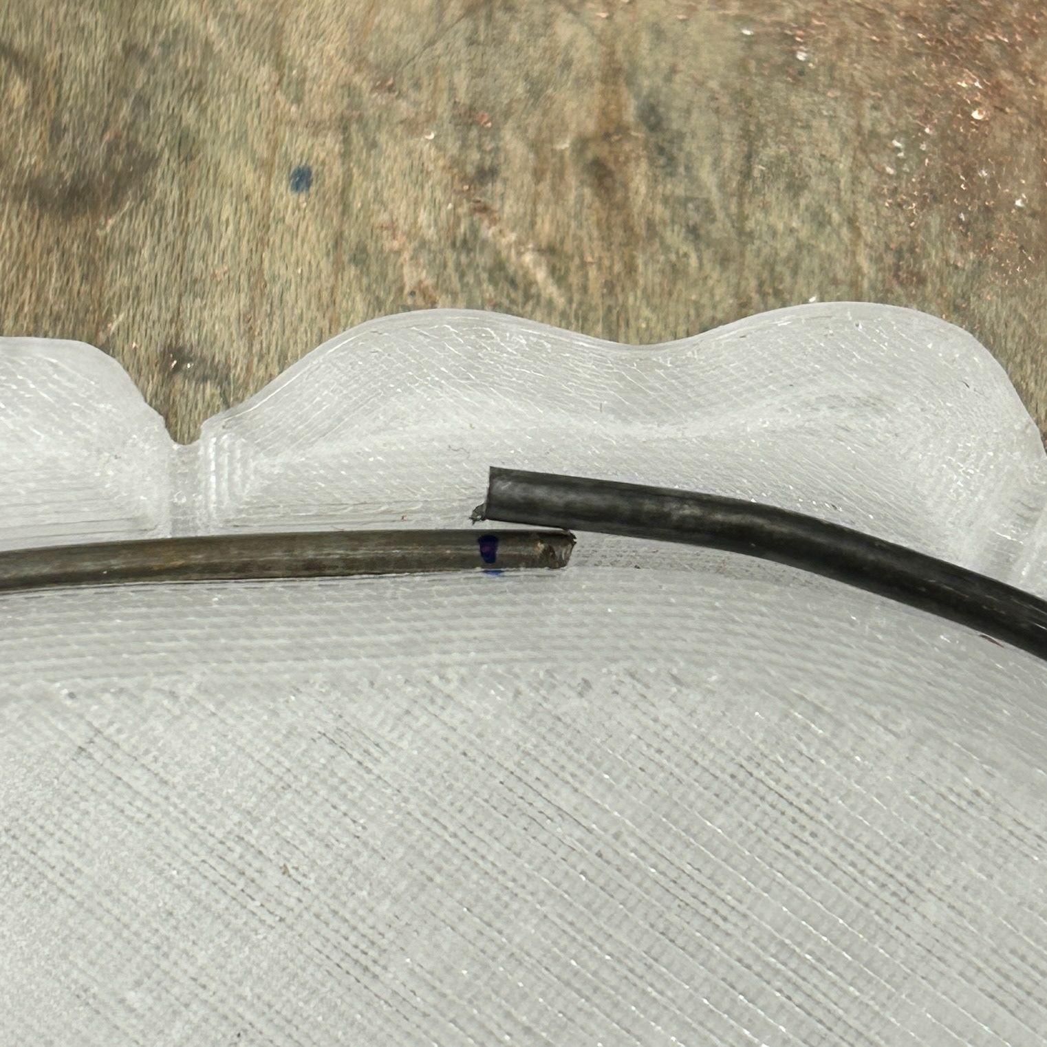
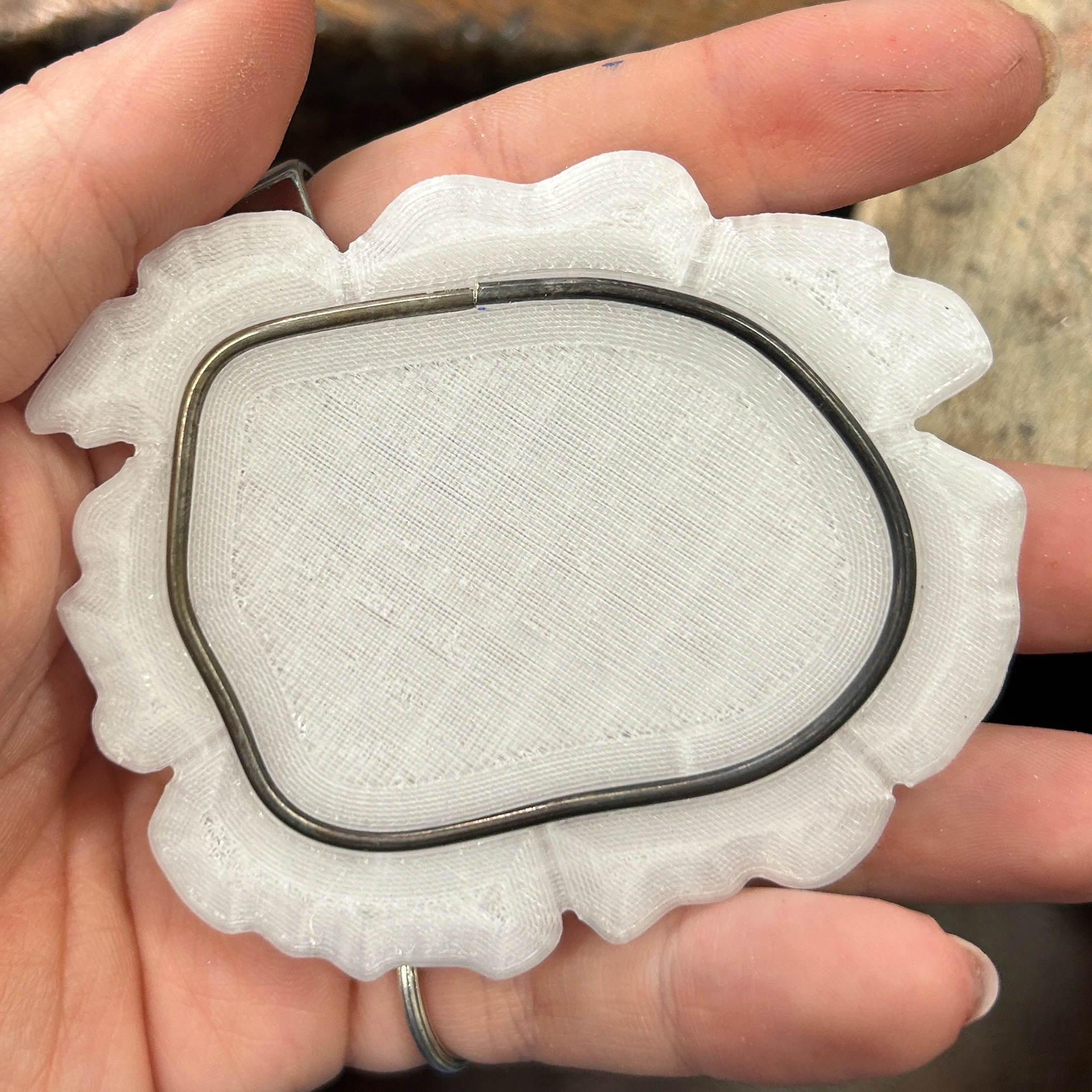
To measure how much wire was needed, I wrapped string around the bezel and marked out how much I needed. I could then bend the wire straight and mark where I needed to cut. I gave myself some excess just in case the wire wasn't fully straight, as this could be corrected with filing.
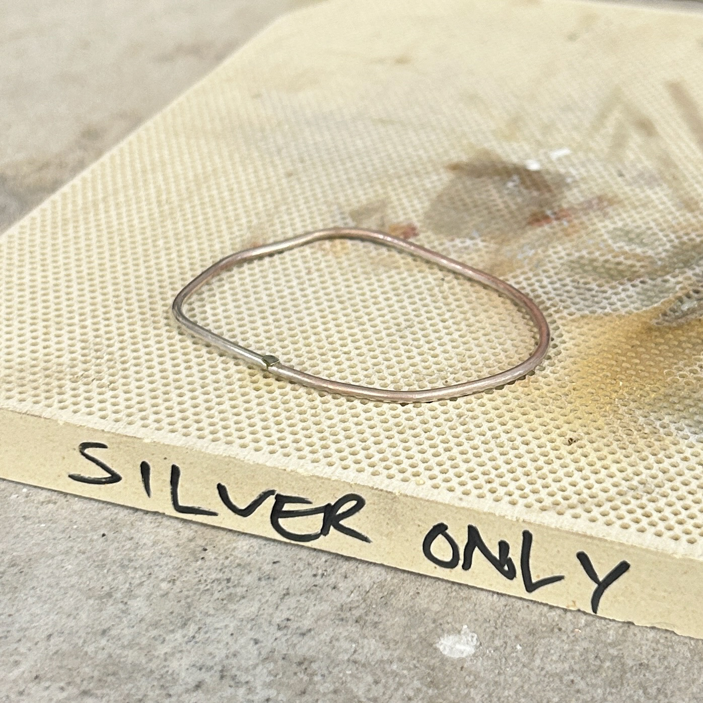
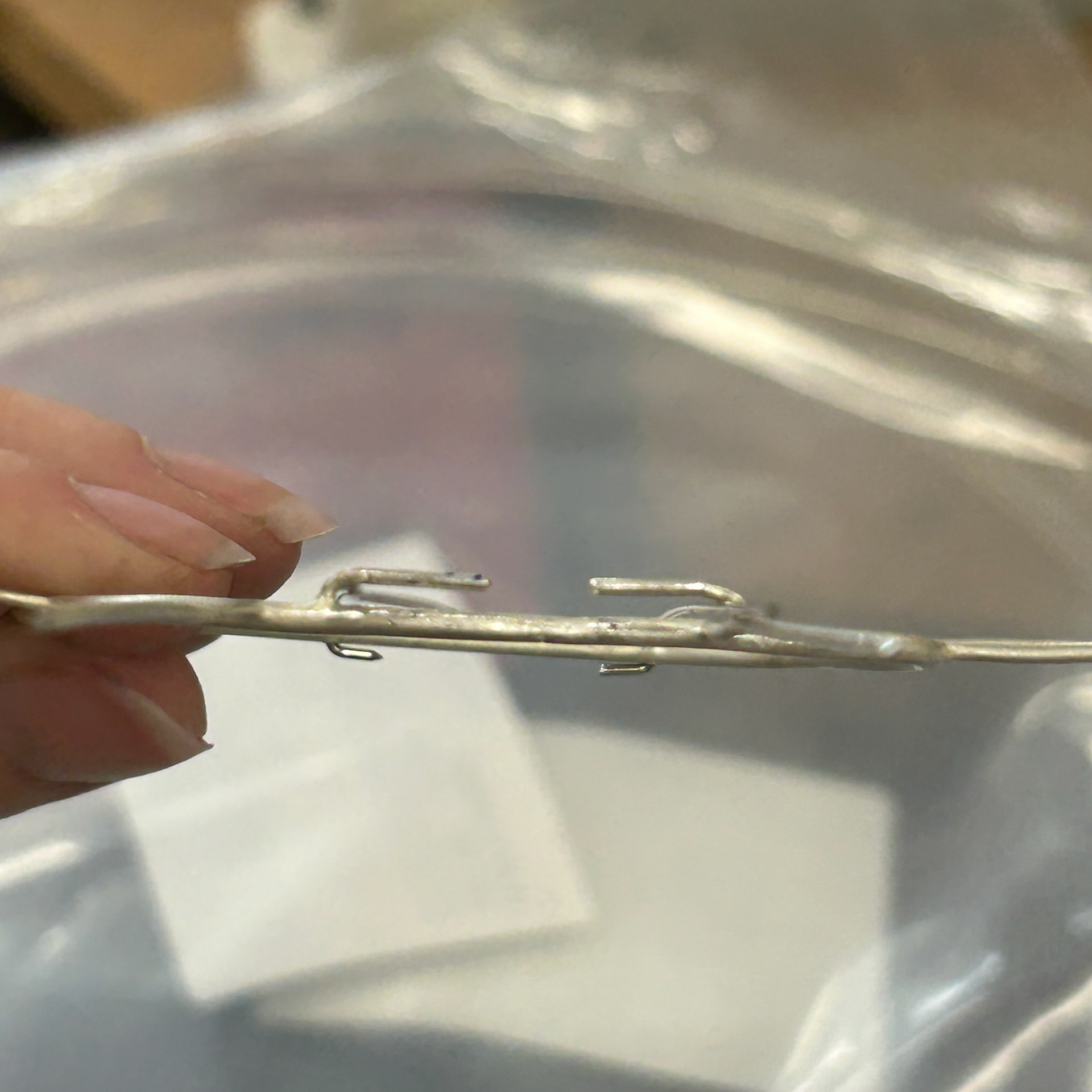
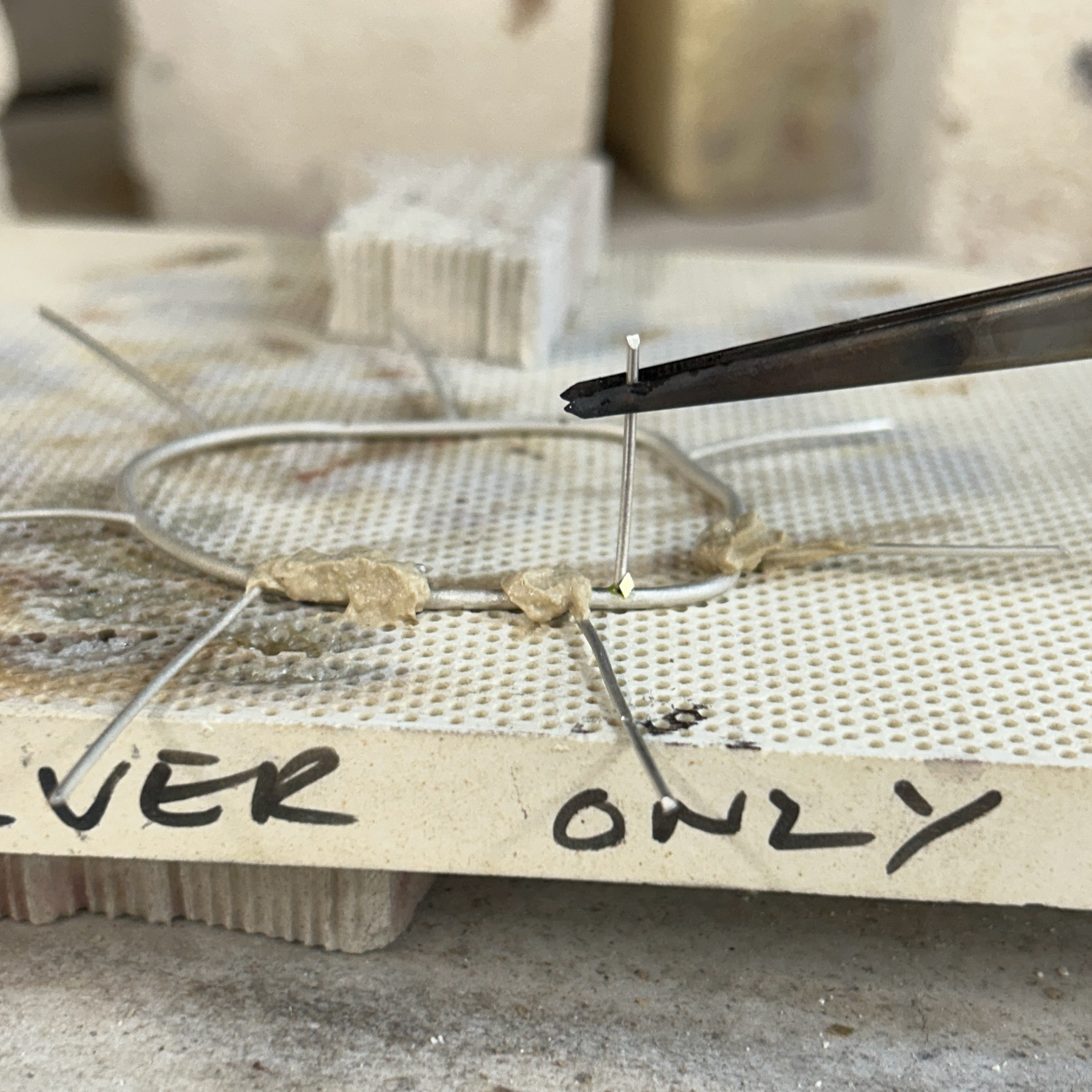
I then tested the fit, and once I was happy, I soldered this closed with hard solder.
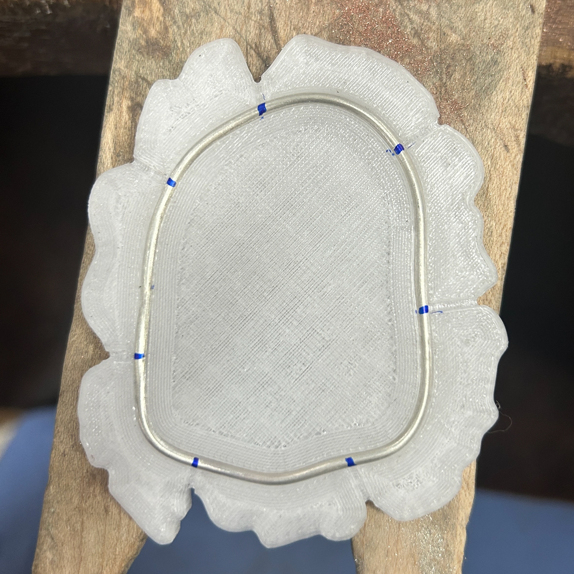
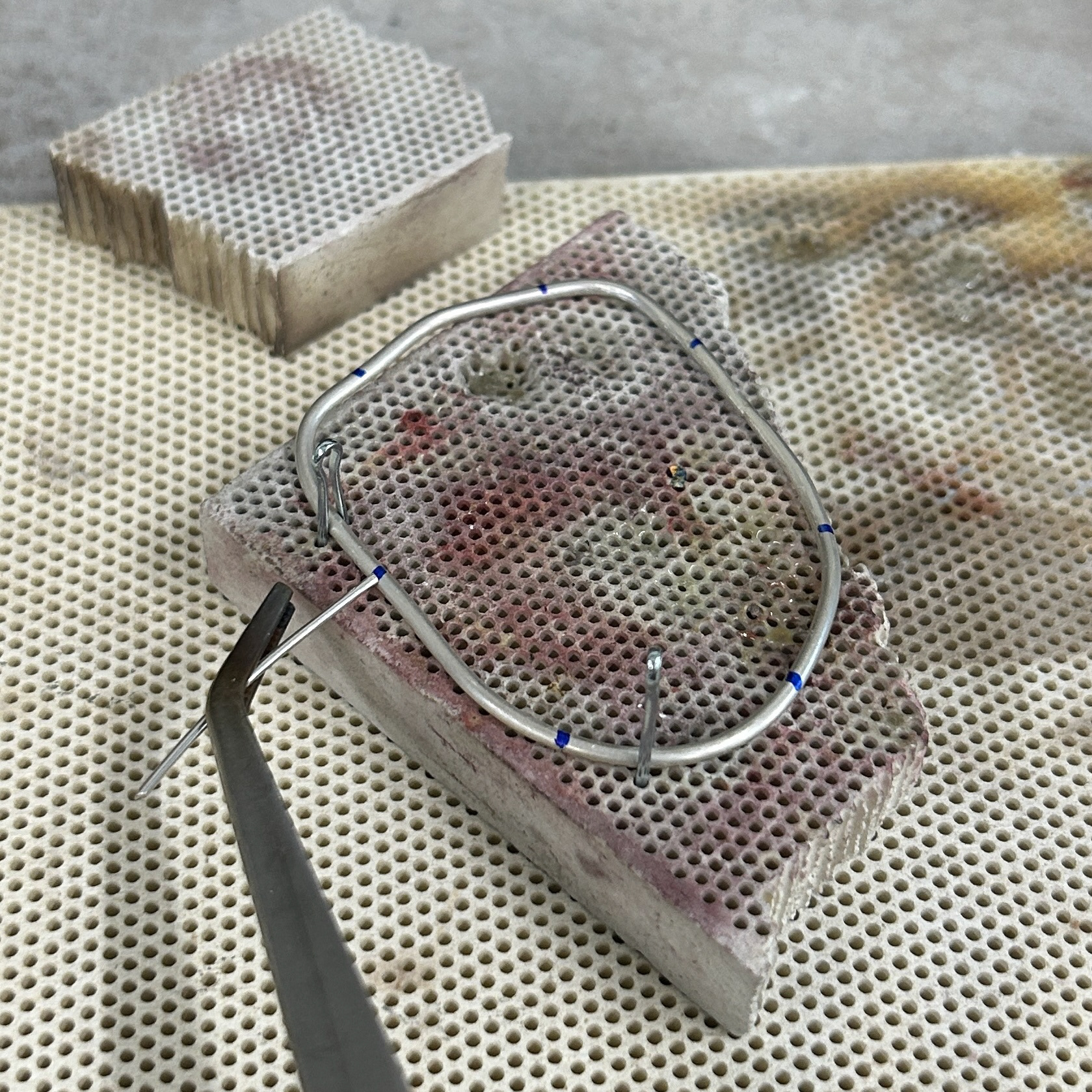
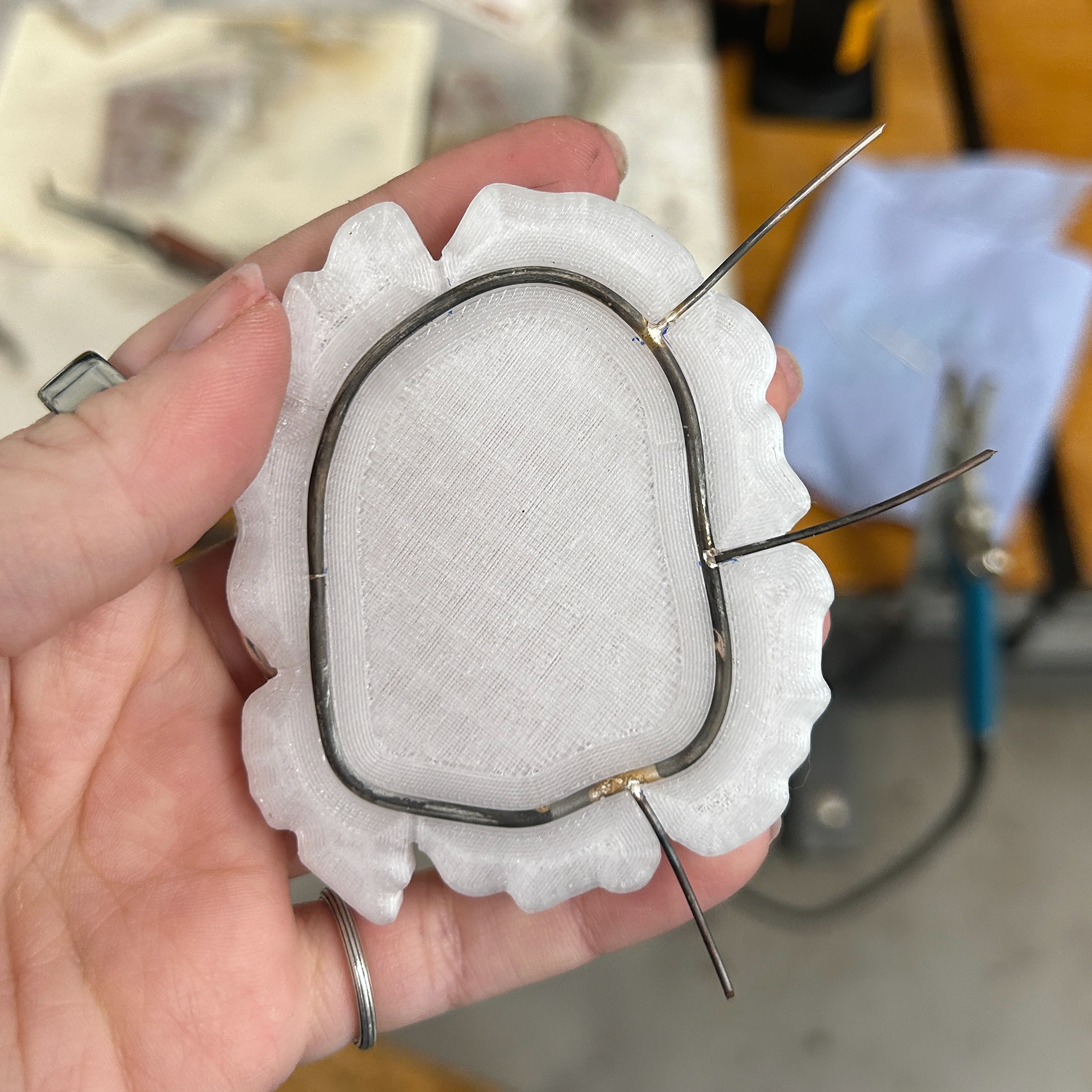
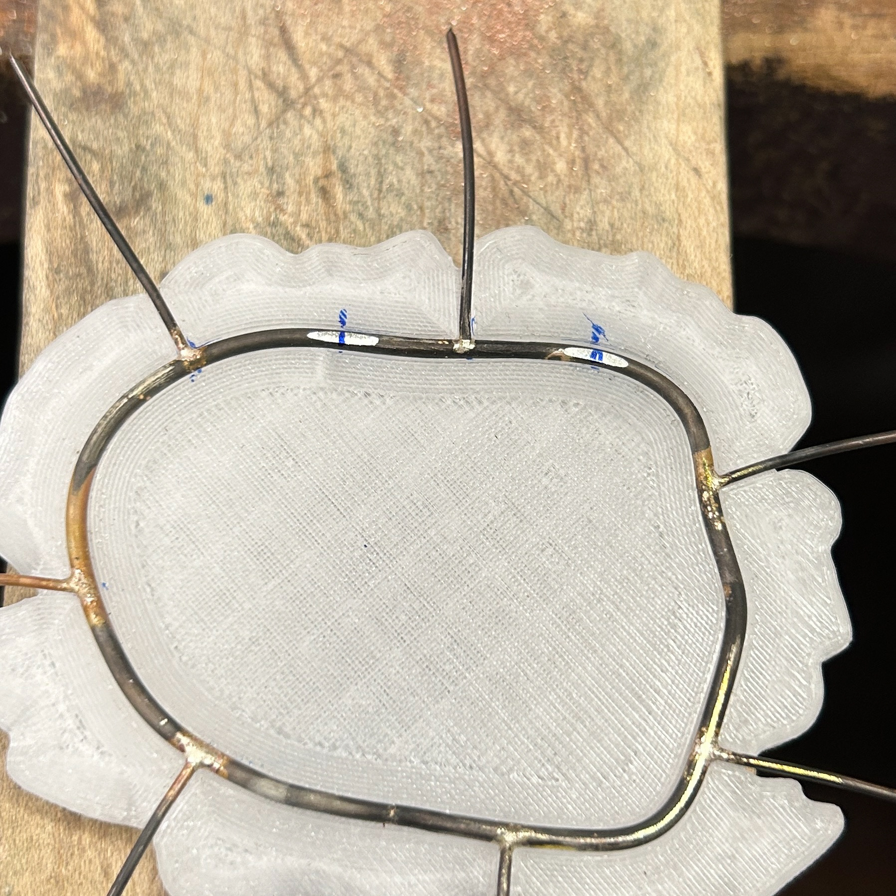
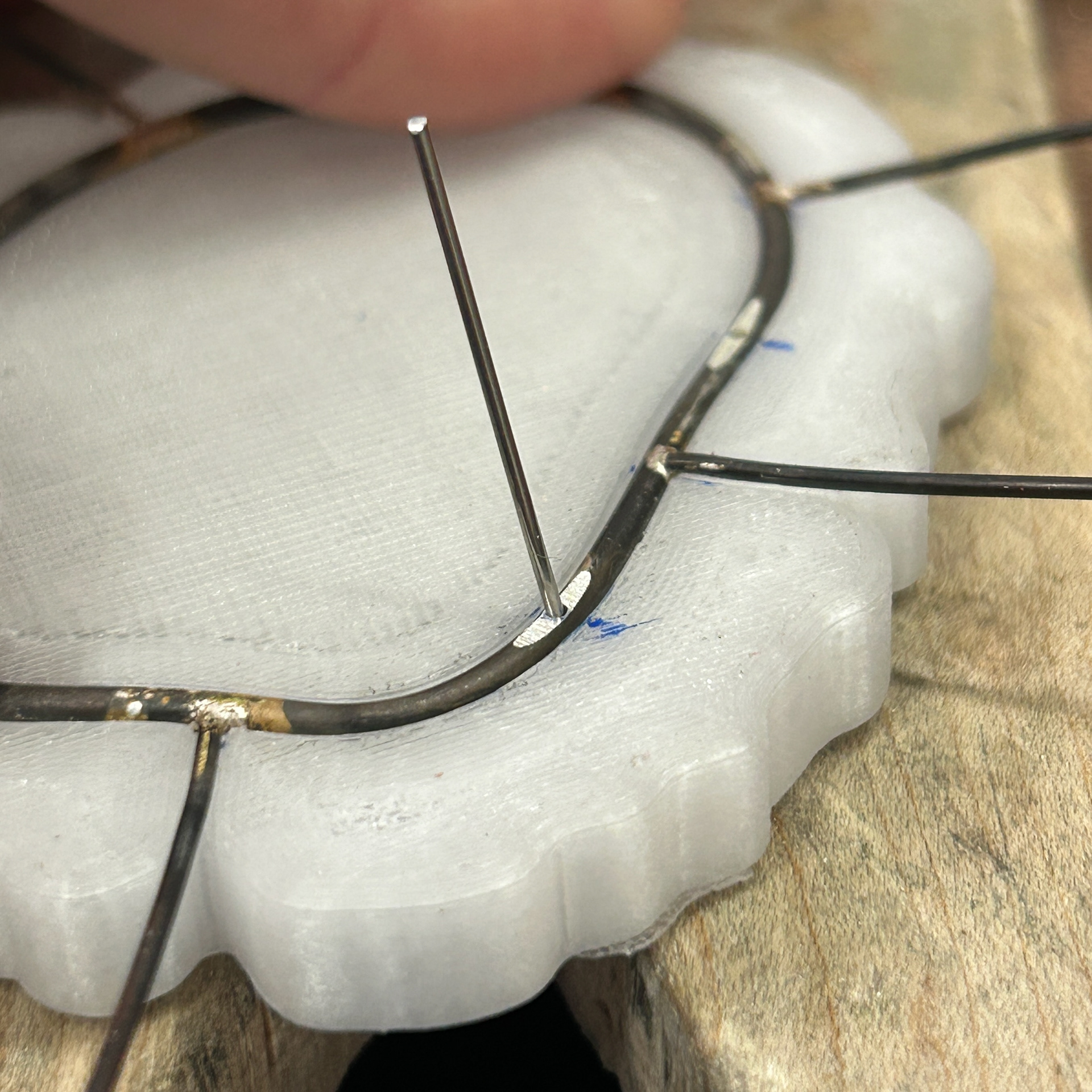
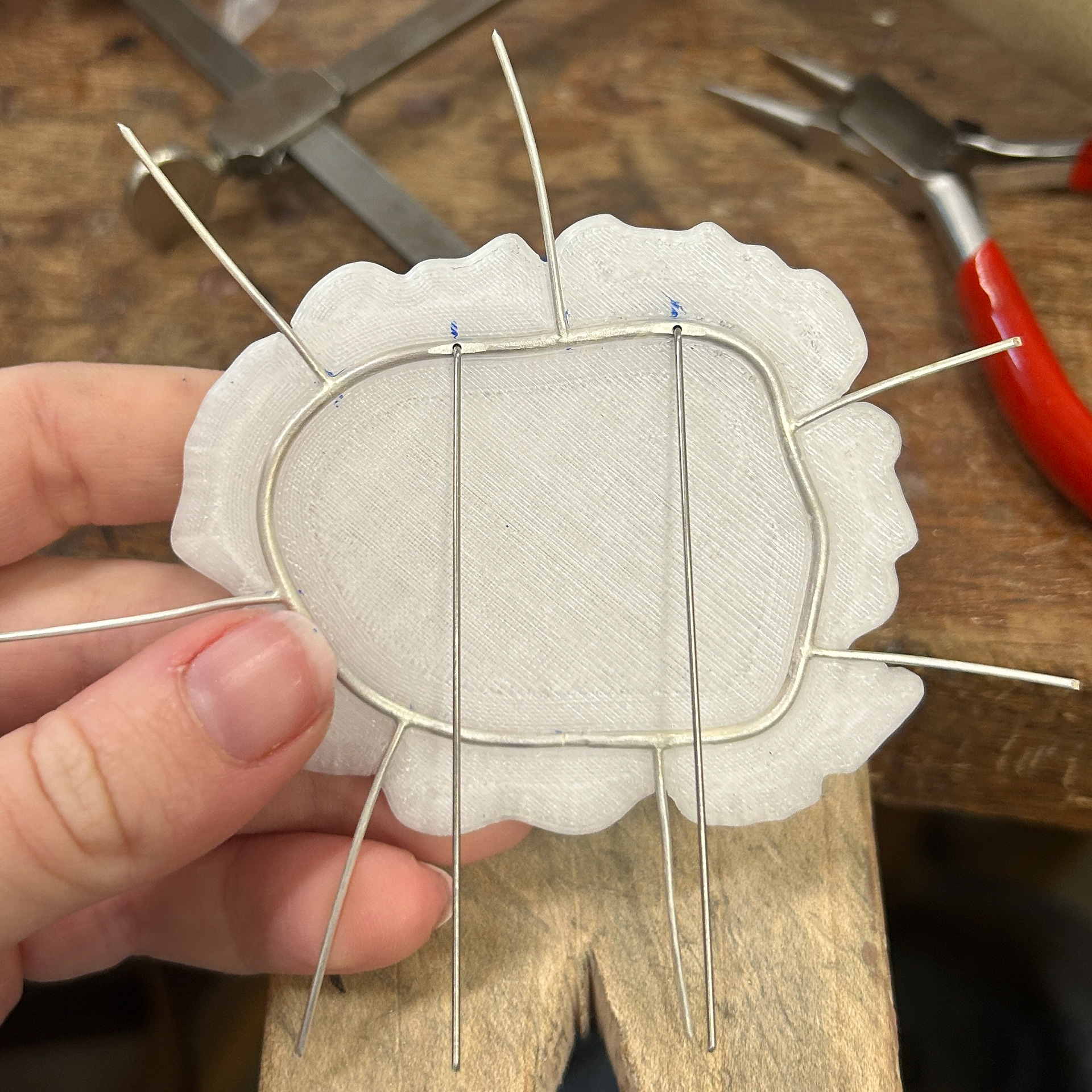
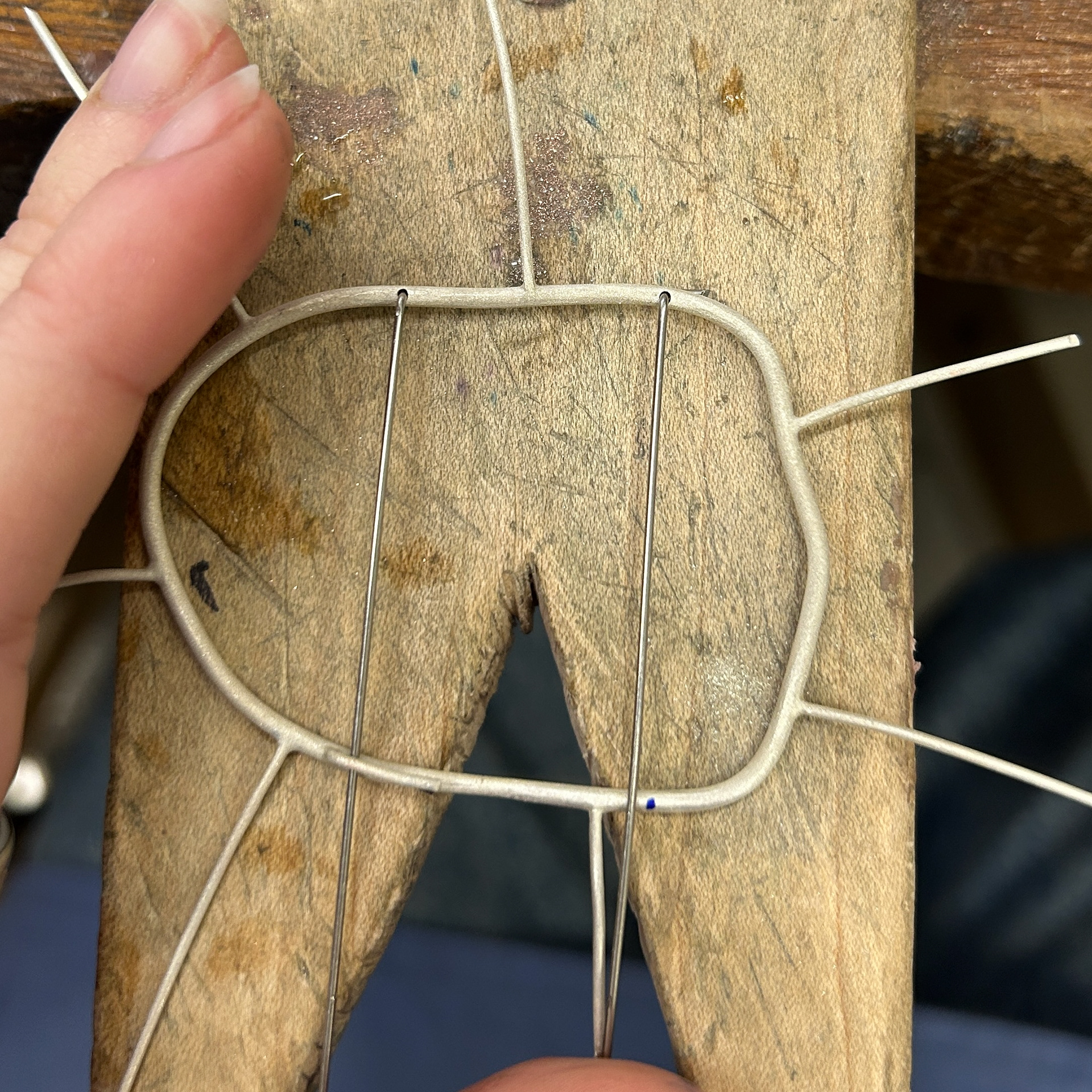
I then moved on to soldering the prongs on. I marked out where the prongs needed to be, and used medium solder to attach these. I was constantly checking the fit against my 3D print, just to make sure that none of the previous solders had moved at all. I kept the length of the prongs quite long, as this made using tweezers much easier, as well as reducing the risk of the wire melting. I will then be recycling this scrap silver wire in the future.
Once I was happy with the placement of the prongs, I moved on to drilling the space for the steel brooch pins. Knowing what I had learnt from my previous tests, I filled the profile of the wire down a bit, to make it easier to use a centre punch to create a guide for the drill. I then tested this against the wire and was happy with the fit.
After this first brooch, I decided to drill from underneath the bezel, as this meant that I would be able to leave the profile of the wire on the top of the brooch untouched. While I was able to sand away the file marks, I think it looked a lot better doing it from the back.
I then had to add the brooch hooks. To mark out where they needed to be soldered on, I used the brooch pins as a guide. I then used the same 1mm wire to make the hooks, soldered them on with easy solder, and bent them over using round-nose pliers.
After testing the brooch, I found that the hooks were slightly too close together. I asked Patricia for advice, and she suggested that I rebend one of the hooks as it was bent at a slightly different angle and that might help correct the angle of the pins. However, when I did this, the wire snapped. I had to go and file away the remainder of the wire and any of the solder and resolder the piece on. I decided that this time, I would solder the pin slightly further away from the previous one. I used Technoflux and Tippex on any of the joins to help prevent the previous solders from melting. I also used extra easy solder to help prevent any solders from running.
I was much happier with this placement and so moved on with repeating the same steps for the other 4 brooches.
I also made sure to use callipers multiple times to make sure that the placement of the brooch hooks were correct both before and after soldering.
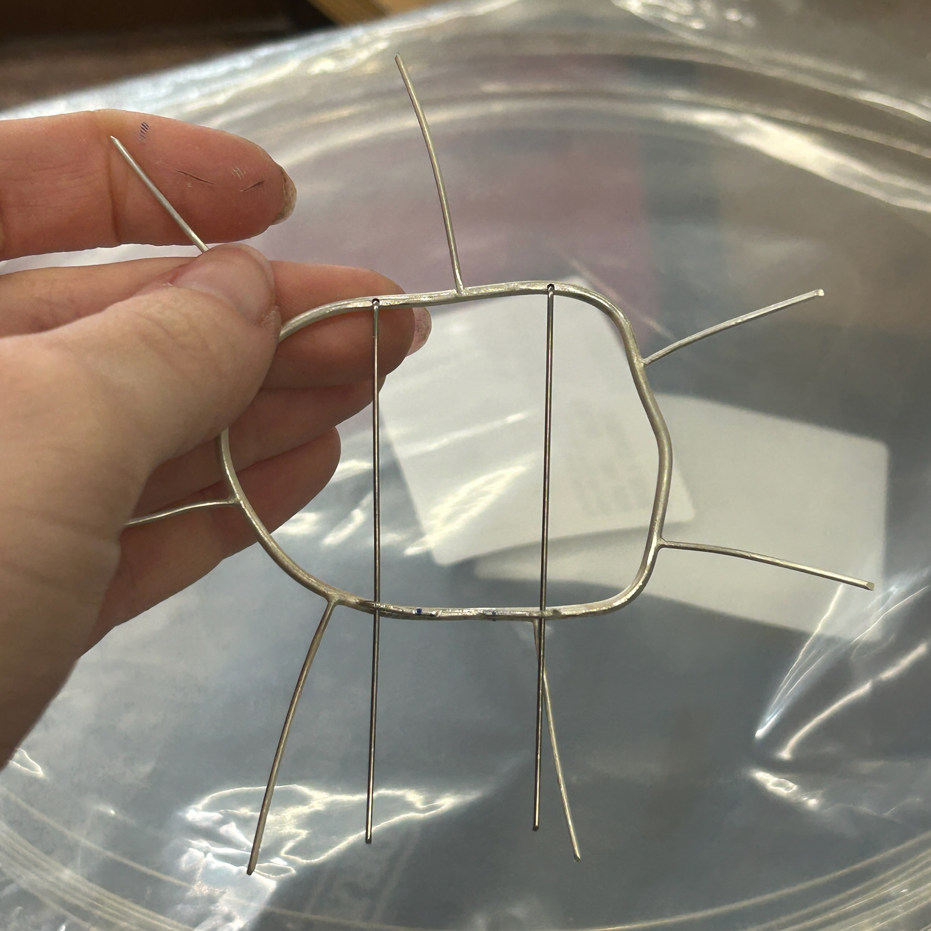
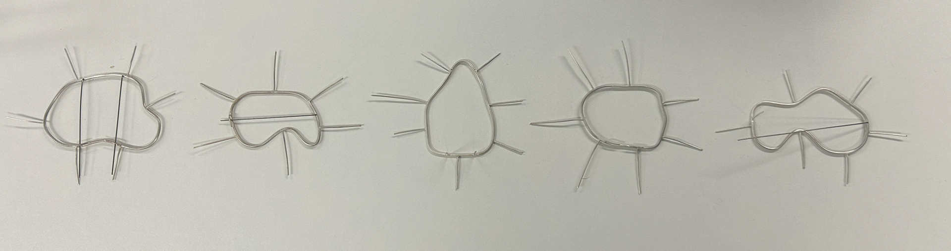
Final Silver Bezels
Silicone Moulds
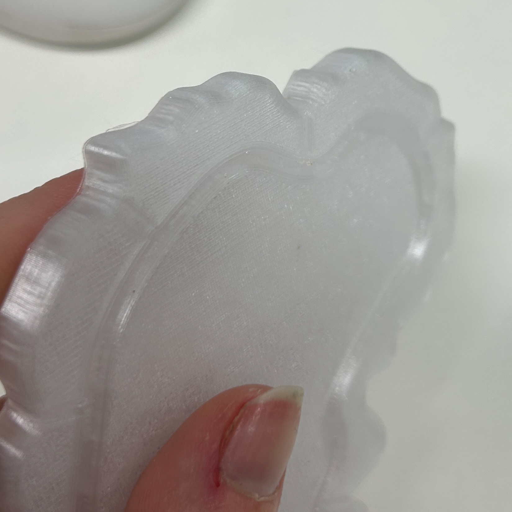
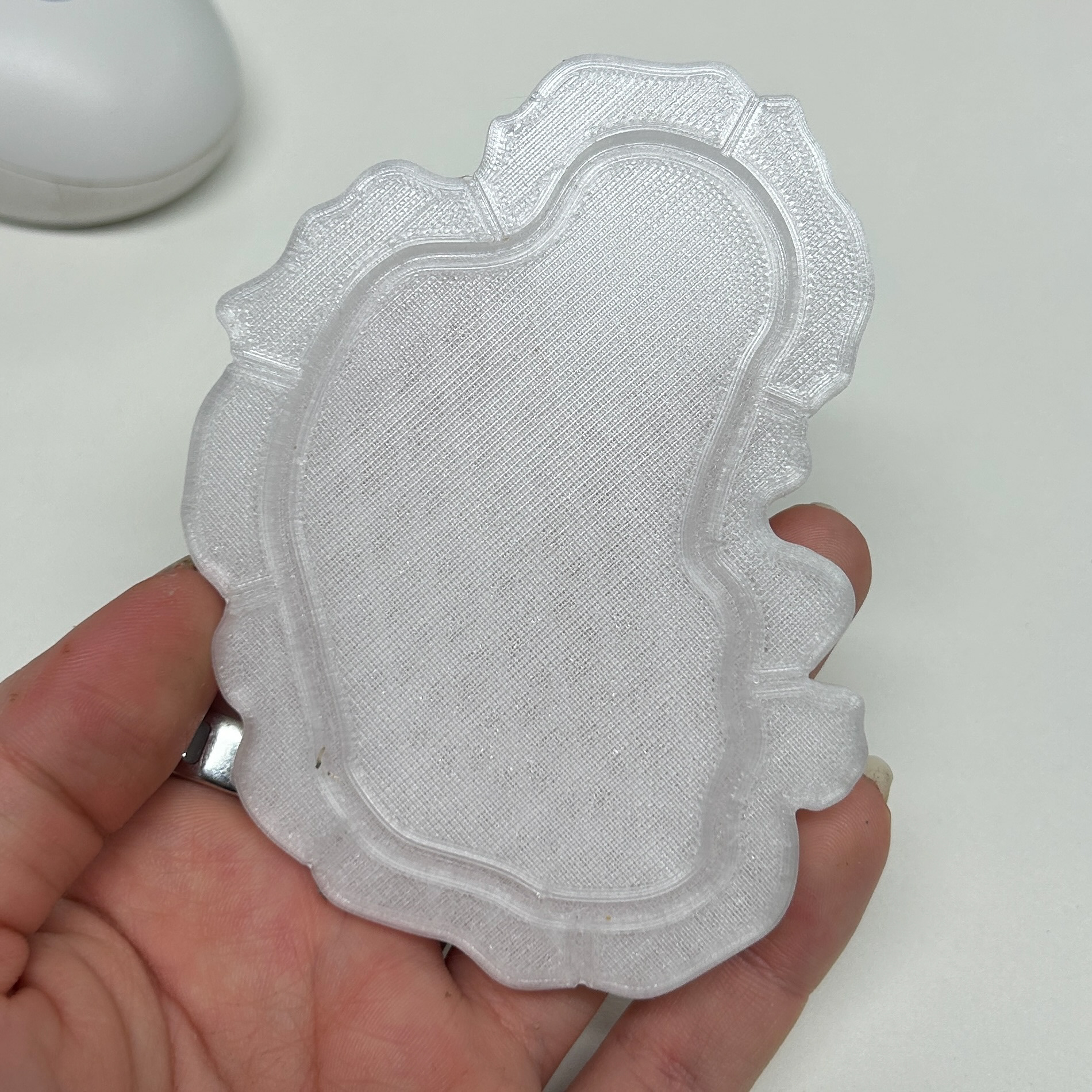
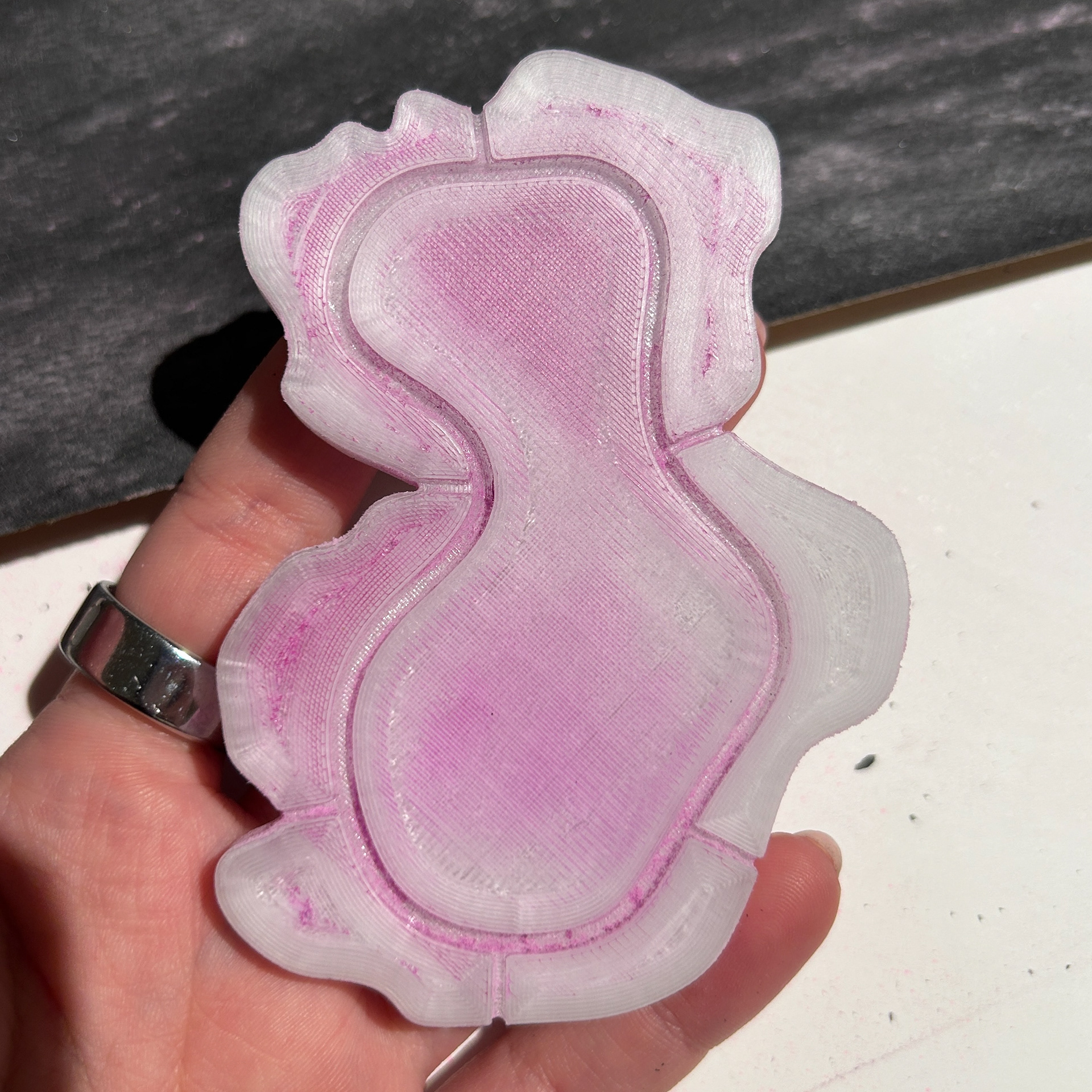
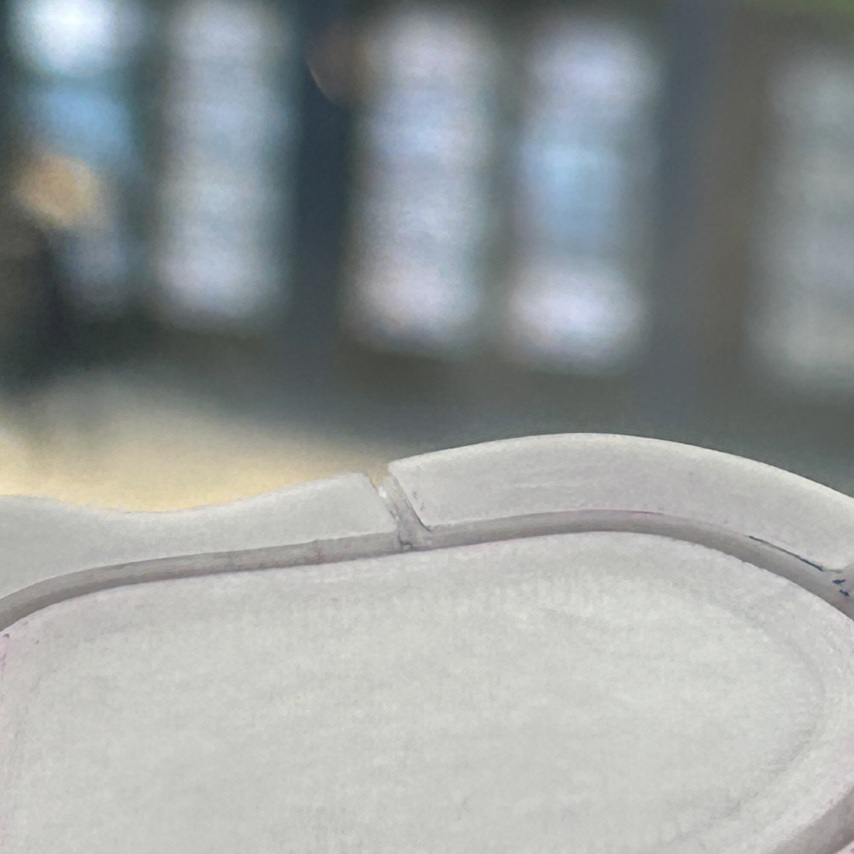
To make the silicone moulds, I followed the same methods I’ve used in the past. However, for some reason, these particular moulds were much more difficult to demould. As a result, that is why there is some cuts in the silicone where I had to carefully use a knife to break the seal between the two parts.
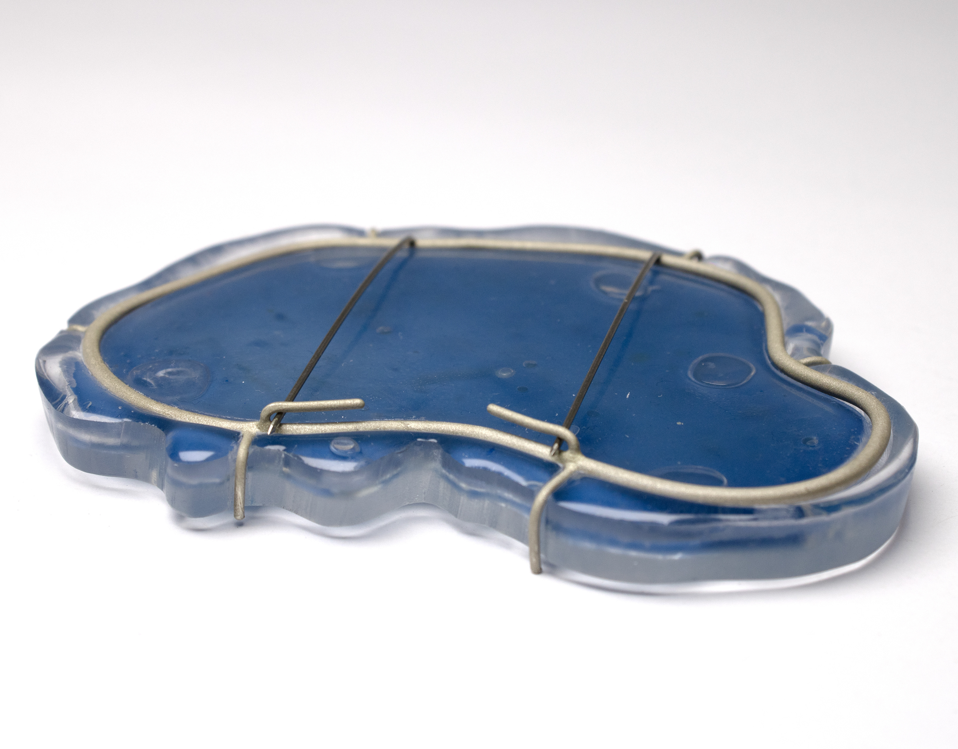
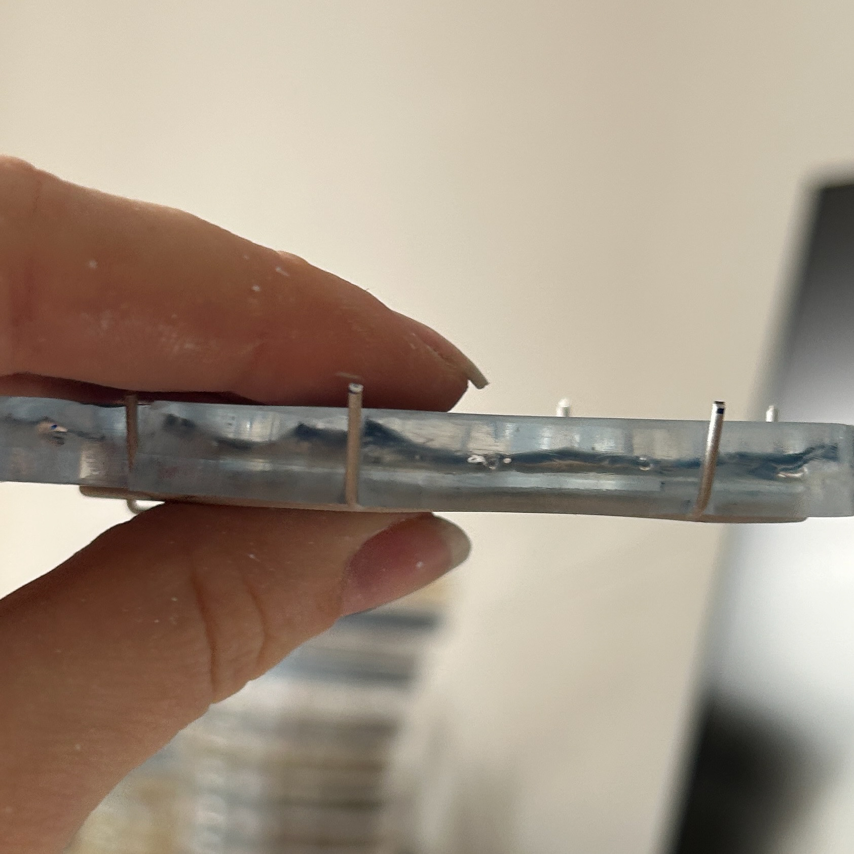
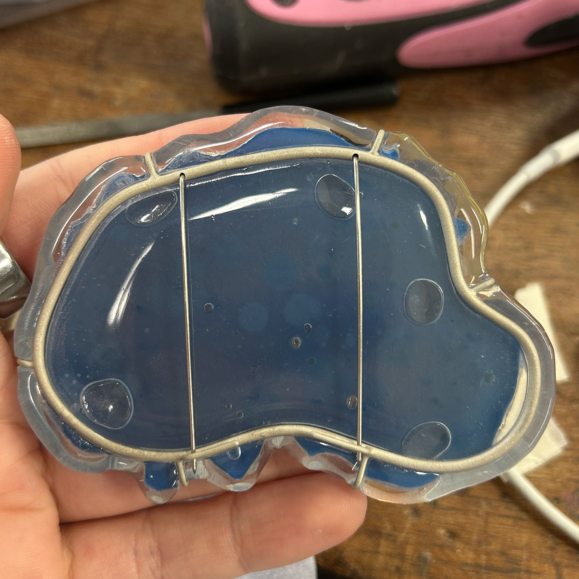
Resin
To encase my agar in resin, I used the same method that I have previously used, curing a layer, painting a layer and adding the agar, curing the outside layer, and then finally curing the top layer.
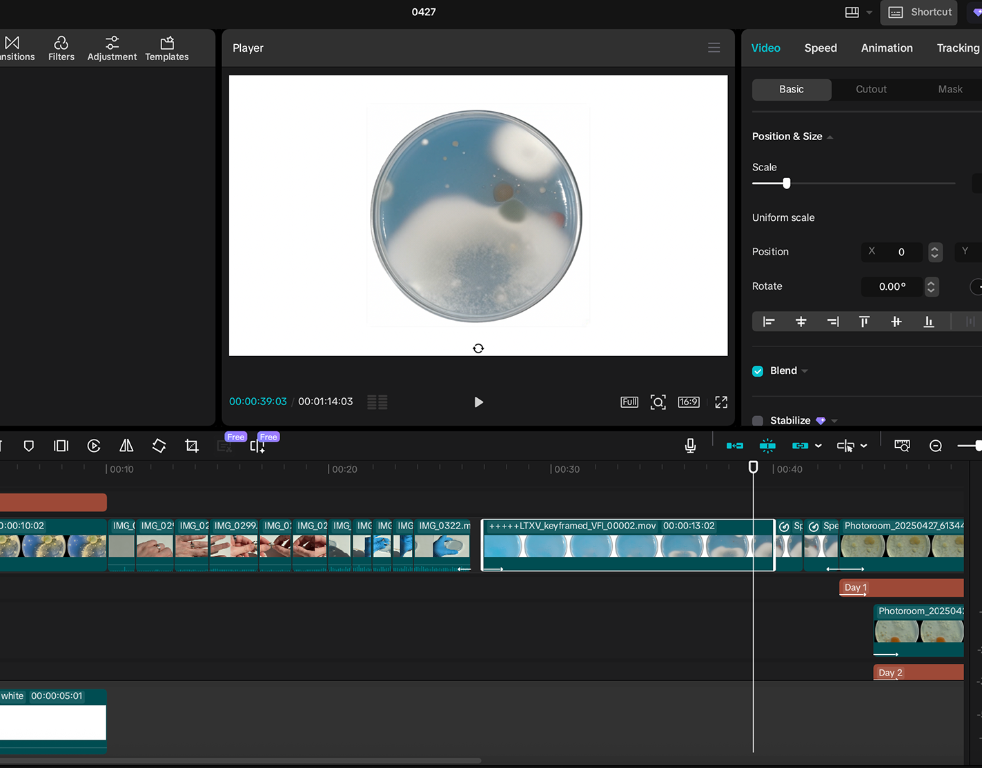
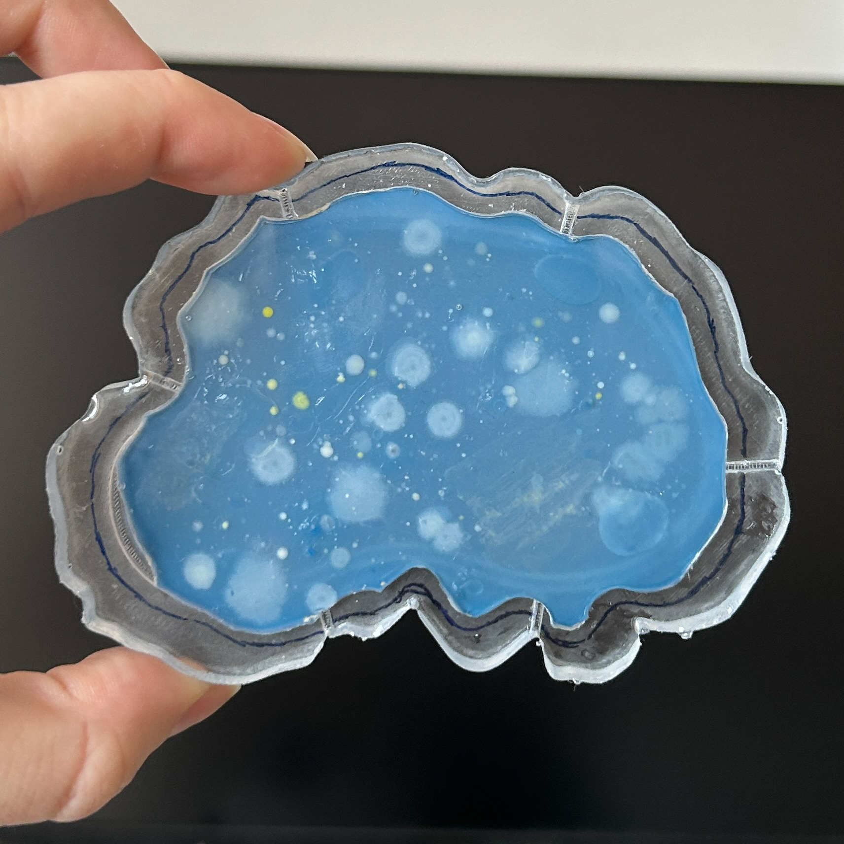
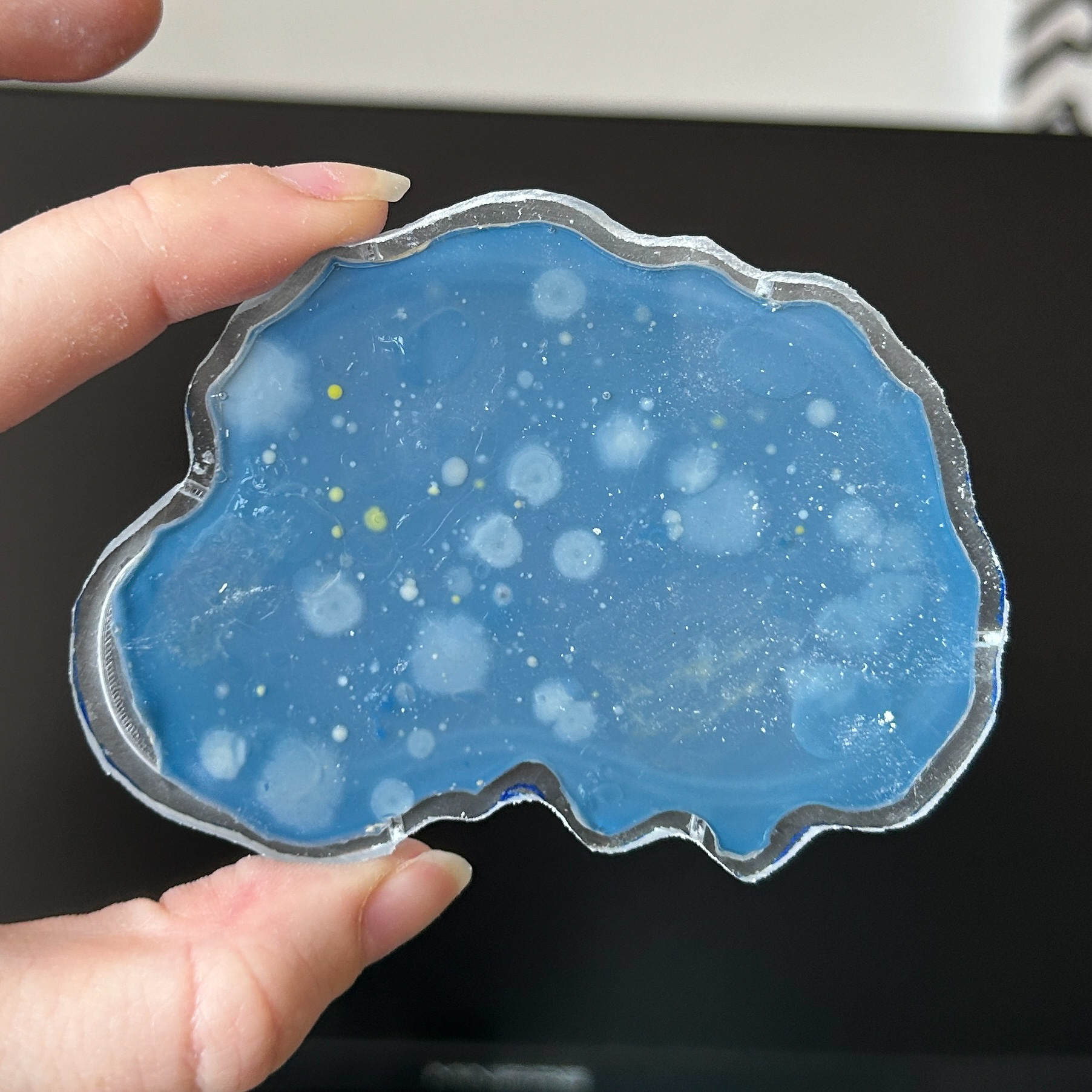
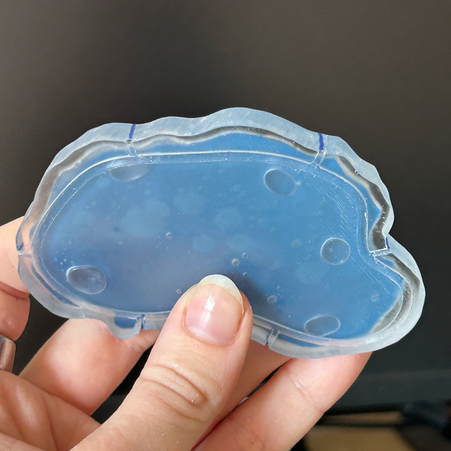
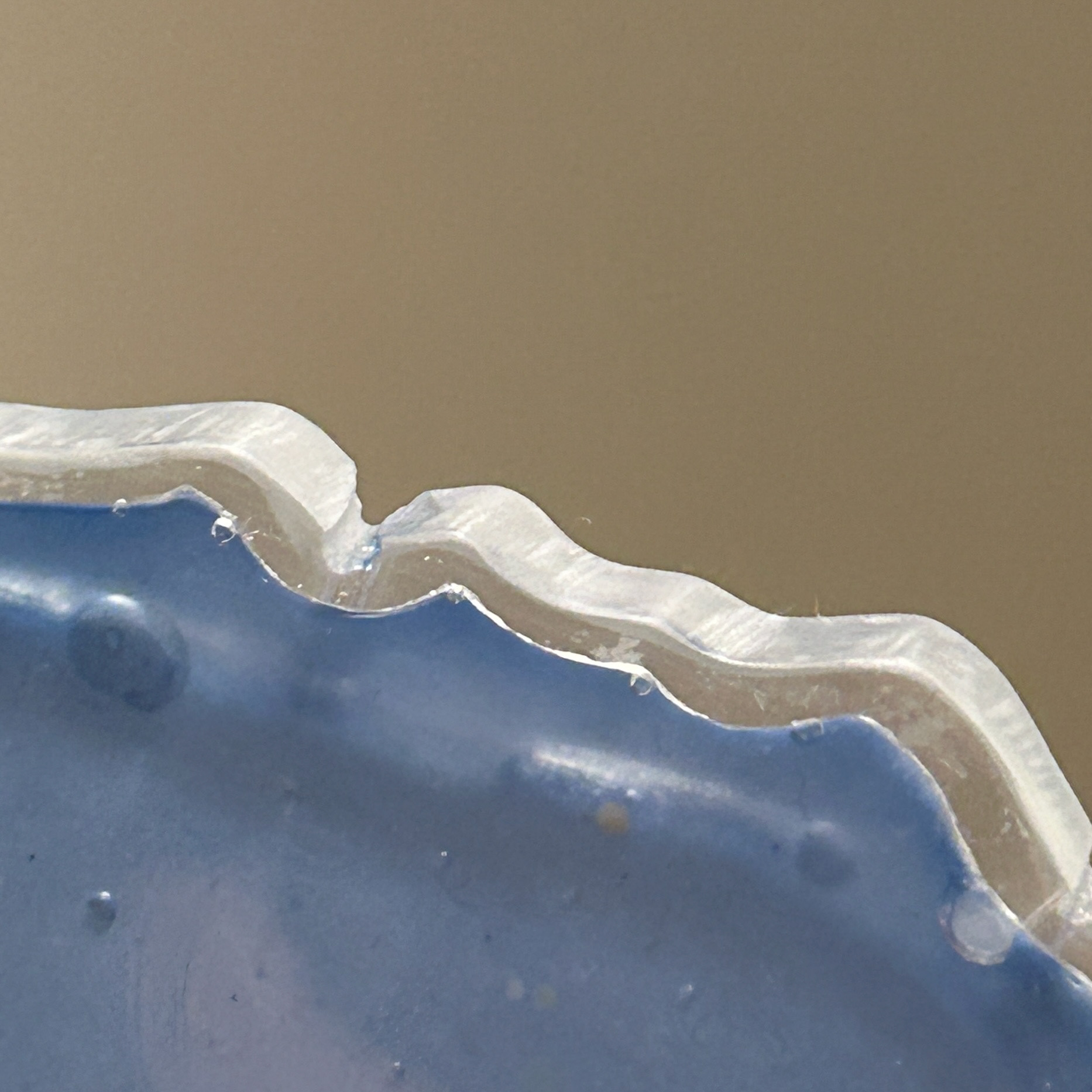
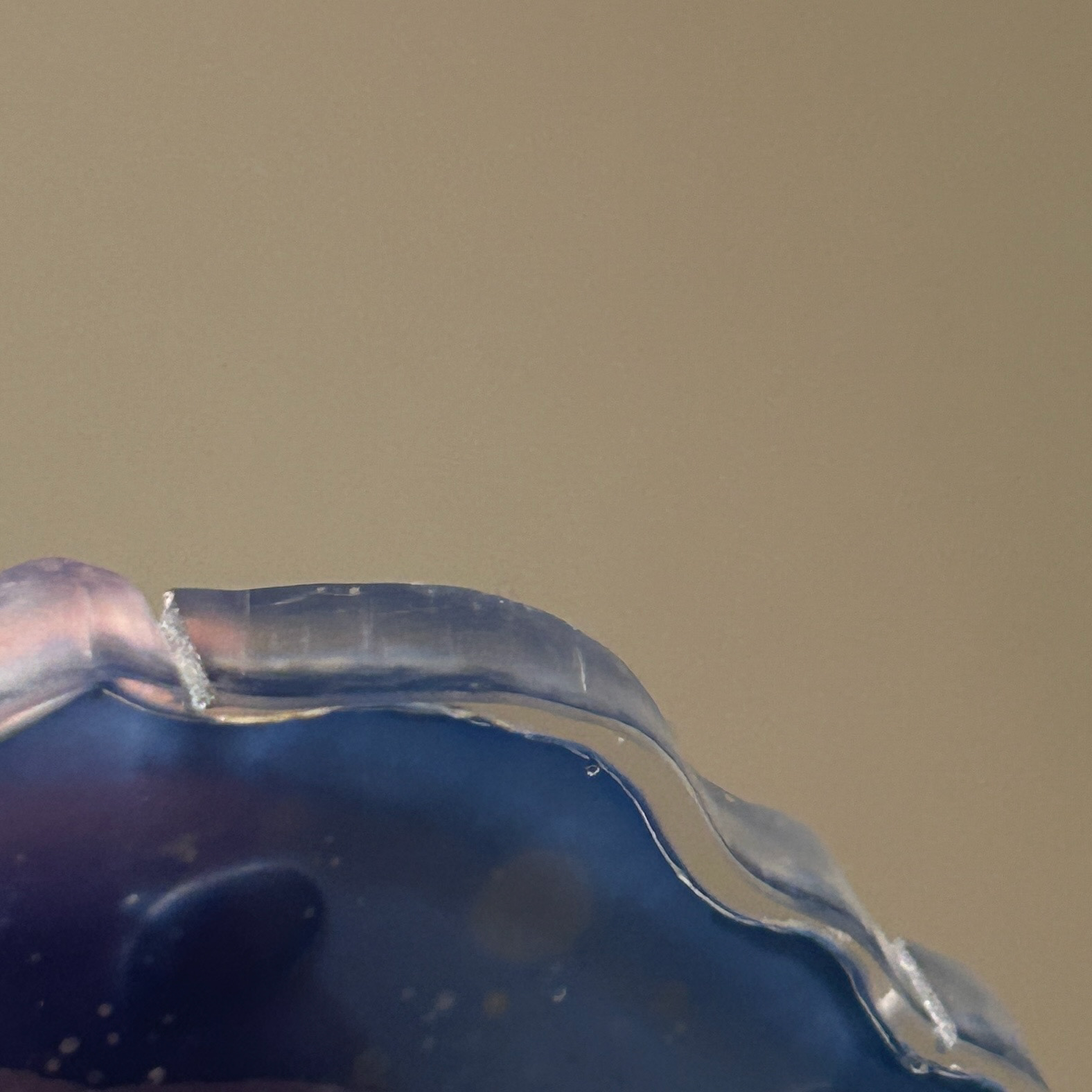
However, I found that when I went to add the agar to the cured layer of resin, the pieces had shrunk. This was most likely because of the heat causing the pieces to lose moisture and dry out, much like the agar in my timelapse video for my context film. While this was incredibly annoying as it meant that part of the bezel would shine through, my main concern was removing the excess resin. The shrinkage was inconsistent and so it meant that the resin boarder was also inconsistent.
I decided to experiment with using a thick saw blade to cut the excess resin off. I first tested this on a scrap piece of resin and the thick saw blade worked very well. This meant that I could trace around the shape of the agar and cut out a new boarder. While this was only outlining the shape that had already been made by the original shape of the bacteria, it meant that the new shape was incredibly similar.
I tried to keep a thick enough border so that the bacteria was still protected by the resin.
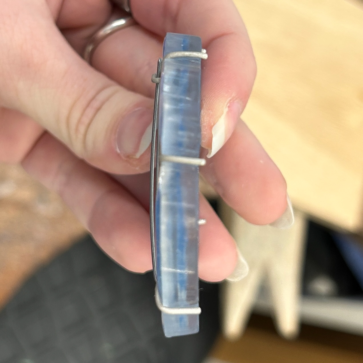
Before cutting
After cutting
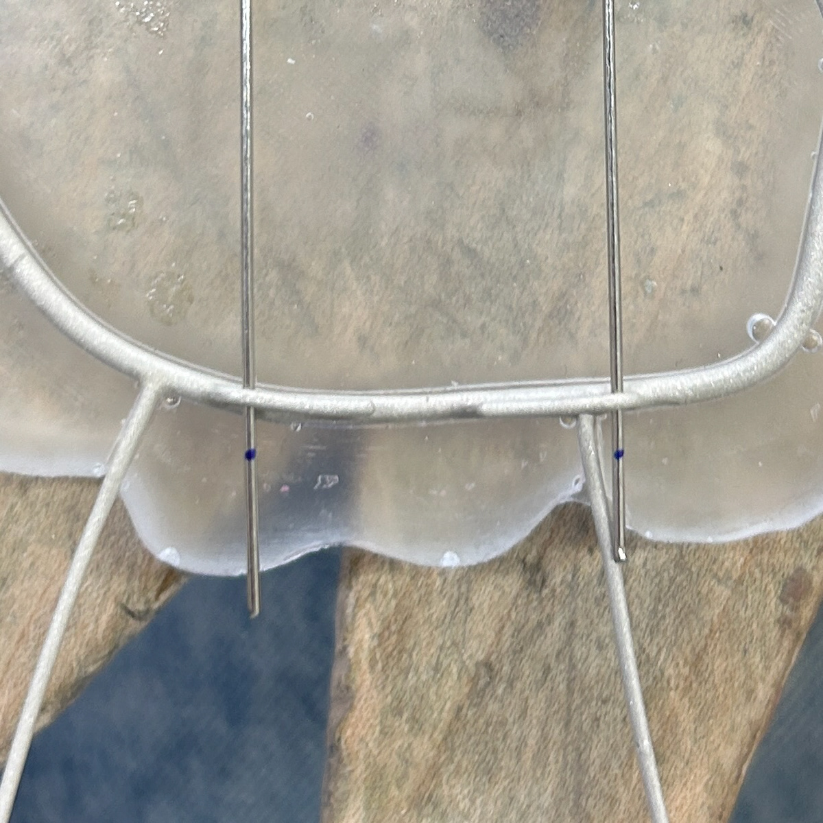
Marking out the prongs

Sanding out the prongs
Cutting out a new border also meant that I had to file the space for the prongs, as the ones I had 3D printed did not go as deep as I had cut. I used the markings on the back of the pieces to draw vertical lines where the prongs needed to be, and then used a diamond drill bit to drill out the space for the prongs. Most of these went perfectly fine, however I found that a couple of them went slightly to the left / right, which I have had to correct with sanding.
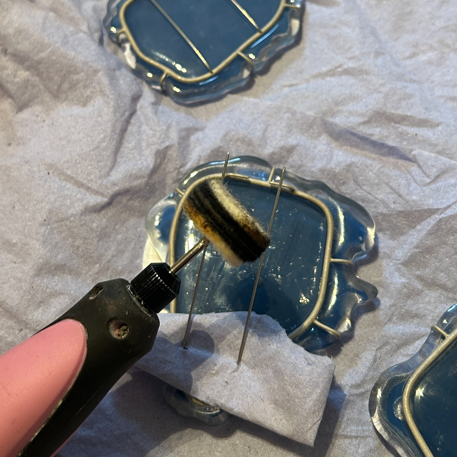
Polishing
When finishing my pieces, I aimed for a satin-like polish on the sides to complement the matte texture of the sandblasted silver. I gradually worked through various grits of sandpaper and polishing compounds, refining the surface until I achieved the subtle, even finish I was aiming for.
For the back of the pieces, my goal was a perfectly clear, glass-like surface. After experimentation over Christmas, I found that the most effective way to achieve this was by applying a final layer of resin as a 'polishing' coat. To prepare for this, I had to sand the resin back to 320 grit, a step I hadn’t previously had to do on my tests. However, when I tested this method on a sample piece, it had better results than traditional polishing techniques. I do question whether this is because there was already some surface tension on the tests I had been doing on my old 3D prints that I hadn't taken into account. I did find that this method worked better on the areas with less surface area, potentially due to surface tension again.
In hindsight, had I known this earlier, I could have avoided sanding beyond 320 grit and saved myself a significant amount of time. Although the learning process was labour-intensive, it was ultimately valuable.
After assembling my brooches:
I decided to leave the front of the brooches untouched, as attempting the same resin polishing technique felt too risky on such a large surface area, especially since I knew in my earlier tests that smaller surfaces polished better. I wasn’t fully confident in the outcome and was concerned that the resin might pull away from the edges. Initially, I thought the marks left by the resin reacting with the moisture in the agar added to the narrative, highlighting the interaction between the materials, but after assembling the brooches, I realised I didn’t like the effect at all.
I decided to leave the front of the brooches untouched, as attempting the same resin polishing technique felt too risky on such a large surface area, especially since I knew in my earlier tests that smaller surfaces polished better. I wasn’t fully confident in the outcome and was concerned that the resin might pull away from the edges. Initially, I thought the marks left by the resin reacting with the moisture in the agar added to the narrative, highlighting the interaction between the materials, but after assembling the brooches, I realised I didn’t like the effect at all.
Despite using masking tape to protect the surfaces, the fronts became even more scratched during assembly in the workshop. Removing the resin now would involve moving the prongs, which could easily snap, and that risk felt too great. I had already used up my contingency due to earlier issues with bacterial growth and knew I wouldn't have enough time to fix any major errors. Rushing the process could have made things worse, so I had to carefully consider whether to leave the pieces as they were or attempt a fix.
While I’m disappointed in myself for not anticipating how these imperfections might appear to someone viewing the work for the first time, especially under harsh exhibition lighting, I know I’d be more disappointed if I ruined the pieces entirely and had nothing to submit. That said, I fully intend to refine them in time for New Designers, ensuring they are shown at their best and that I have enough time to correct any further issues that arise.
Finishing the Prongs
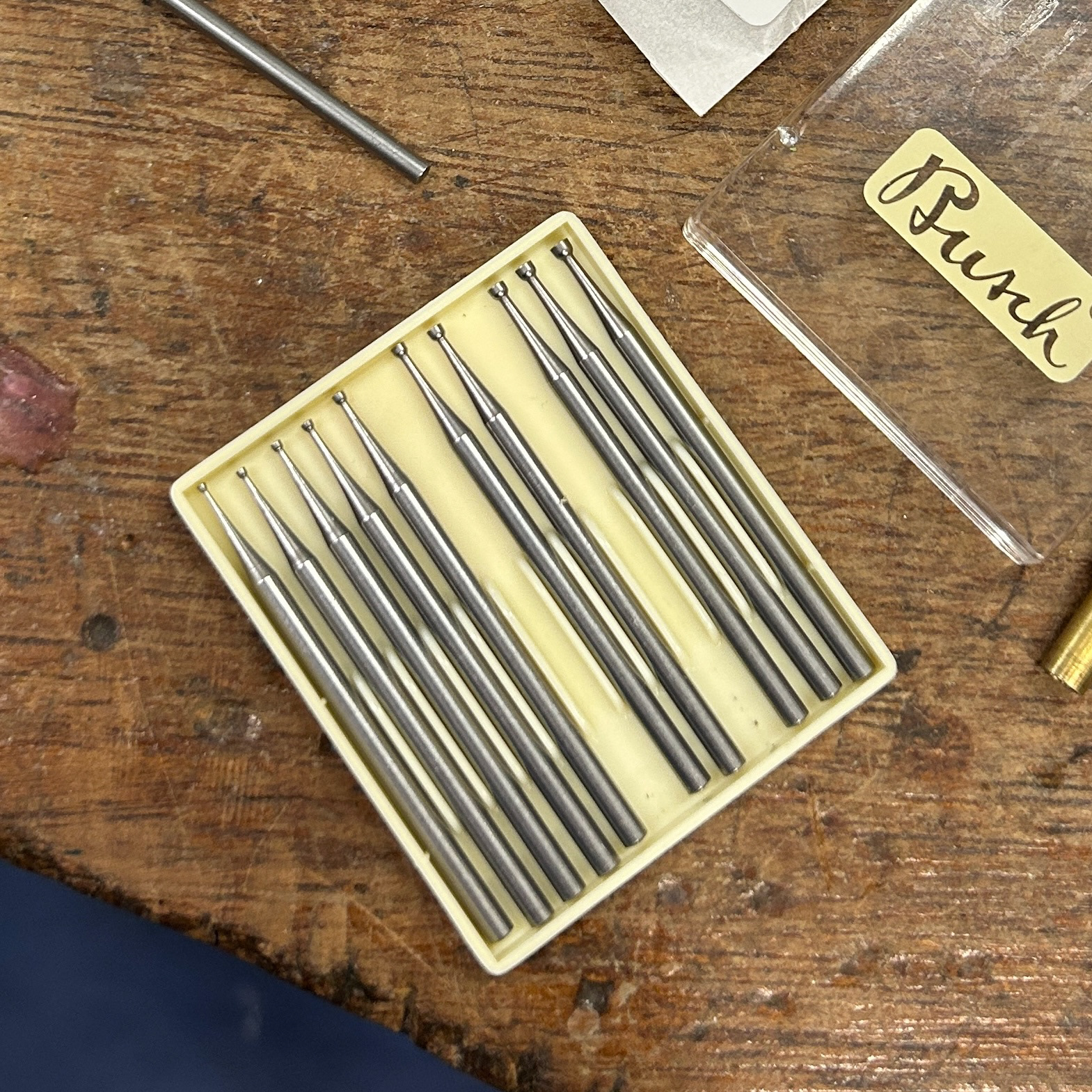
Before using the cup burrs
After using the cup burrs
After using a cup burr
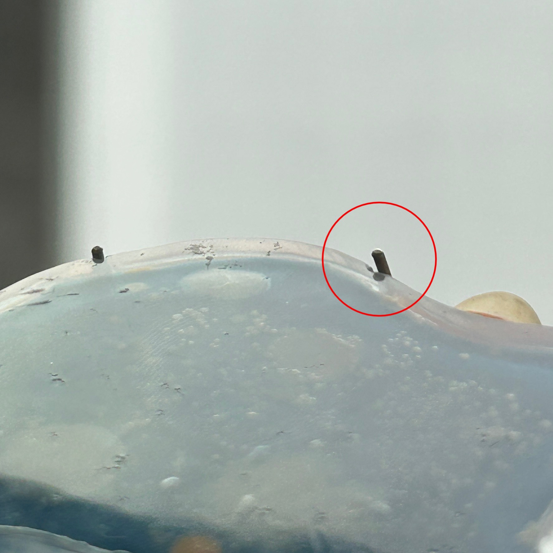
Uneven prong
To finish the prongs I used cup burrs to help create the consistent rounded finish on all of the prongs and the brooch hooks.
To finish the prongs, I first had to cut them down to size. After revisiting my notes from 'To The Point', I realised that I wanted small, discrete prongs, hence why I then cut them down so much compared to what I had soldered on. I then filed these flat and rounded them all using the cup burrs.
After cutting and filing the prongs, I found that one of them was still too high. Unfortunately, the sandblaster had broken again, and so I was unable to fix it. I will be going back to fix this in time for New Designers.
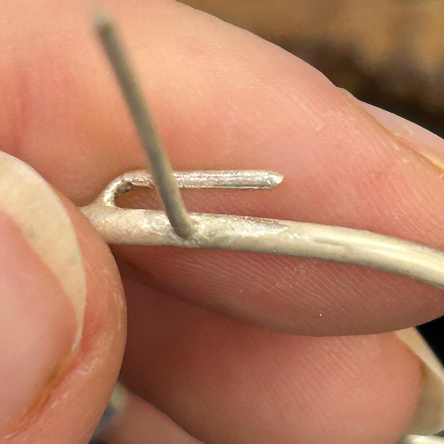
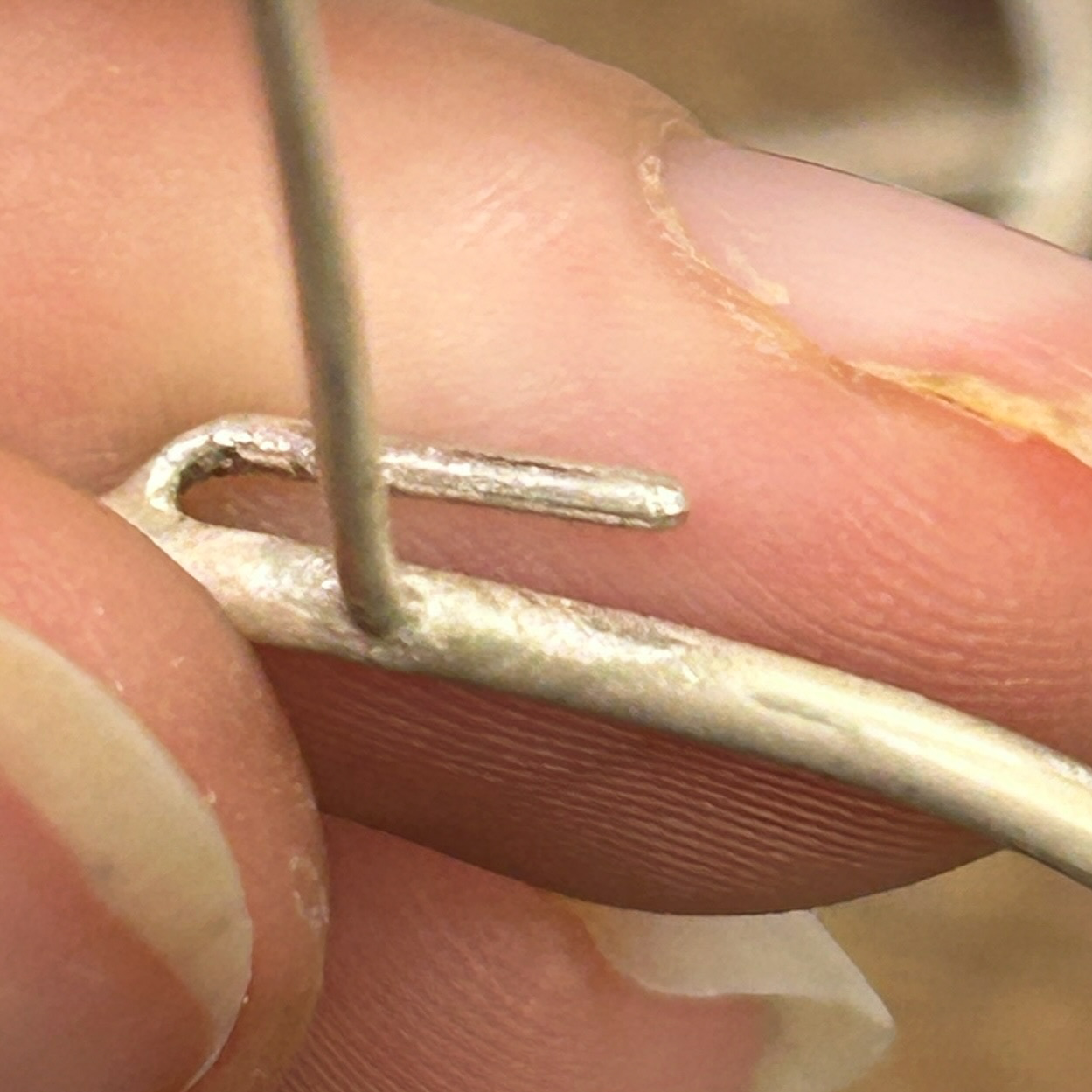
Brooch Pins
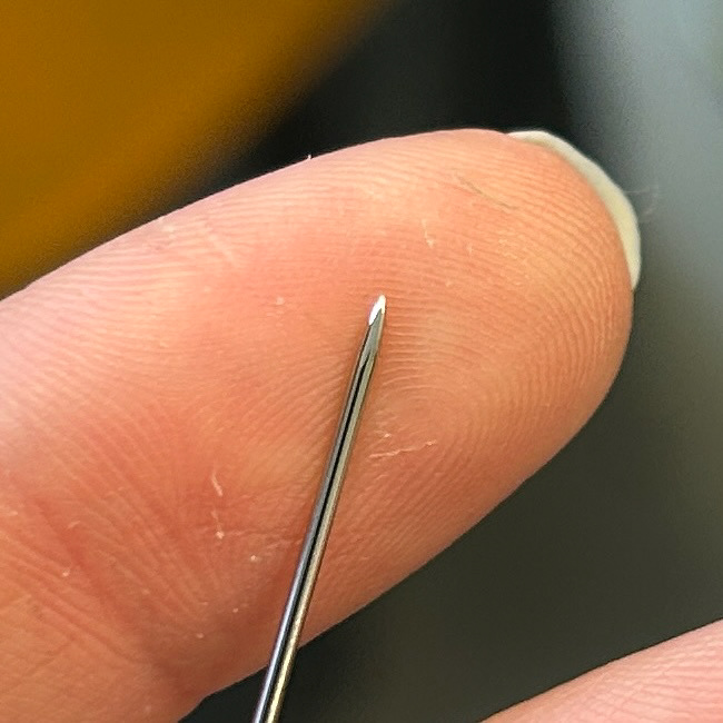
Polished pin
To make the brooch pins, I used the same steps as what Patricia had shown us during the pin workshop. This included cutting the prongs to the length where at no point when passing through the hook should the pin ever come loose, then filing the ends to a point using the carborundum grinding wheel in big metal, and finally polishing with tripoli and rouge.
Finished Outcomes
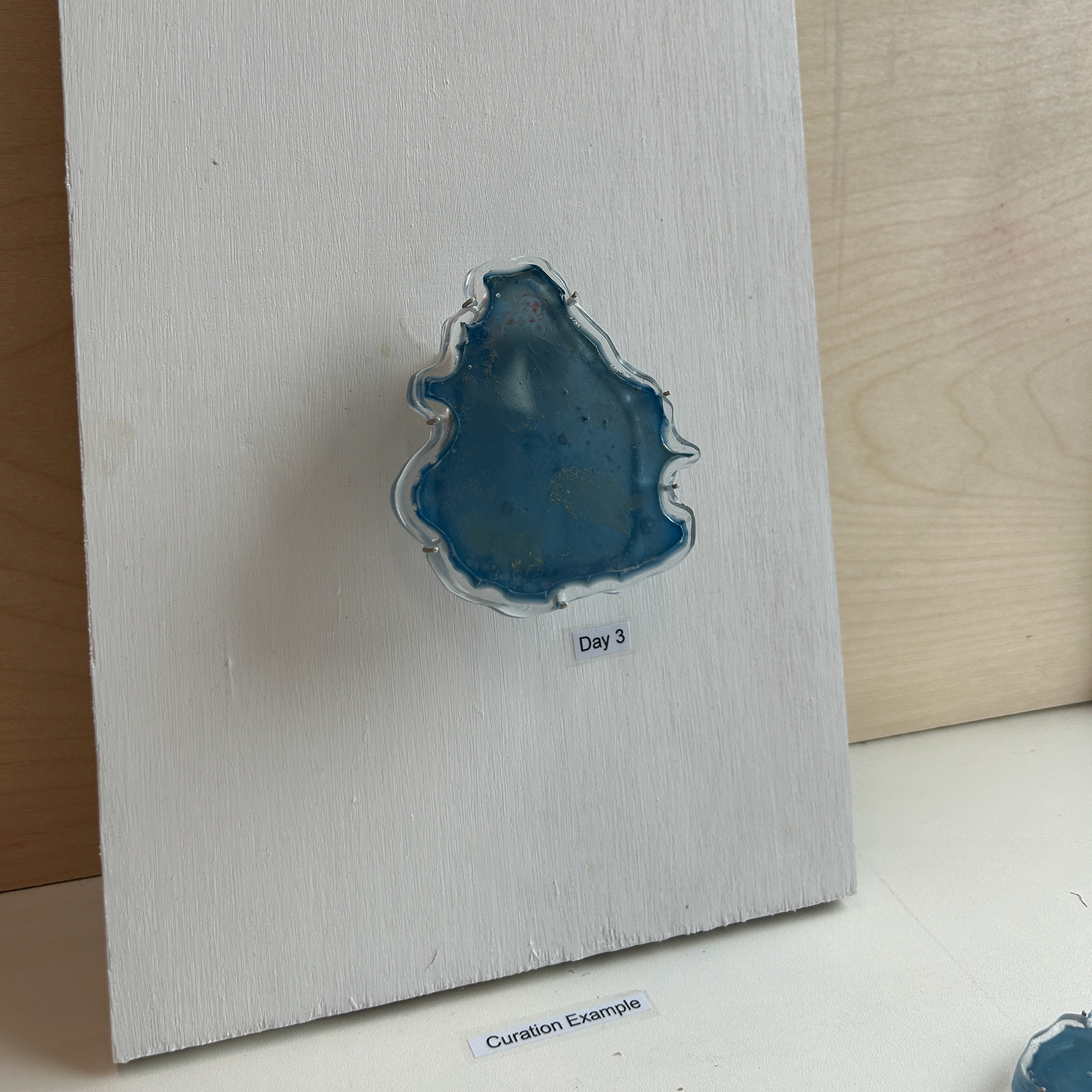
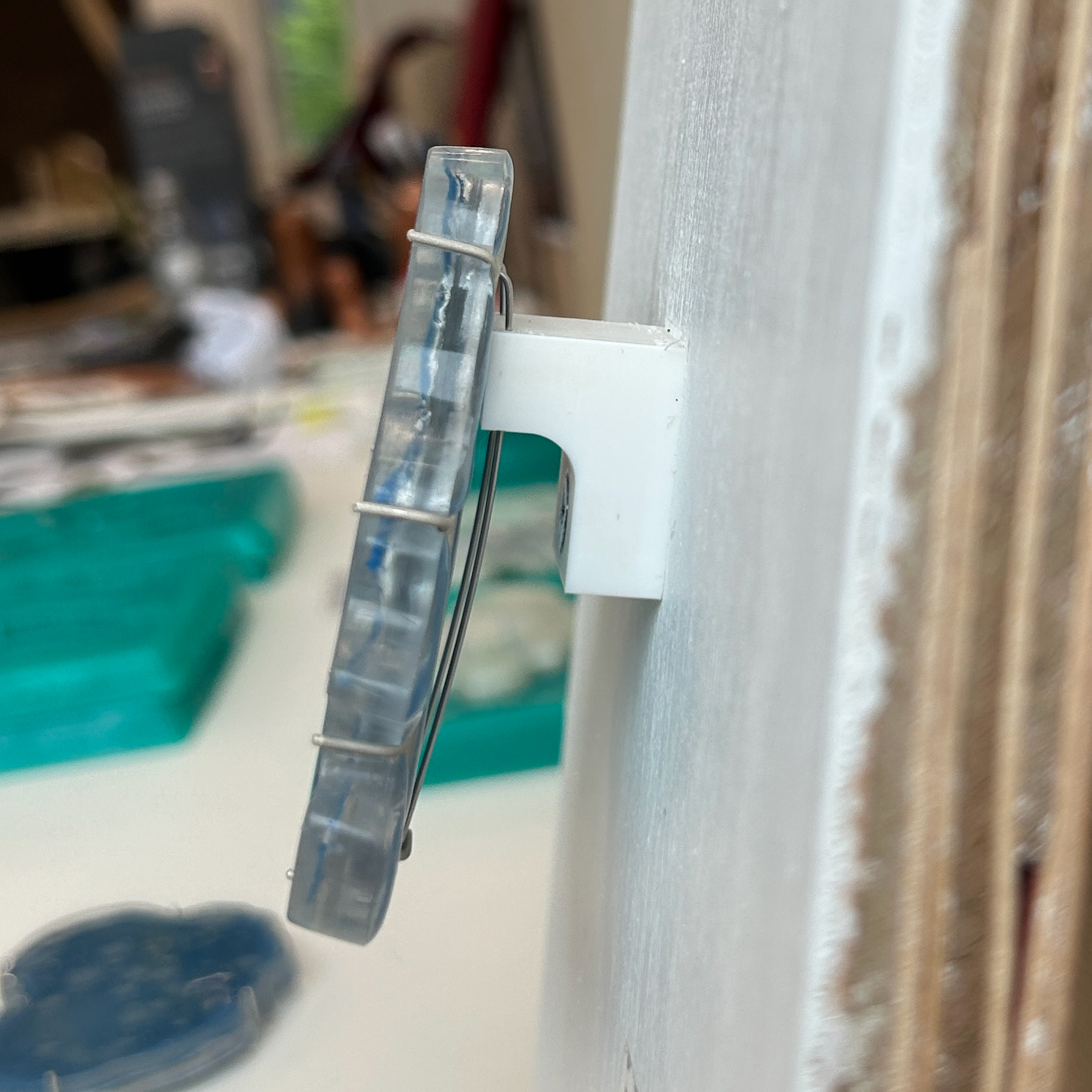
Refining the Mount
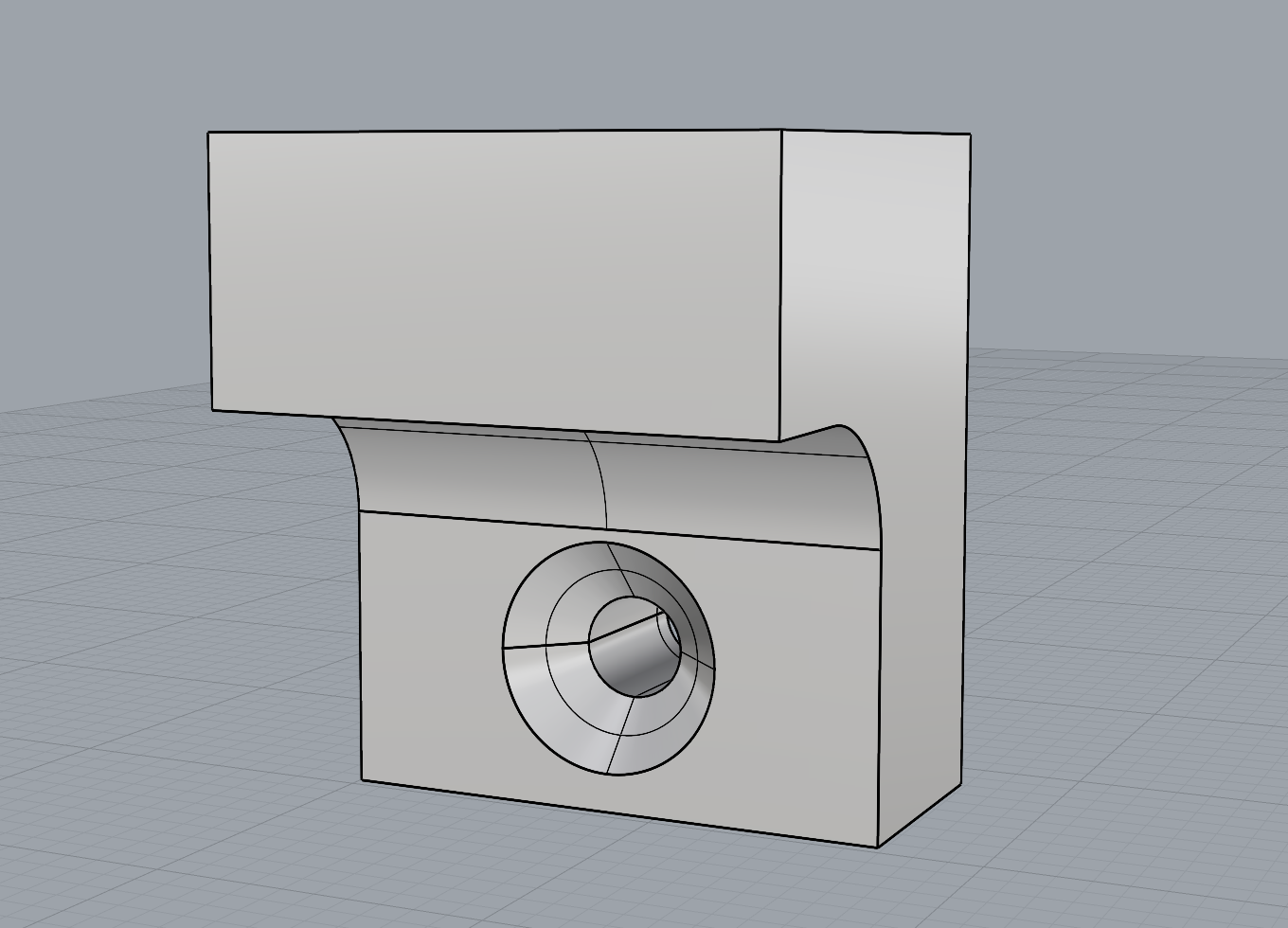
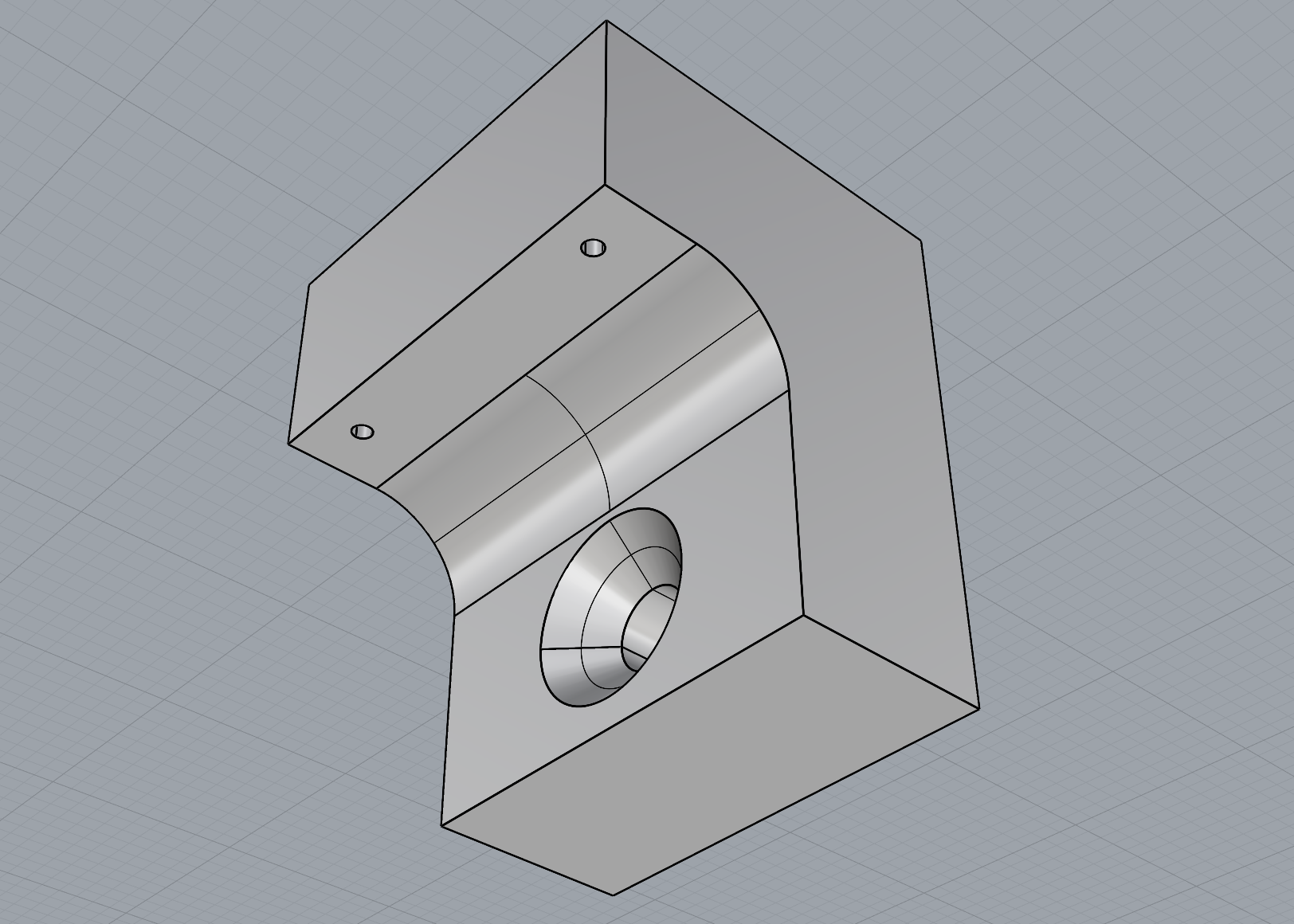
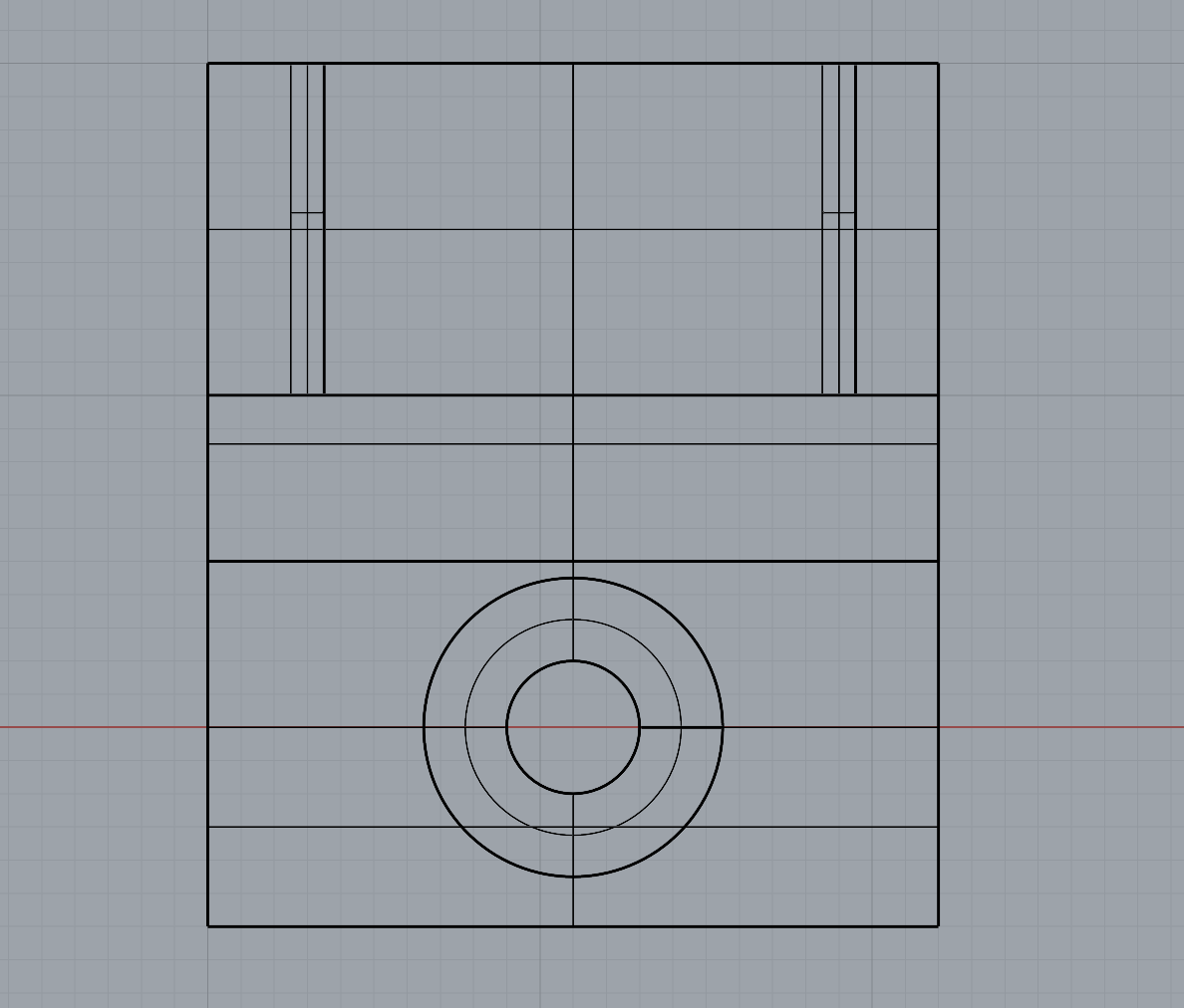
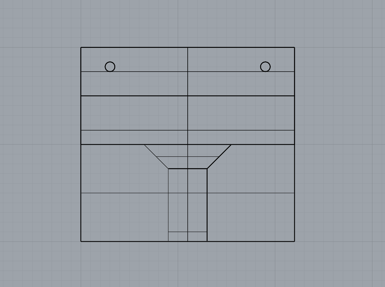
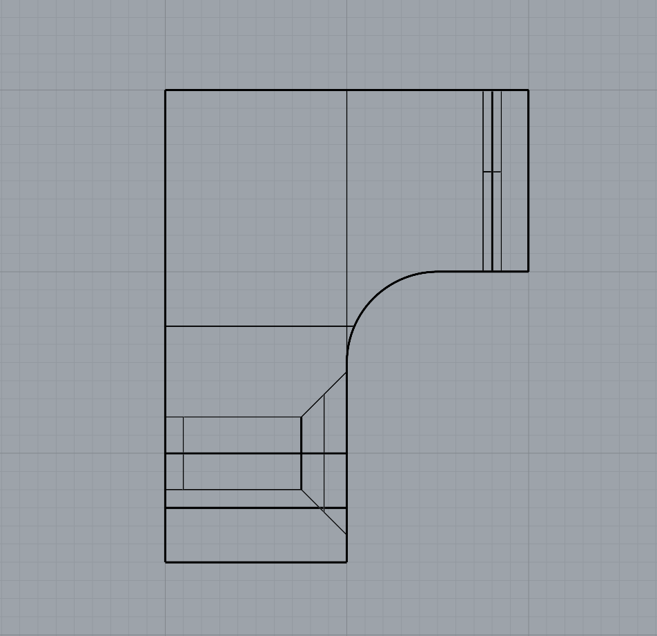
As part of refining my mounting mechanism, I realised I needed to widen the filleted edge to allow the screw to sit completely flush with the 3D print. This adjustment required increasing the height between the small shelf-like piece and the base to accommodate the 25mm chamfer. I also removed the original 1mm holes at the correct width to allow the Day 3 brooch pins to slide through smoothly.
The updated mechanism worked much more effectively than my first tests, and printing with a 0.2mm nozzle provided the level of detail I needed. I chose to print the mount in white PLA so it would blend in more with the wall.
Overall, I feel the mounting solution is successful. It gives just the right amount of space between the brooch and the wall, allowing light to pass through and showcase both the bacteria and the silver bezel backing, which was effect I was aiming for.