Silver Enamelling Tests
22nd October 2024
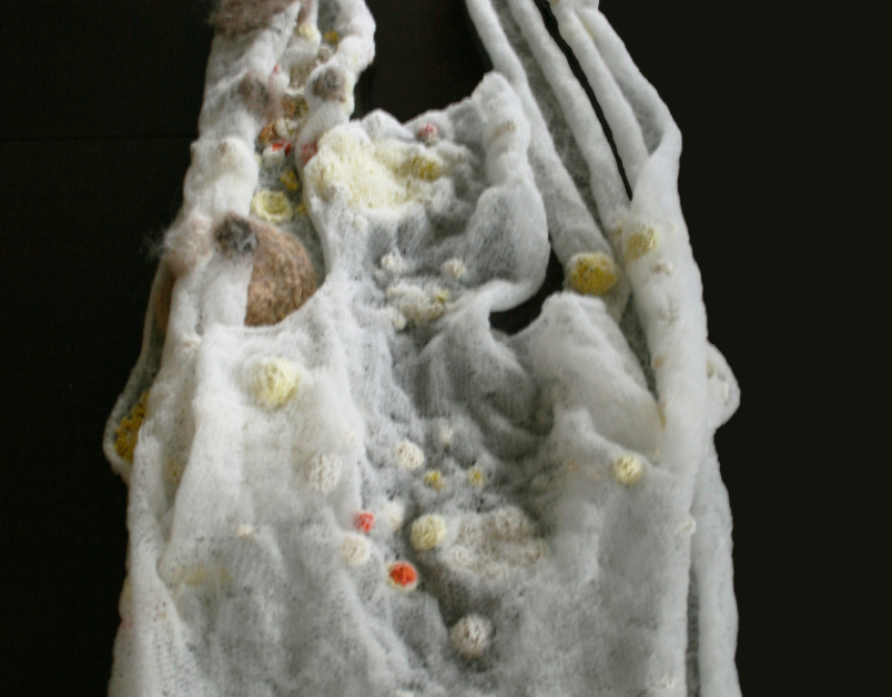
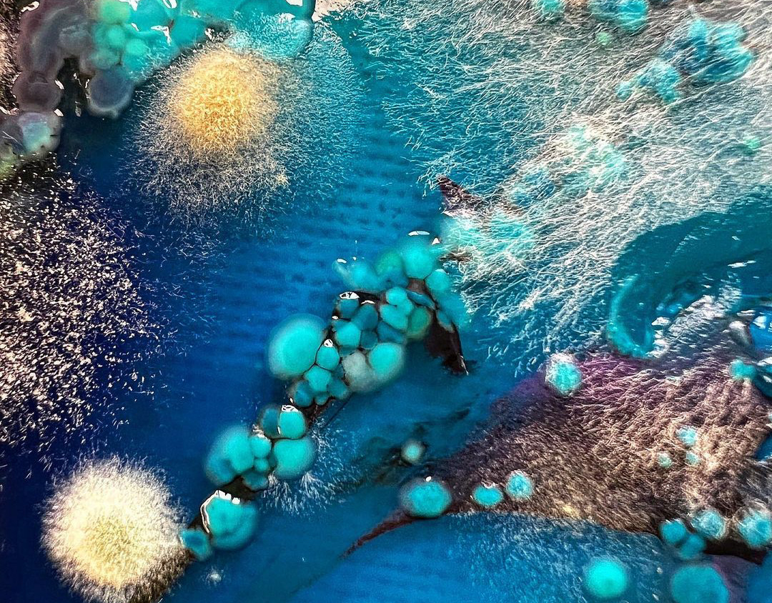
Inspired by Sinae Baik's brooches, I decided to experiment with enamelling techniques. I was particularly drawn to her use of a sifting method to create soft gradients.
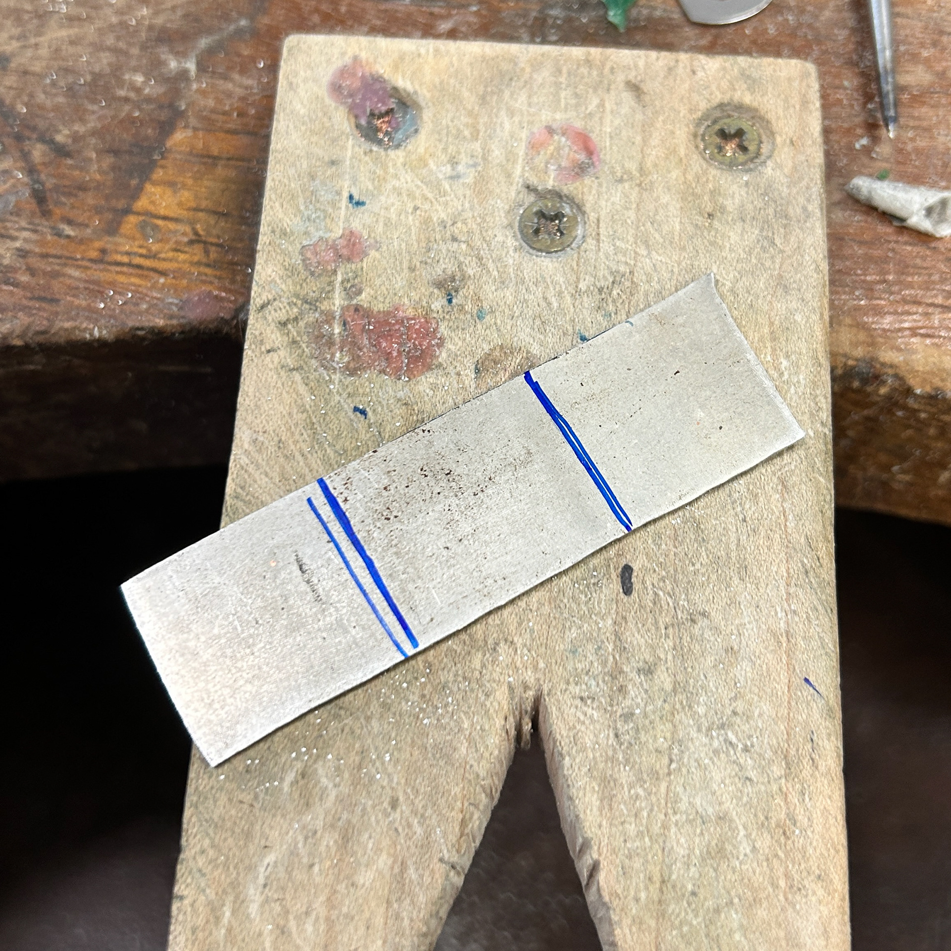
I first started with 1.5mm silver sheet, however, I decided to roll this down to 1mm so I could get slightly more material out of it. I then used a piercing saw to split it into three pieces.
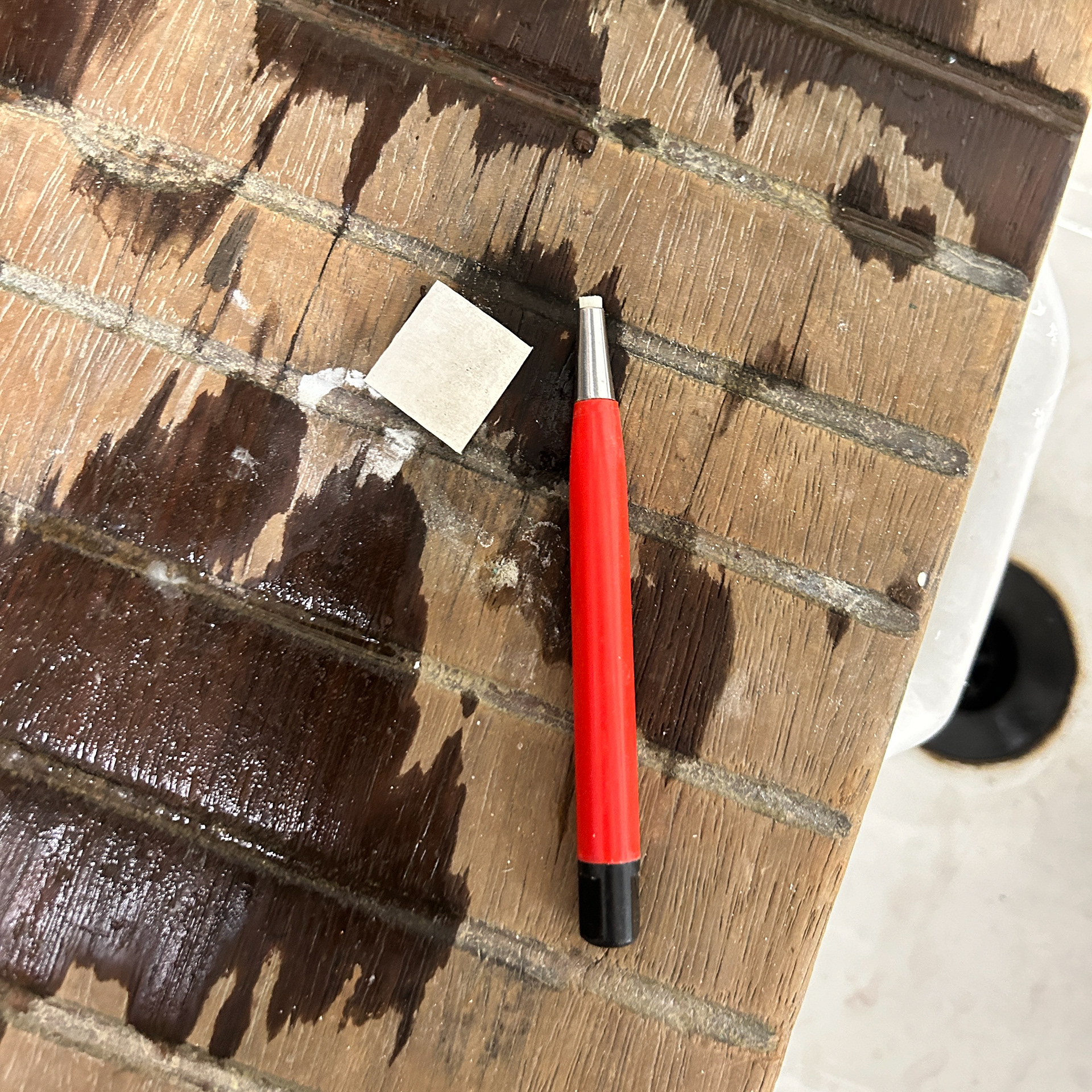
Next, I thoroughly cleaned my pieces using 1000-grit sandpaper, pumice, and a fibreglass brush, all while using gloves to ensure that no oils from my hands were left on the silver.
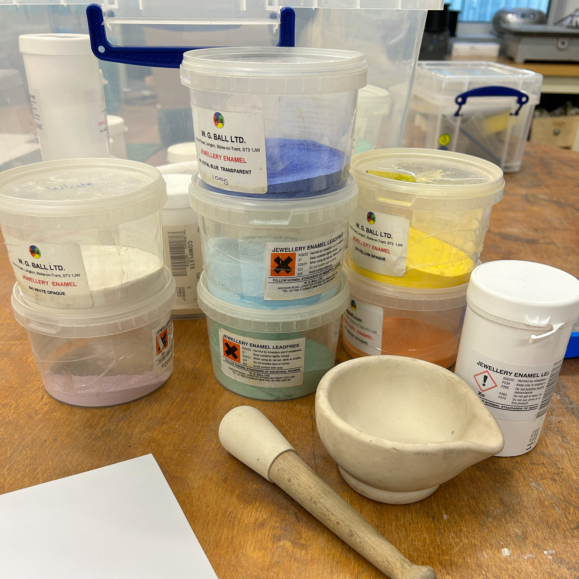
I then picked out a series of different colours to experiment with gradients. I decided to use white and purple one, orange and yellow on another, and finally three different blues on the last one.
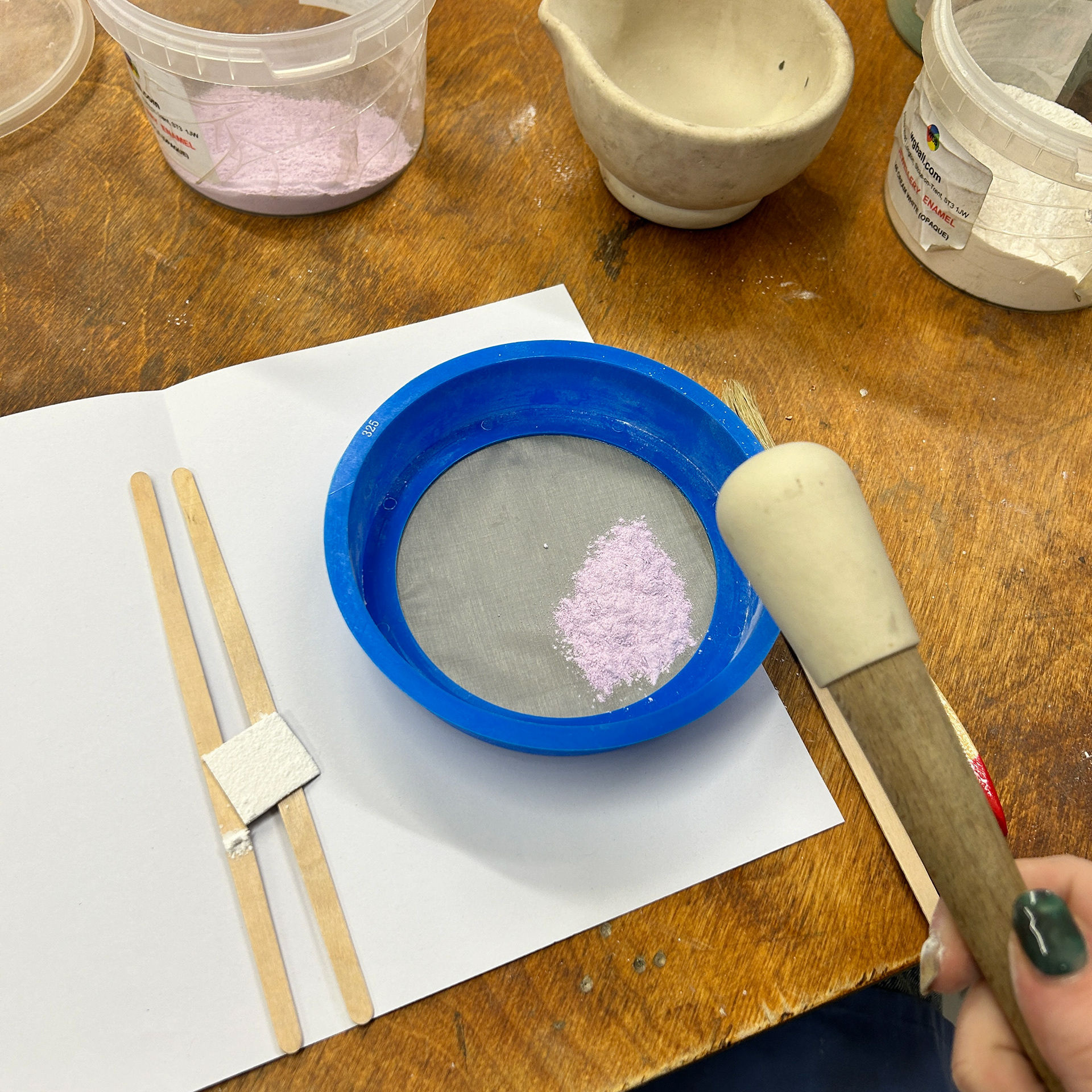
To create a soft gradient effect, I used the smallest sieve in the workshop, 325 mesh, and a mortar and pestle to make the enamel powder even finer.
I then used the pestle to help gently grind the powder through the sieve and onto the silver. I repeated these steps with all the different colours, making sure to try and make the layer and gradient as even as possible.
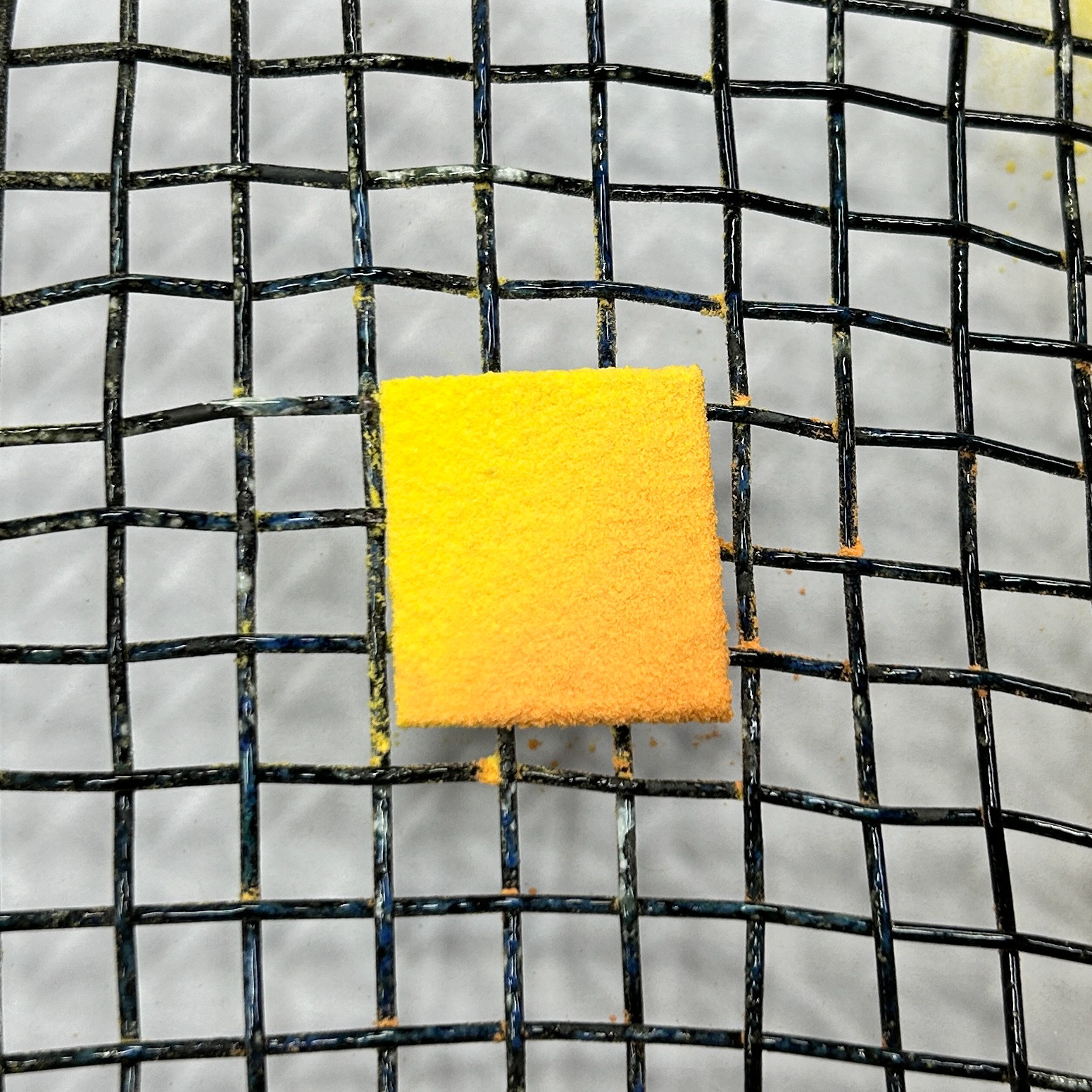
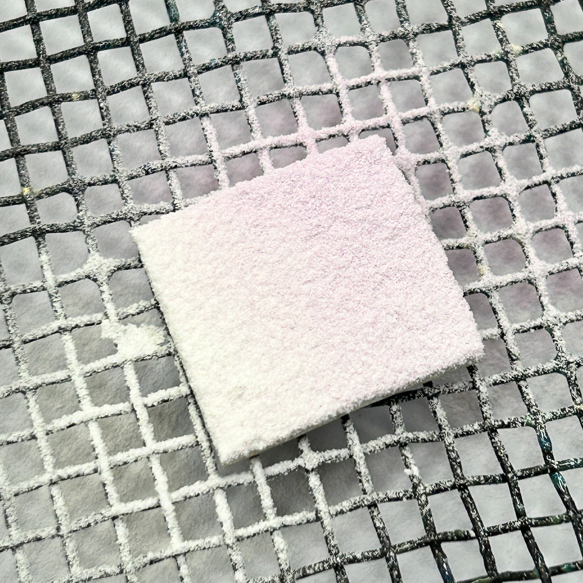
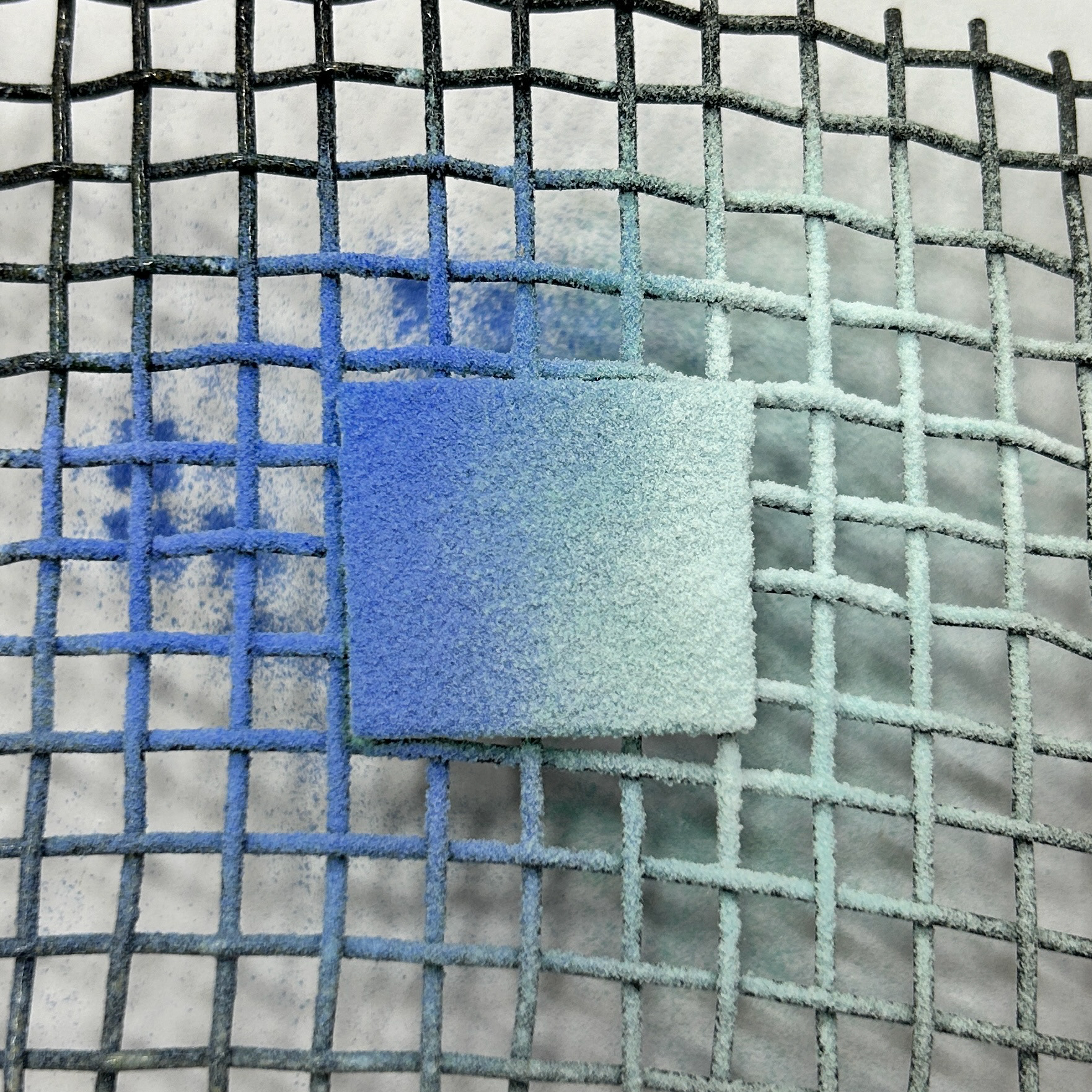
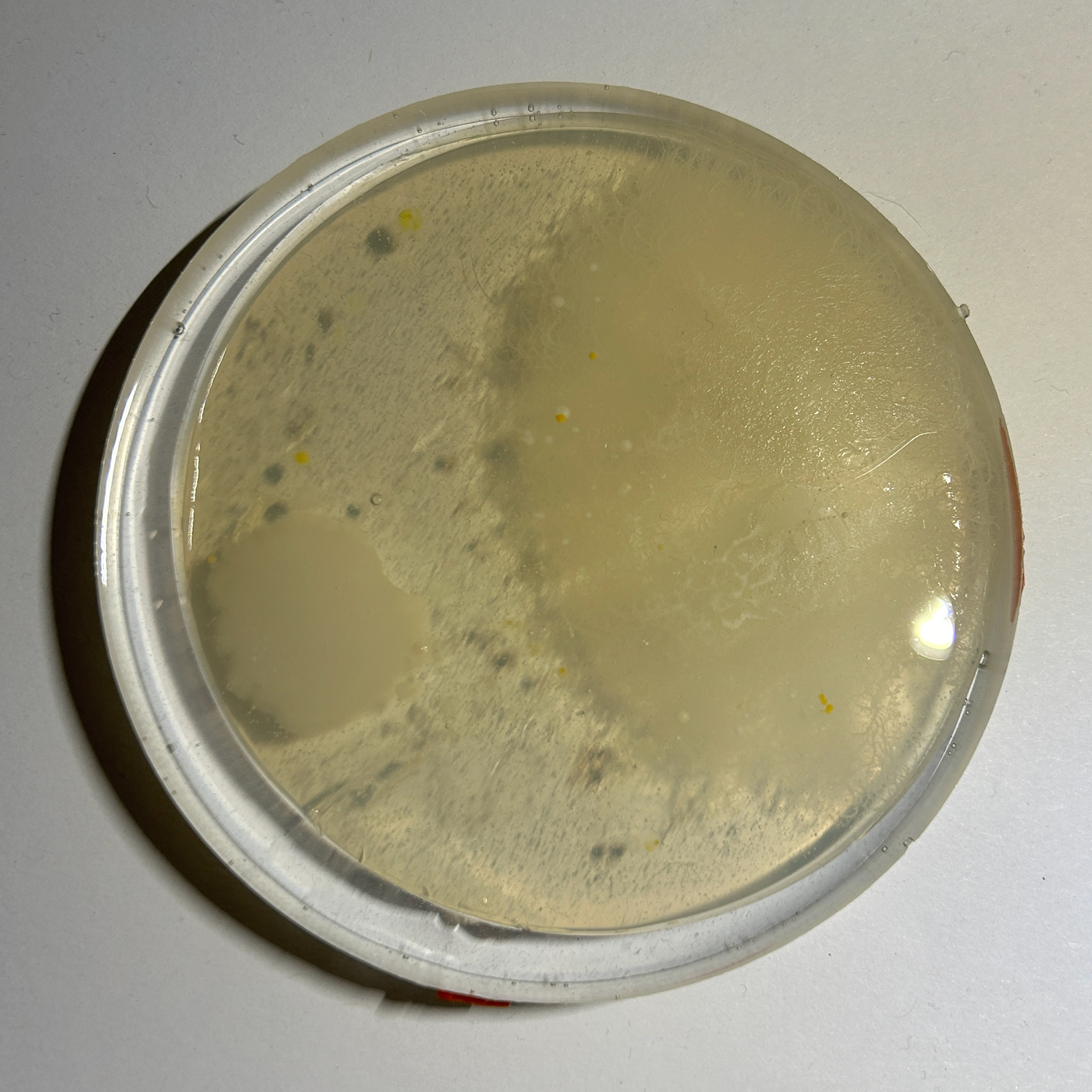
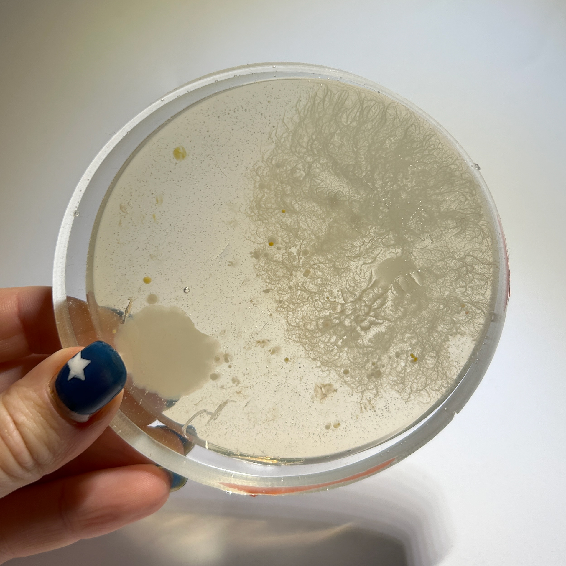
These were my samples before firing
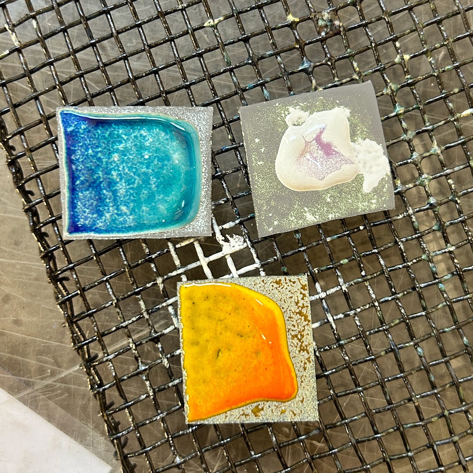
Unfortunately, the enamelling process didn’t go as planned. None of the enamels turned out correctly, which was unexpected, as I followed all the necessary preparation steps. I’ve never encountered this issue before with this method.
I had also ruled out the possibility of polish residue interfering, as I hadn’t polished the silver prior to cleaning and applying the enamel. Initially, I wondered if I might have left the samples in the kiln too long, but my stopwatch showed that each piece was only in for about 20-25 seconds.
This was even more puzzling, as the reaction appeared as if the samples had been over-fired, which didn’t align with the timing. I’ve used these enamels before and know they typically take 30-40 seconds to achieve the correct finish.
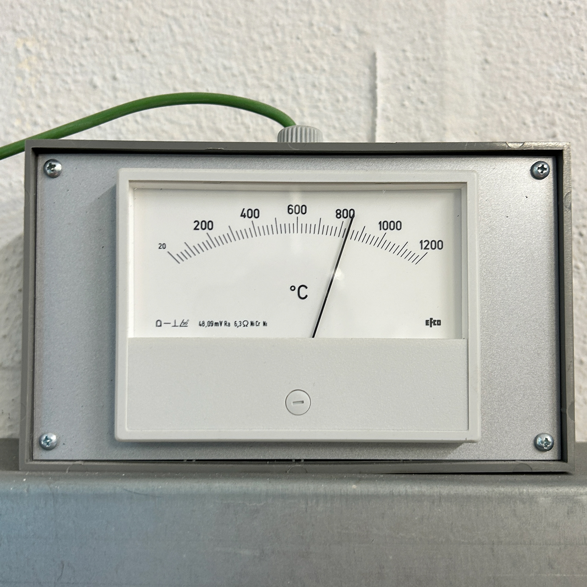
I also decided to check the temperature of the kiln as I have previously found that these enamels work best between 820°c-860°c, after looking back at the temperature the kiln was holding, I found that it was approximately 830°c, which would not be high enough for it to melt the enamel like this.
I spoke to Maisie, Paul, and Mark about this to see if any of them had any idea about why the enamel reacted like this.
Pauls only suggestion was to maybe add more enamel on the outside edge of the sample, but was not too sure if that would be the cause of this.
Maisie suggested that maybe the different types of enamels could be hard and soft enamels, where the melting temperatures are different, however after I explained that I have used all of these before with wet enamelling techniques last year, then we ruled that out as well.
My only thought was that maybe rolling the silver thinner, it made the silver heat up quicker and unevenly, which would explain why the enamel pulled to the middle. From now on I will enamel any silver in 1.5mm thickness as I have the most success with this thickness.
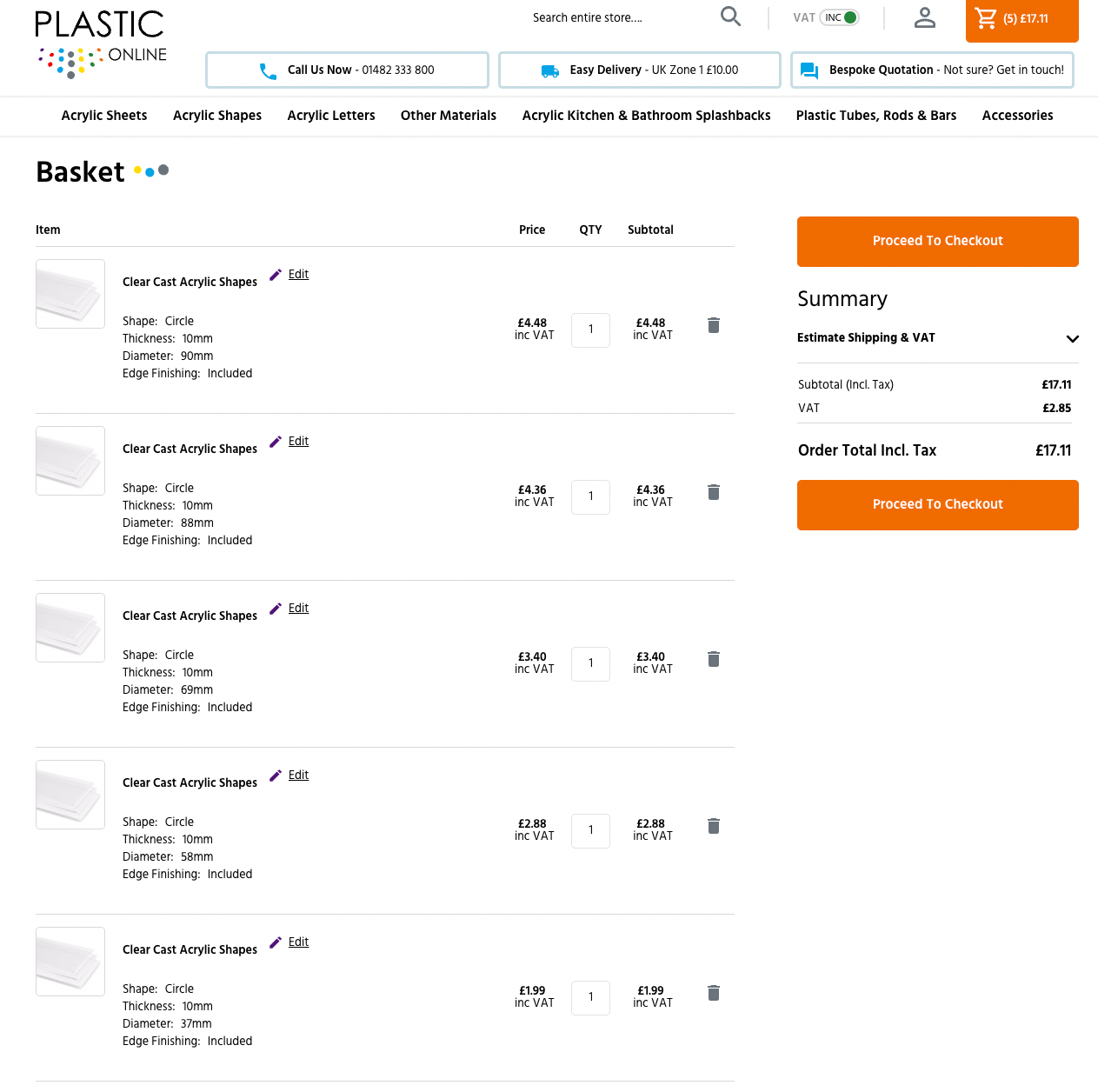
Wax Experiment
24th October 2024
After my tutorial with Geoff, I decided to experiment with a potential setting for one of the petri-dishes
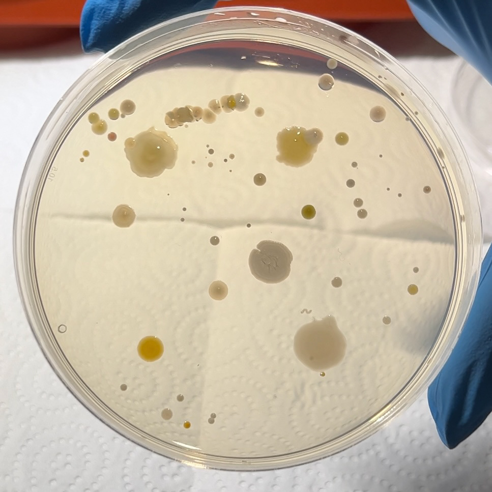
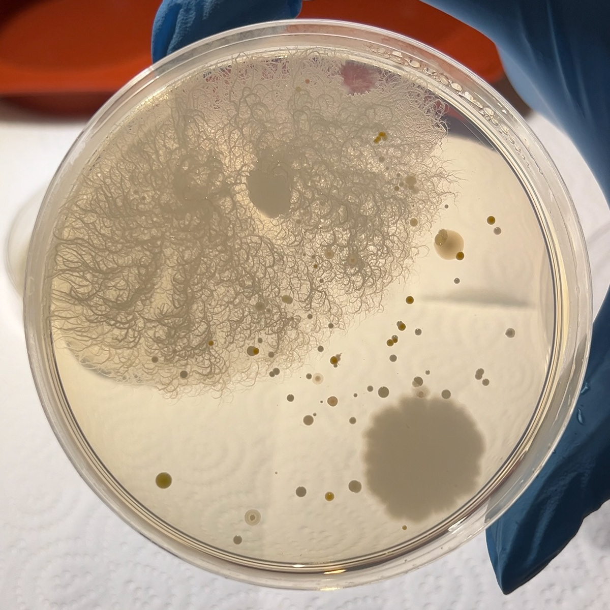
I decided not to 100% plan this piece after speaking to different makers at Great Northern. Jennie Gill suggested that I take a more experimental approach to my work and not limit myself to a particular design. Because I felt intimidated by this idea, I decided to use the pictures of my bacteria samples as a source of references.
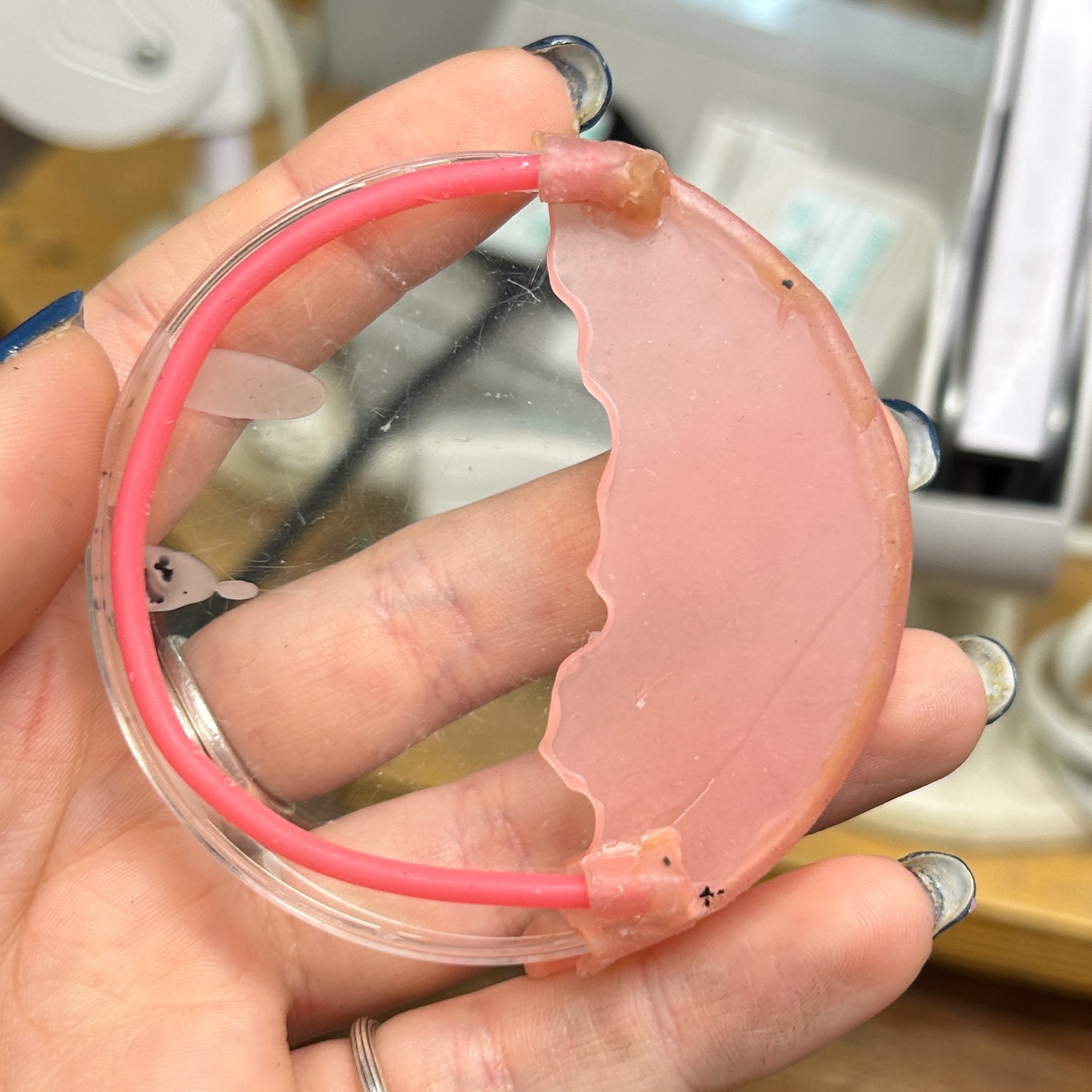
I decided to try and make a semi-bezel wax cast, that would be able to hold the petri-dish, while also allowing much more light into the dish than a traditional bezel. I decided to use the shapes and patterns I had seen in the Petri dishes to help inspire the shapes I was creating.
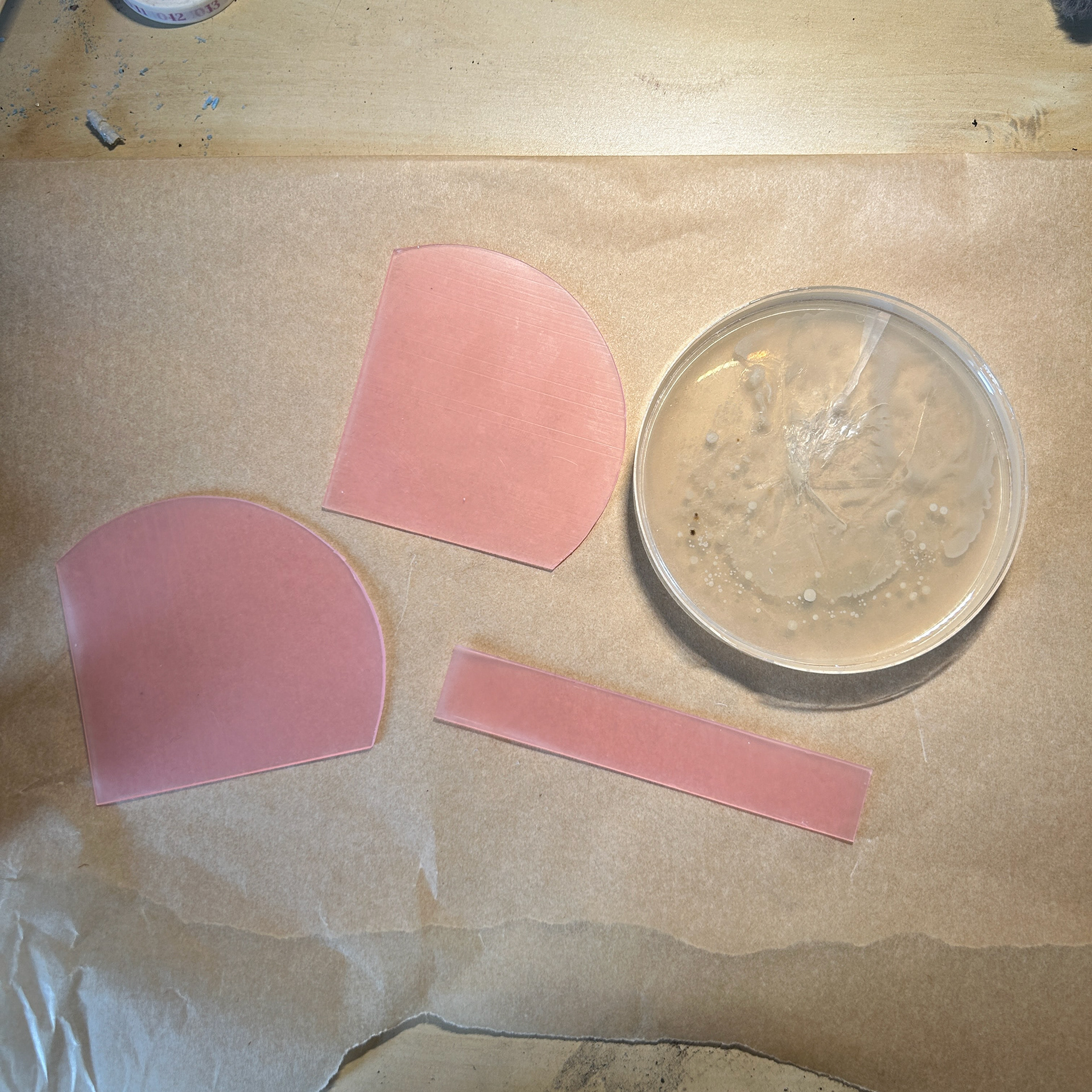
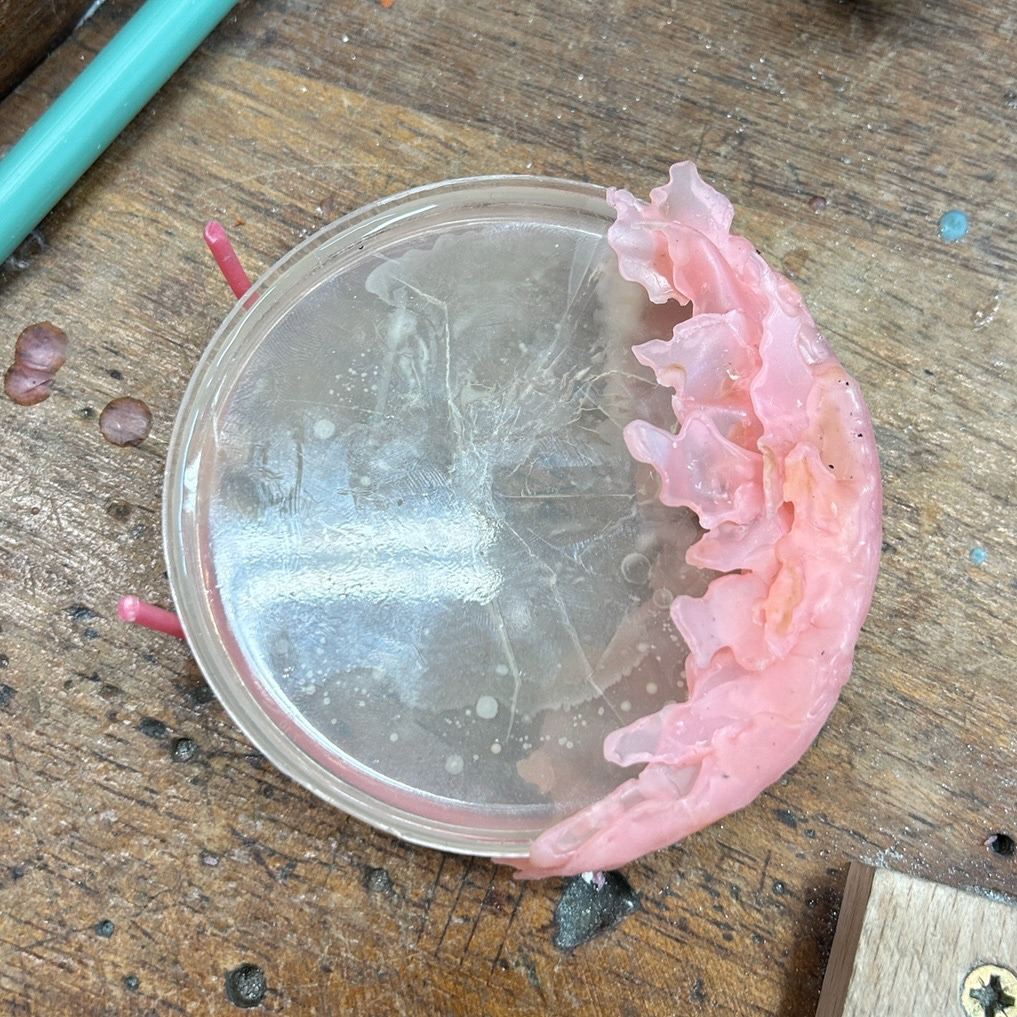
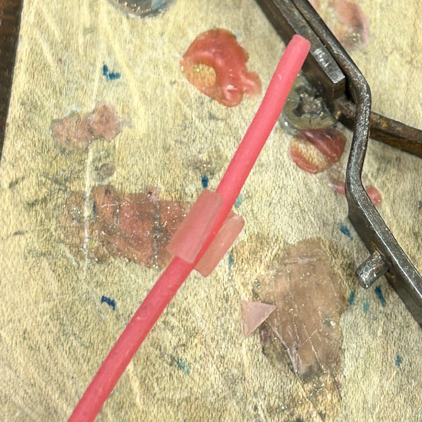
To make this, I used pink wax sheets, which are more flexible than the blue Ferris wax I usually work with. This flexibility allowed me to wrap the bezel into the correct shape to support and secure the dish.
I used my soldering iron to create a rough outline inspired by the boundaries of some of the colonies I had previously grown. With a slightly larger backing to allow for a potential brooch mechanism.
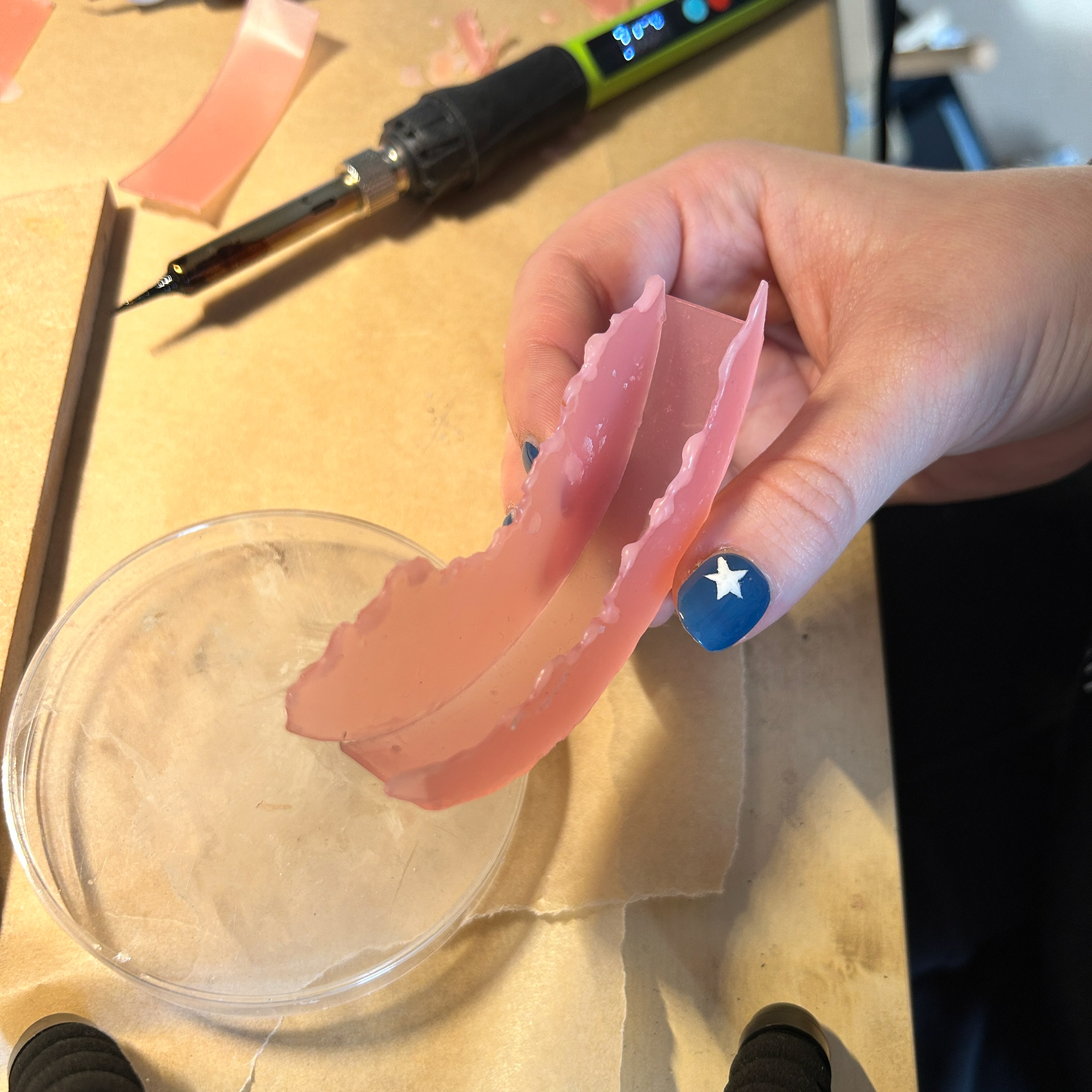
I also decided to test a new technique to curl the wax sheets as I wanted more depth in this sample. I used the end of a paintbrush and a sponge to help me form these shapes, inspired by a technique I have used for fondant icing while baking. I feel as if this worked quite well however, I feel as if using a large dotting tool or a silicone tool may have worked better, as the paintbrush was quite hard to manoeuvre over the wax. These shapes were also inspired by the shapes of the bacterial colonies I have grown.
Next, I experimented with layering the wax pieces to create additional depth and visual interest, aiming for an effect where the wax appears to peel away from the bacteria. This approach could be especially effective in brass, as brass is naturally antimicrobial, giving the impression that it’s being repelled by the bacteria rather than the other way around.
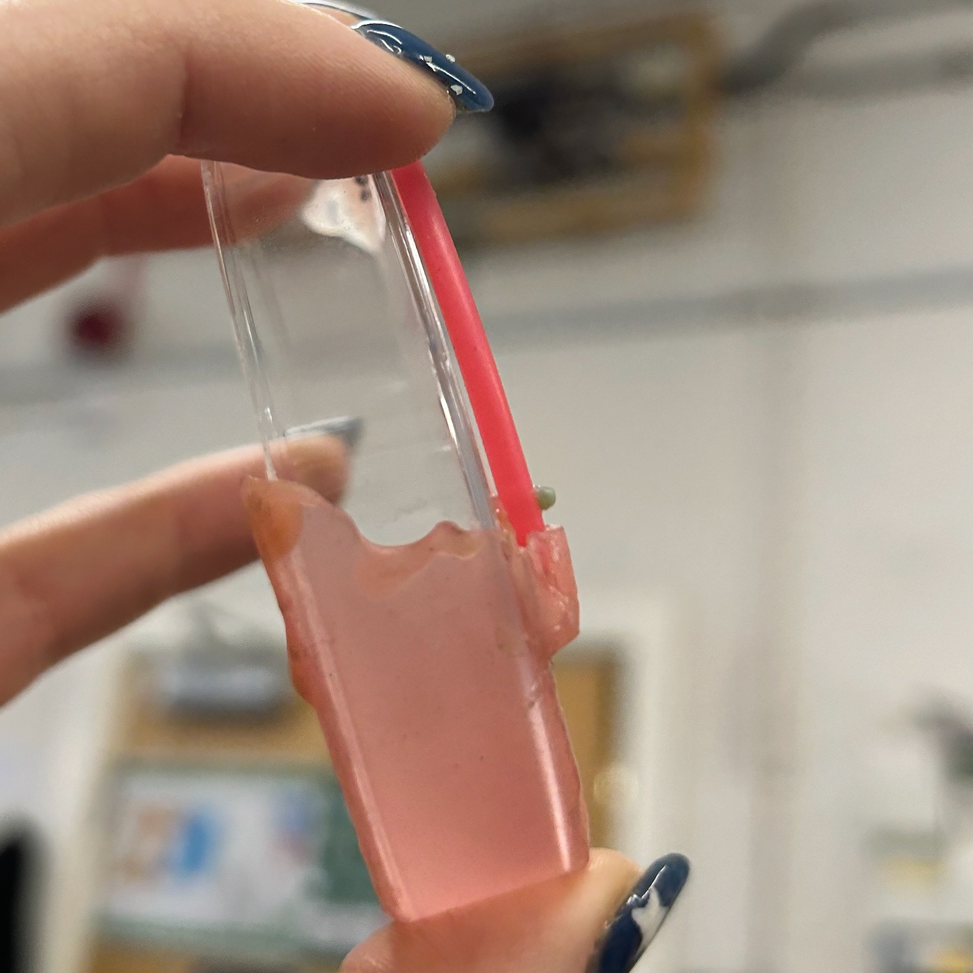
This video shows the process of how i connected the front, back, and side pieces using my wax pen.
While this was very time-consuming, I have learnt from past mistakes where I have used a soldering iron to join two pieces of pink wax. As mentioned before, pink wax is much softer and therefore has a lower melting point. I believe that if I was to use a soldering iron for this, I would have melted the pieces too much and left gaps around the edge, resulting in more work for me.
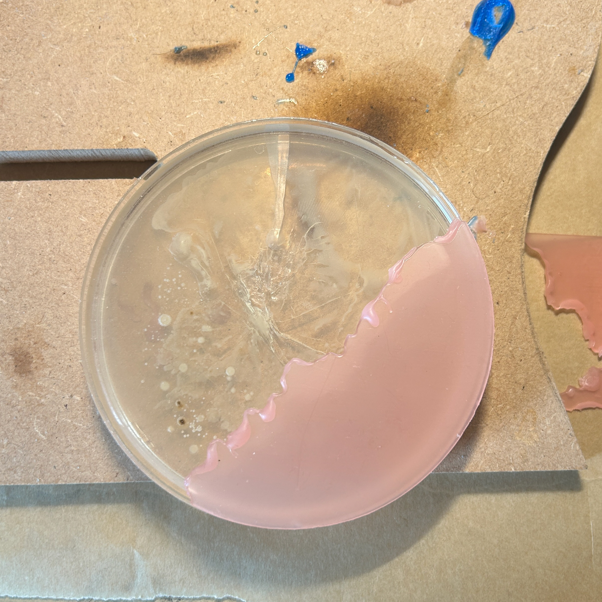
I used a previously made petri dish to help support my sample while I was connecting the pieces together, to reduce the risk of making the setting too tight to fit a petri dish.
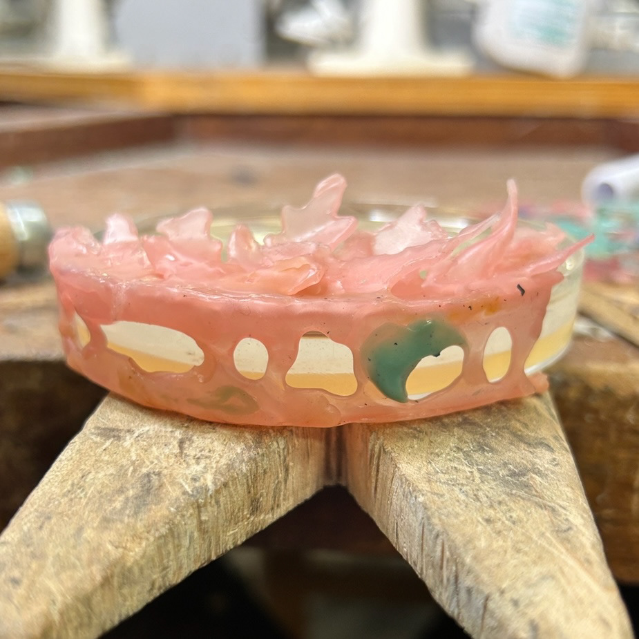
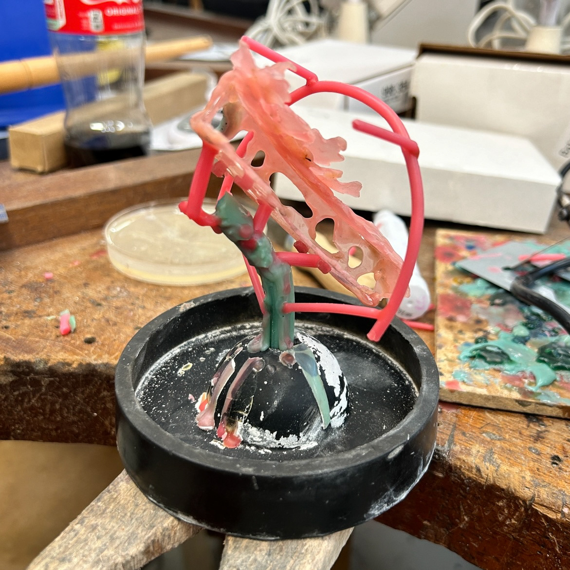
I then added a bezel and prongs to support the dish from the back, along with a brooch mechanism I previously used in UC2. This mechanism is particularly effective for heavier brooches, as it allows me to customise the spacing between the pins, covering a larger surface area for better stability. I also incorporated open spaces on the side of the brooch, enabling the wearer to view the bacteria from different angles and adding visual interest.
These openings also help reduce the overall weight of the piece, making the casting process more efficient and cost-effective.
The mechanism for inserting the samples is straightforward: the prongs can be gently bent away from the brooch, allowing the sample to slide in, and then pressed back to secure the dish in place.
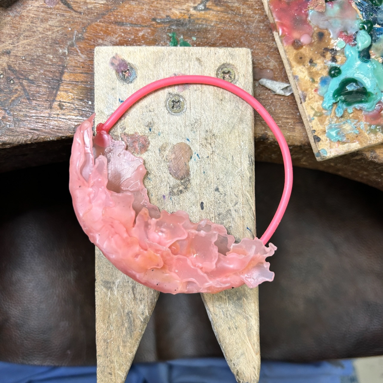
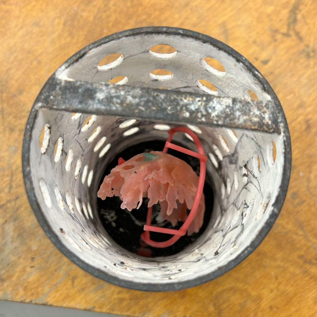
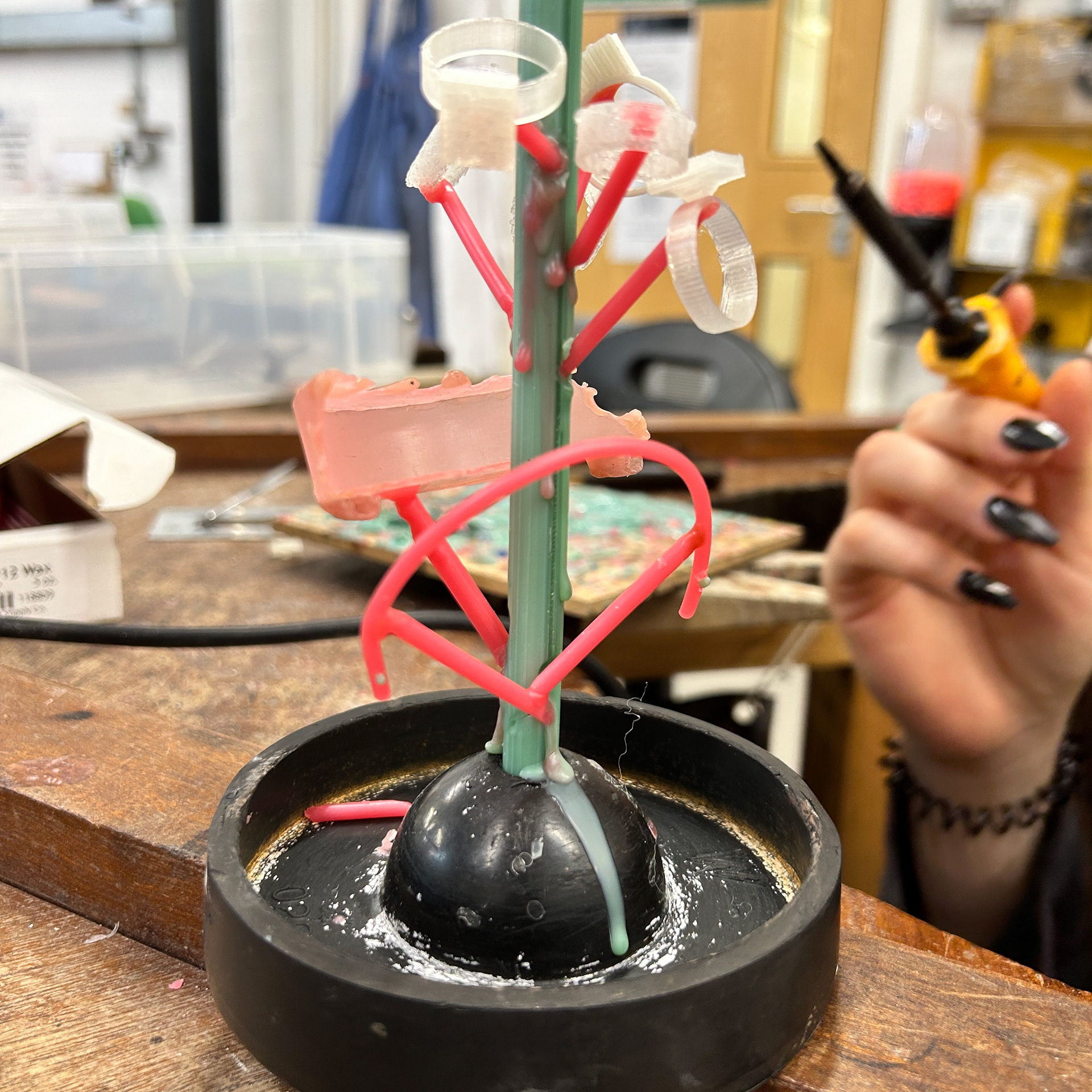
However, when testing the wax model against the casting crucible, I realised it was too large to fit, especially considering the need for at least a 2 cm clearance around the cast for the plaster to properly support it during casting.
To resolve this issue, I melted off the circular bezel and attached it separately to the wax tree. I plan to solder it back onto the main piece after casting.
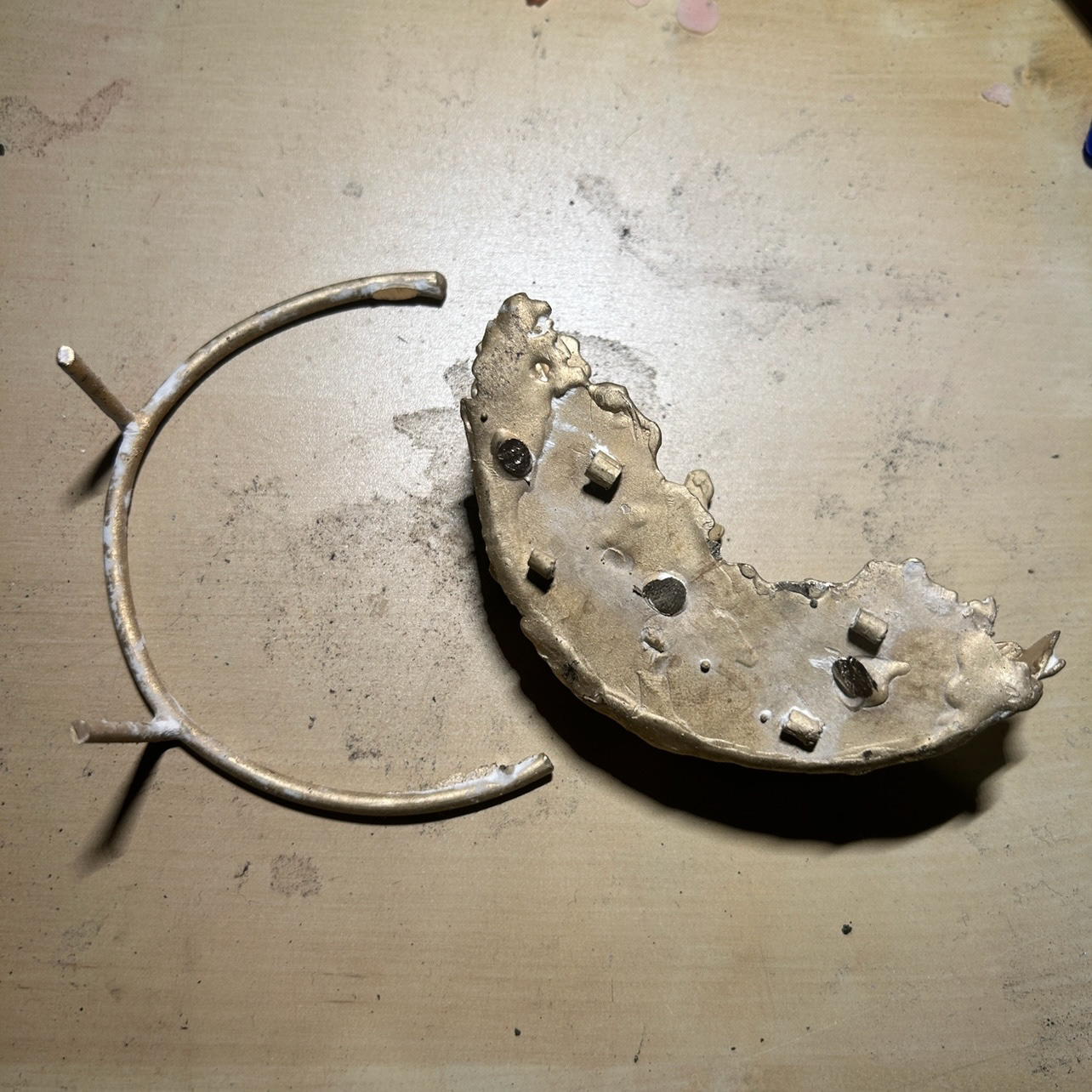
Casting
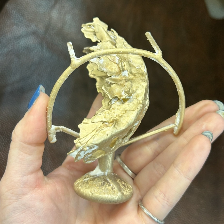
While working on this piece, I quickly realised that I did not enjoy working at this larger scale. My work typically involves smaller, more delicate pieces, and although I wanted to experiment with scale, I found it was not an enjoyable process for me.
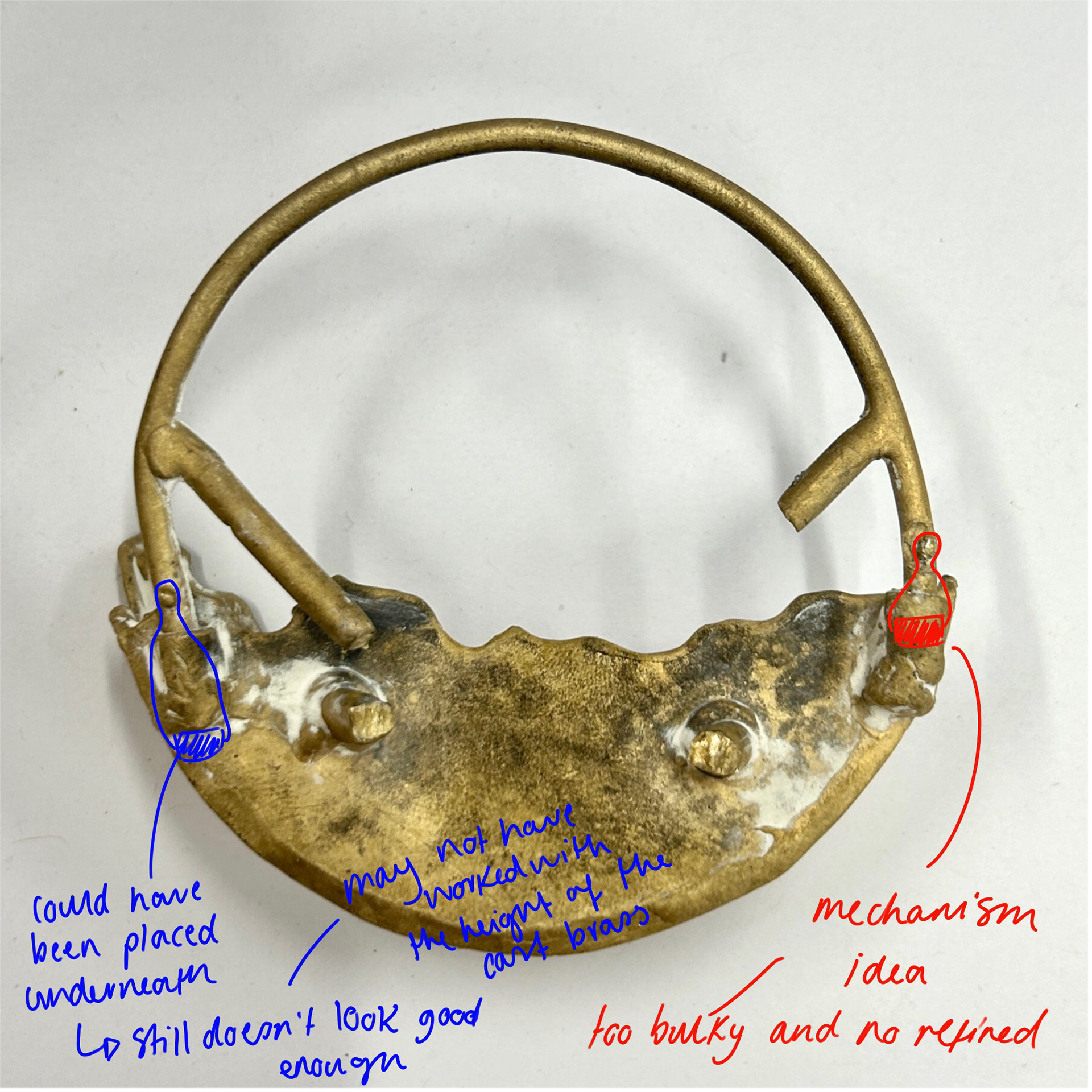
The mechanism also did not function as intended. The prongs were much too rigid to bend as easily as I had hoped. In hindsight, I should have expected this issue, as I’ve had prior experience with cast prongs and know how challenging they can be to manoeuvre into place.
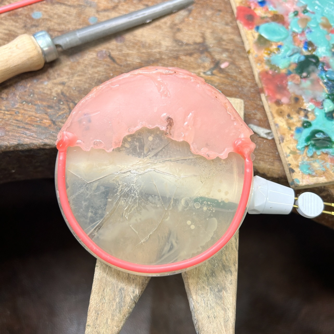
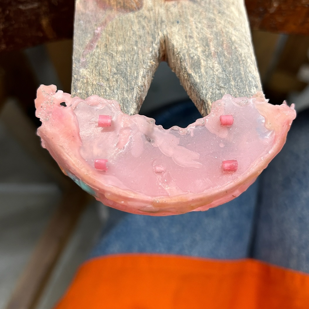
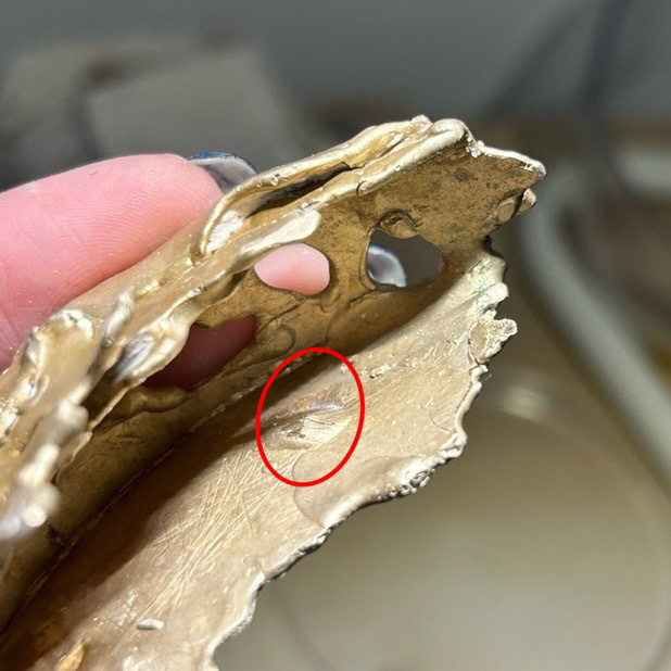
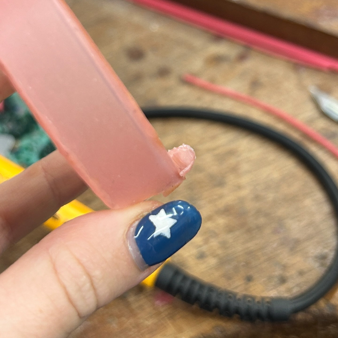
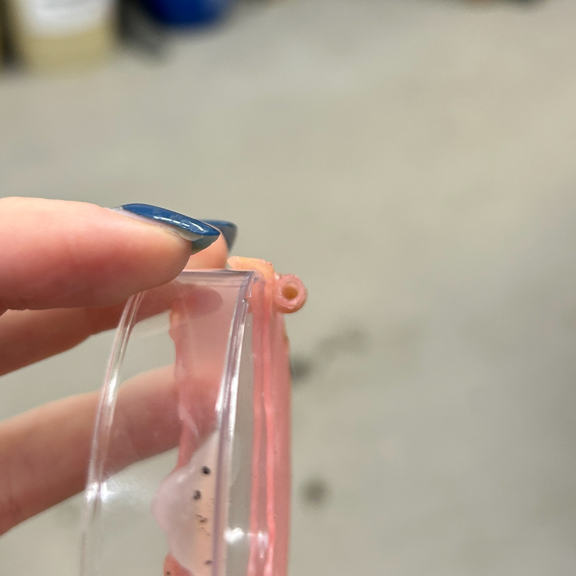
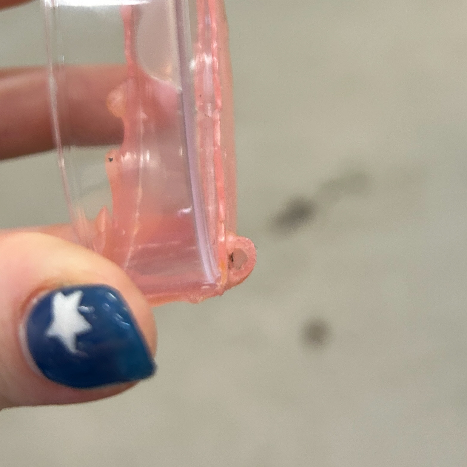
Additionally, the pink wax left visible marks where I attached the sprues, which I’ve circled in picture 5. I did not like this at all, as it gave the piece an unrefined and unprofessional appearance. The marks were also difficult to file down because they were so close to the enclosed edge of the cast. The soldering, too, looked messy and lacked the clean finish I wanted.
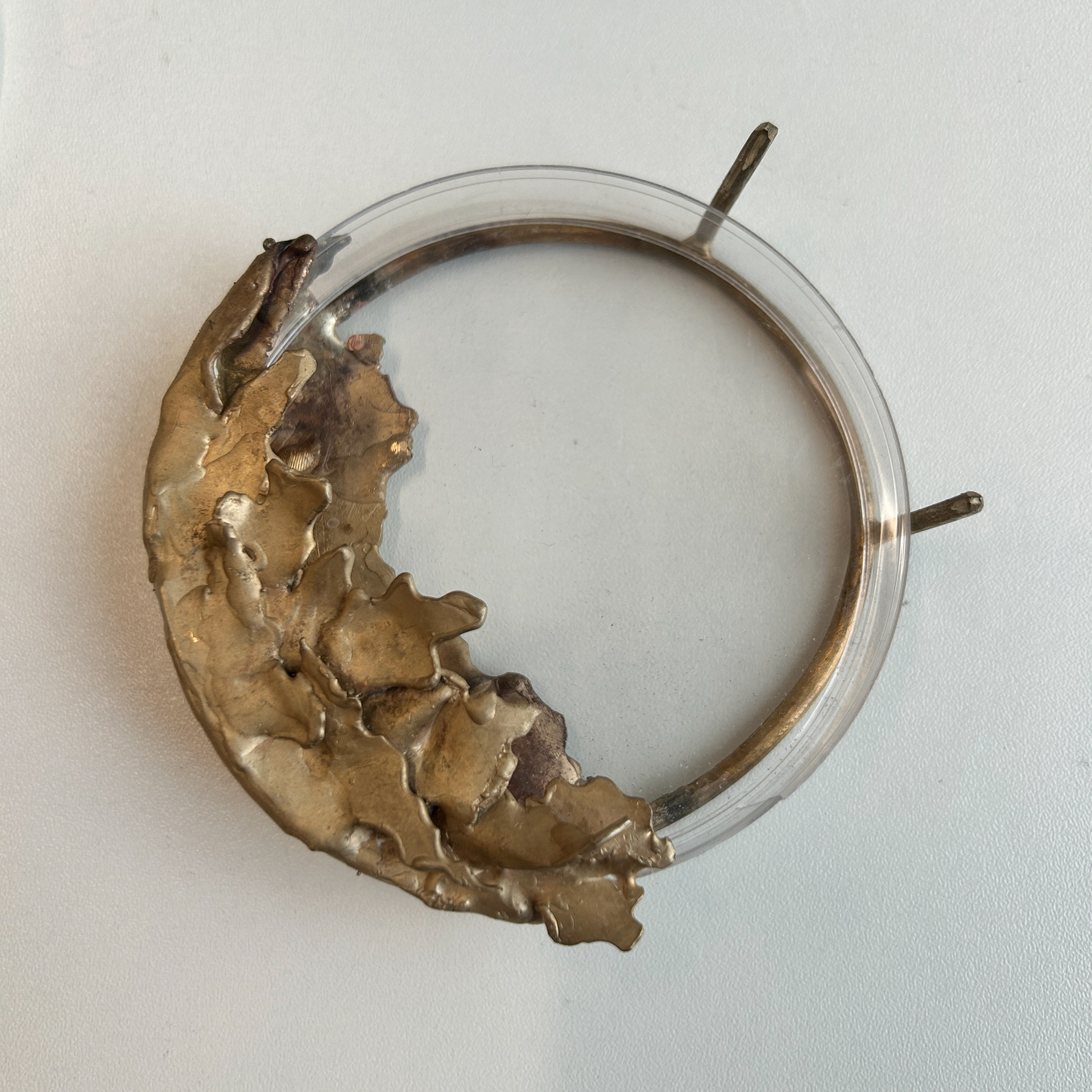
When testing the brooch with a sample, I used an empty petri dish without agar. However, I had to bend the plastic to fit it into the space, causing the sample to crack, making it unsuitable for holding my bacterial samples.
Gel Flex Mould Making
31st October 2024
After my formative review, Geoff suggested finding a way to remove the agar from the petri dishes. This would make the pieces less bulky and easier to work with.
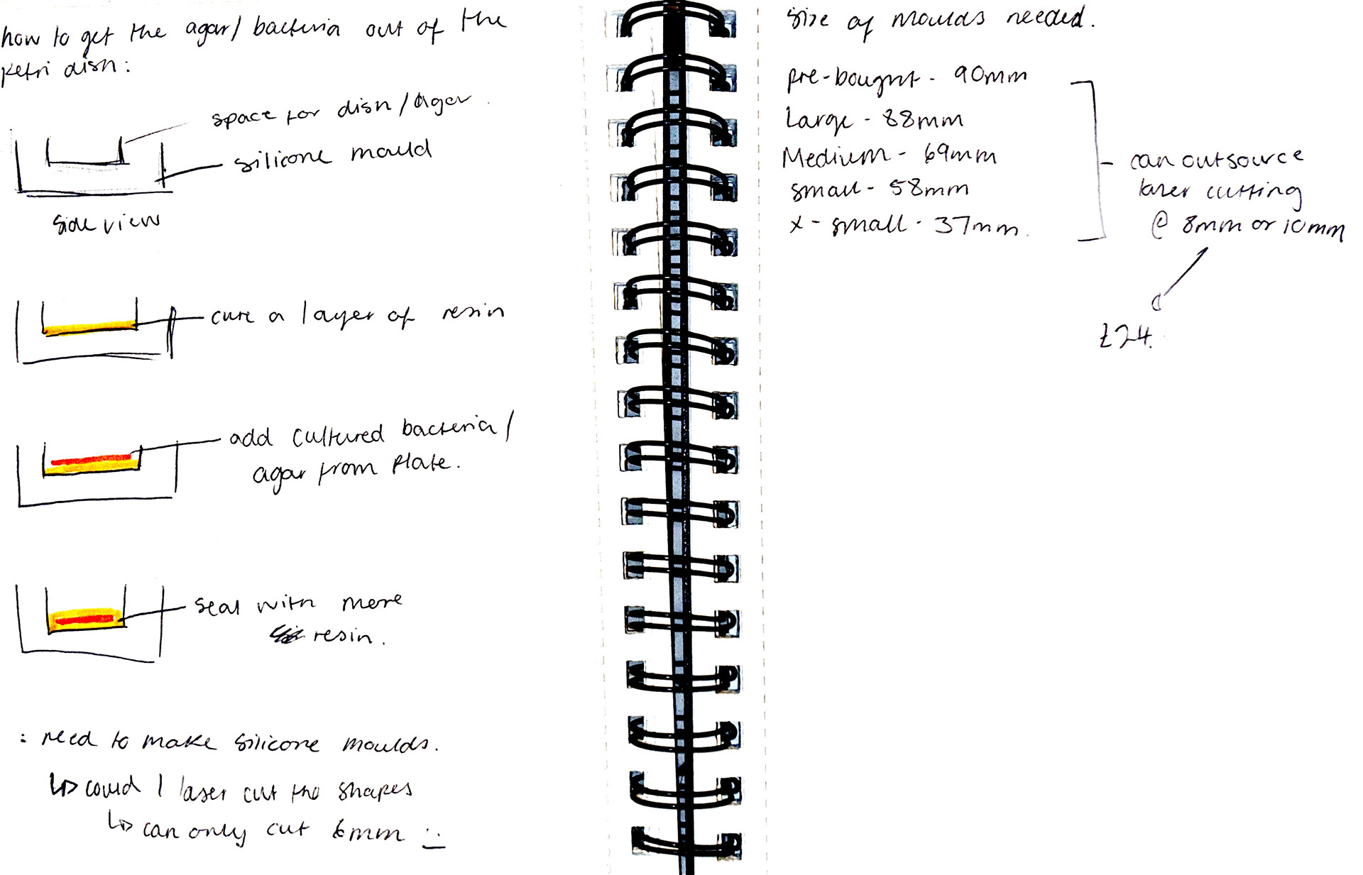
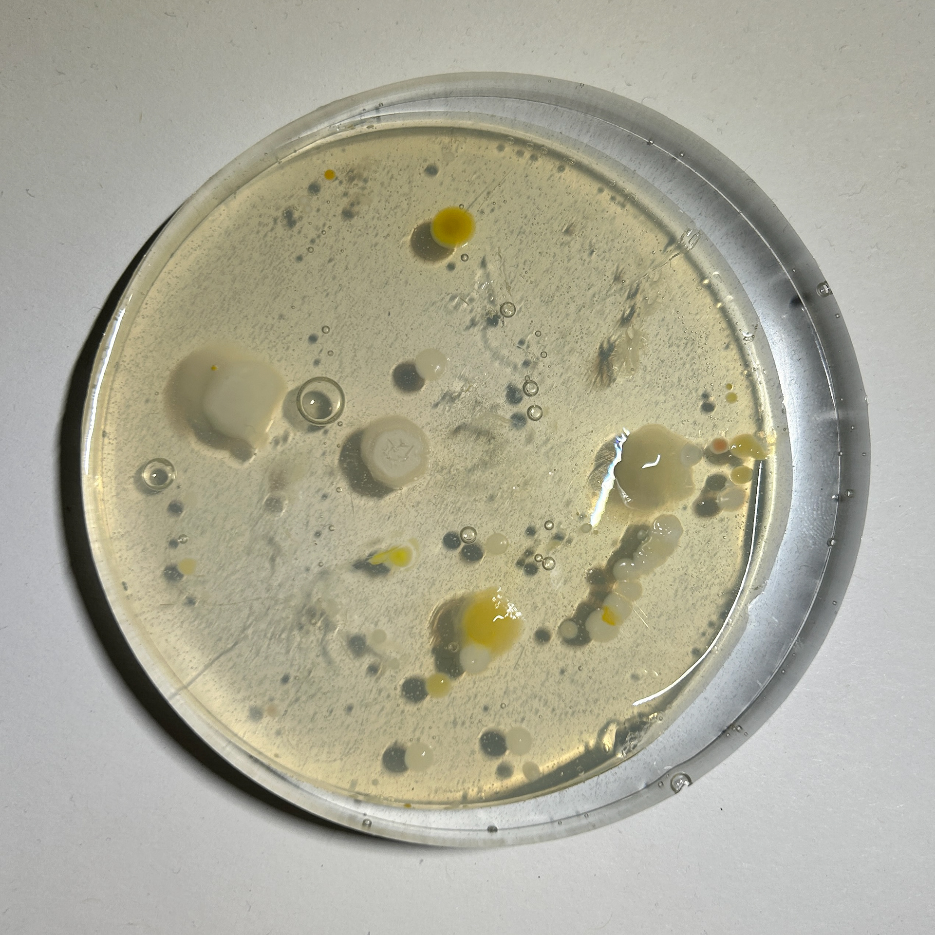
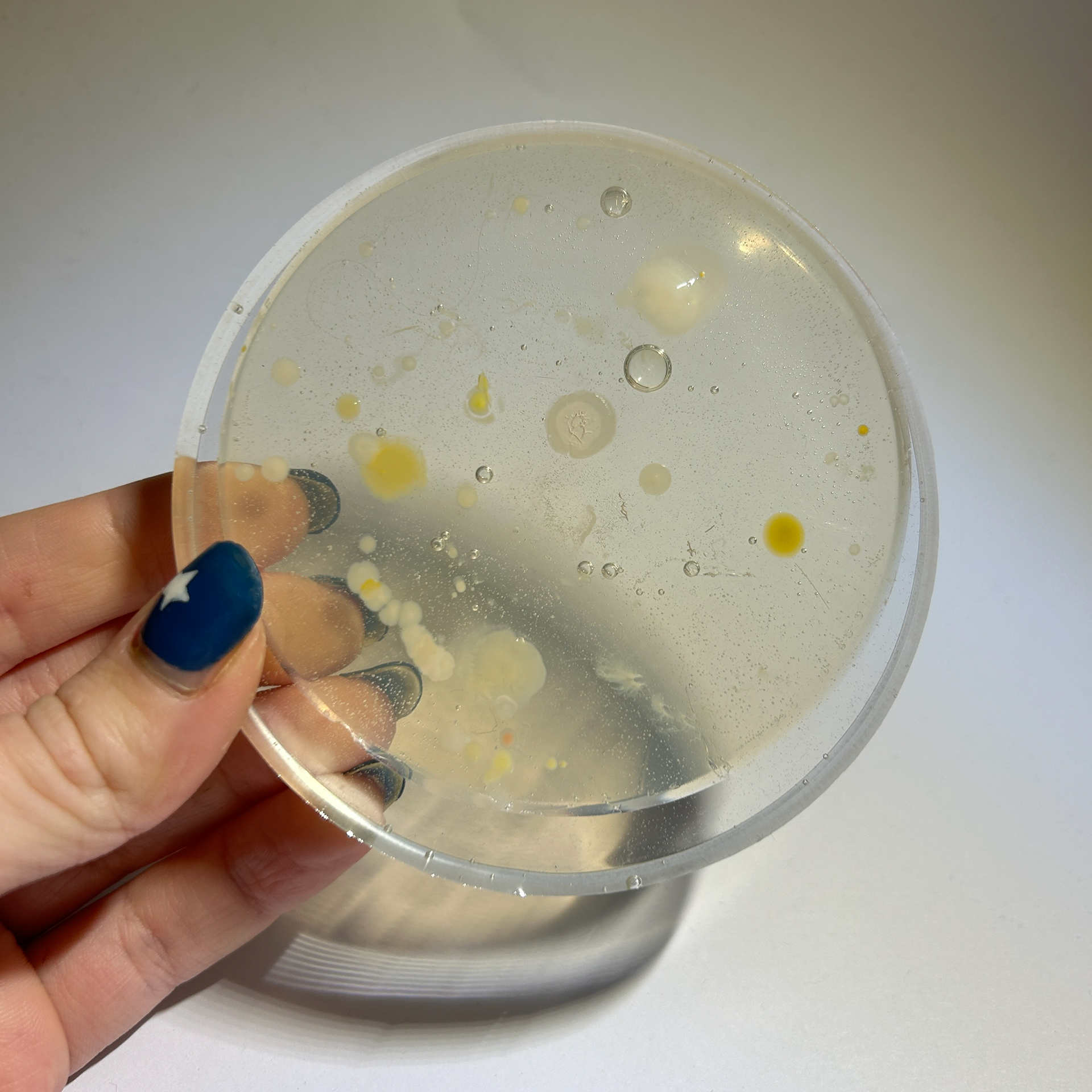
I thought about how to approach this and decided the best method would be to create a silicone mould. I would first cure a layer of resin, then add the agar containing the grown bacteria, and finally add another layer of resin on top.
To continue wit this idea, I needed to get inducted in silicone/rubber mould-making, as the silicone putty I had previously used was too small for this project.
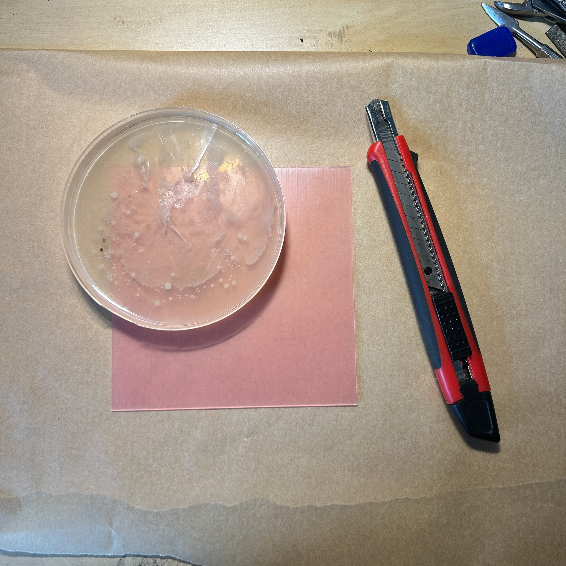
I had thought about what to use to make the negative space for the moulds and first thought about using laser-cut acrylic disks. This would allow me to have a couple of millimetres around the agar and therefore making sure I can thoroughly seal the bacteria. However, after speaking to Aiden in laser, he told me that the university laser cutters can only cut up to 6mm, as anything above this can cause the light to diffract and have a slight indent towards the bottom of the disc. He advised that I should use wood, however after speaking to Diane she told me that it would have to be sanded and oiled to get the flat surface that I wanted, which may cause a sheen to cover the resin / mould. After all of this information, I decided to first test my idea using a petri-dish and see if this would work. It would only give me about 1mm of space around the agar, however, I could trim the agar jelly with a knife if I had to, and use a laser-cut disc as a guide. There could be problems with this, as the disc may cause the cultures to be squished when I place the disc over the agar, however, this was a problem for later if it came to this.
Induction
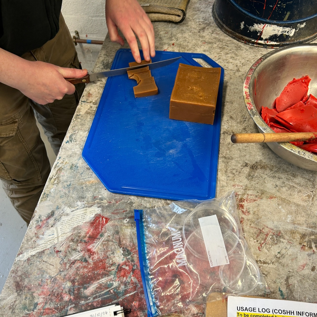
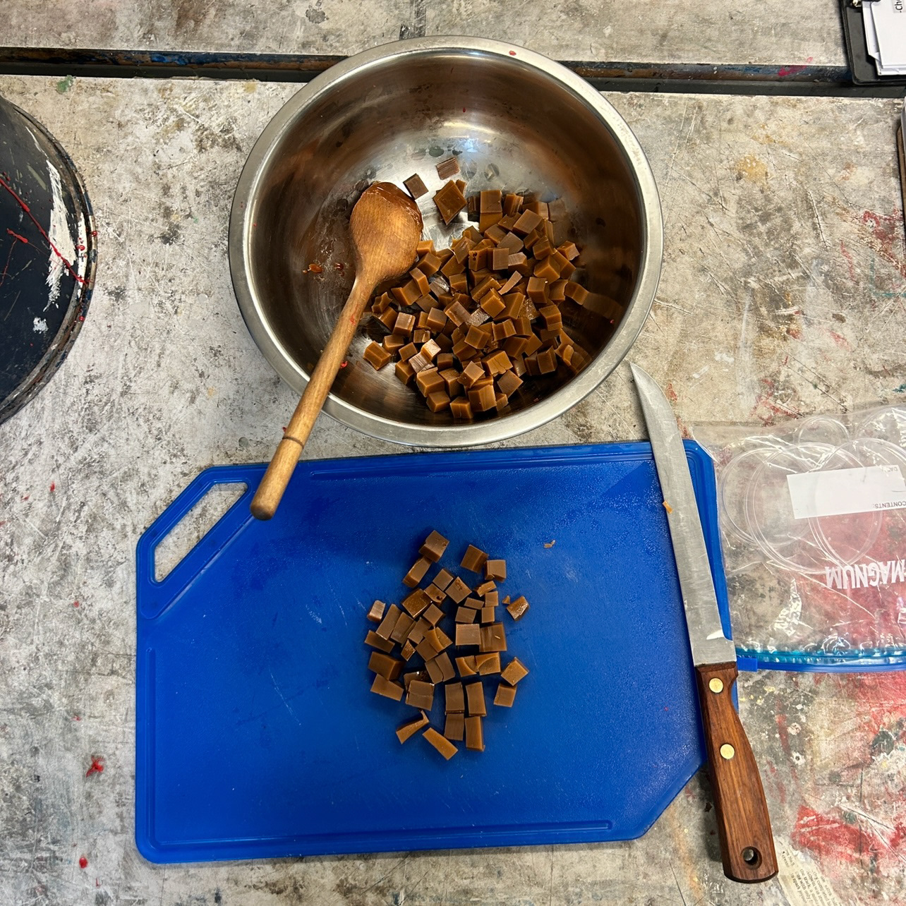
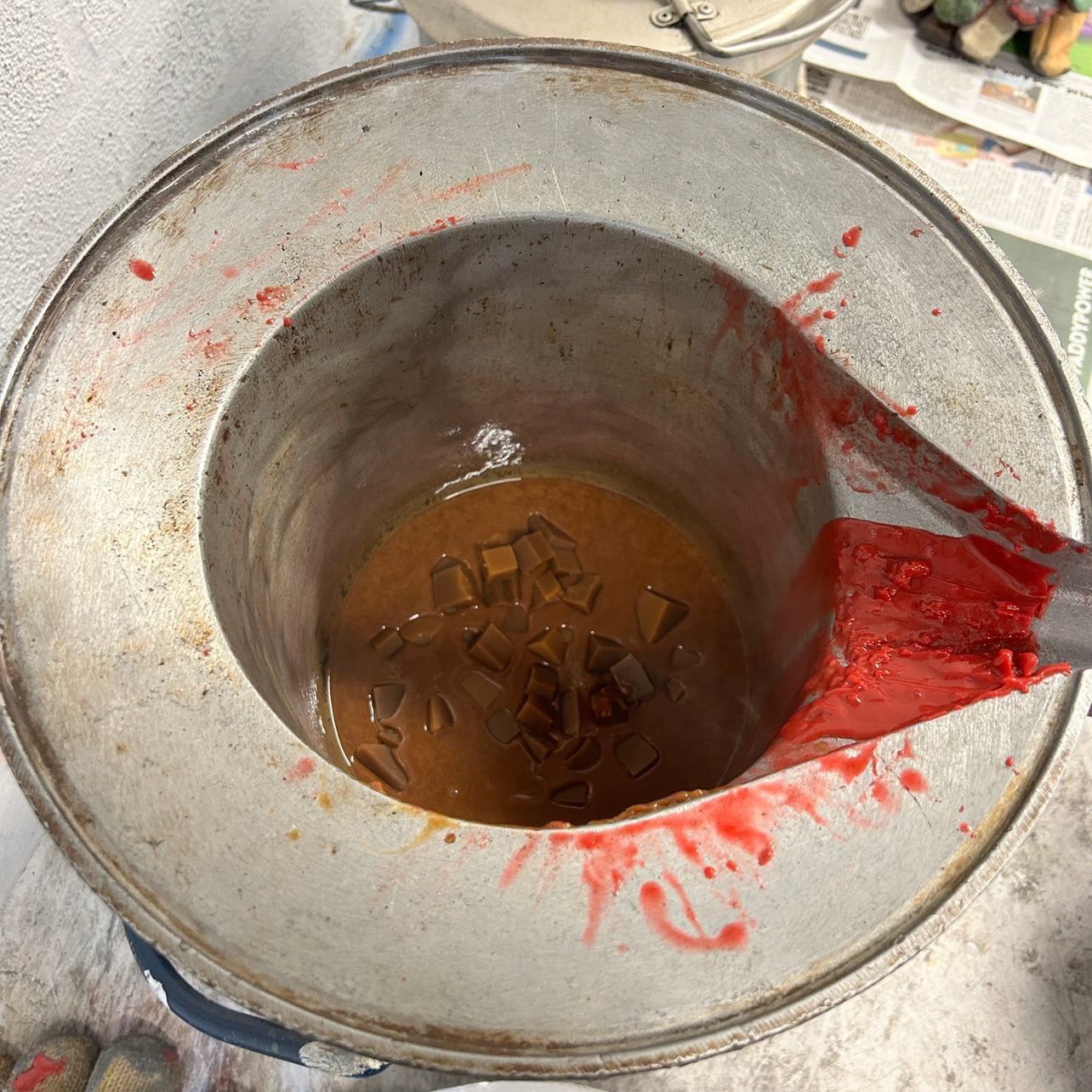
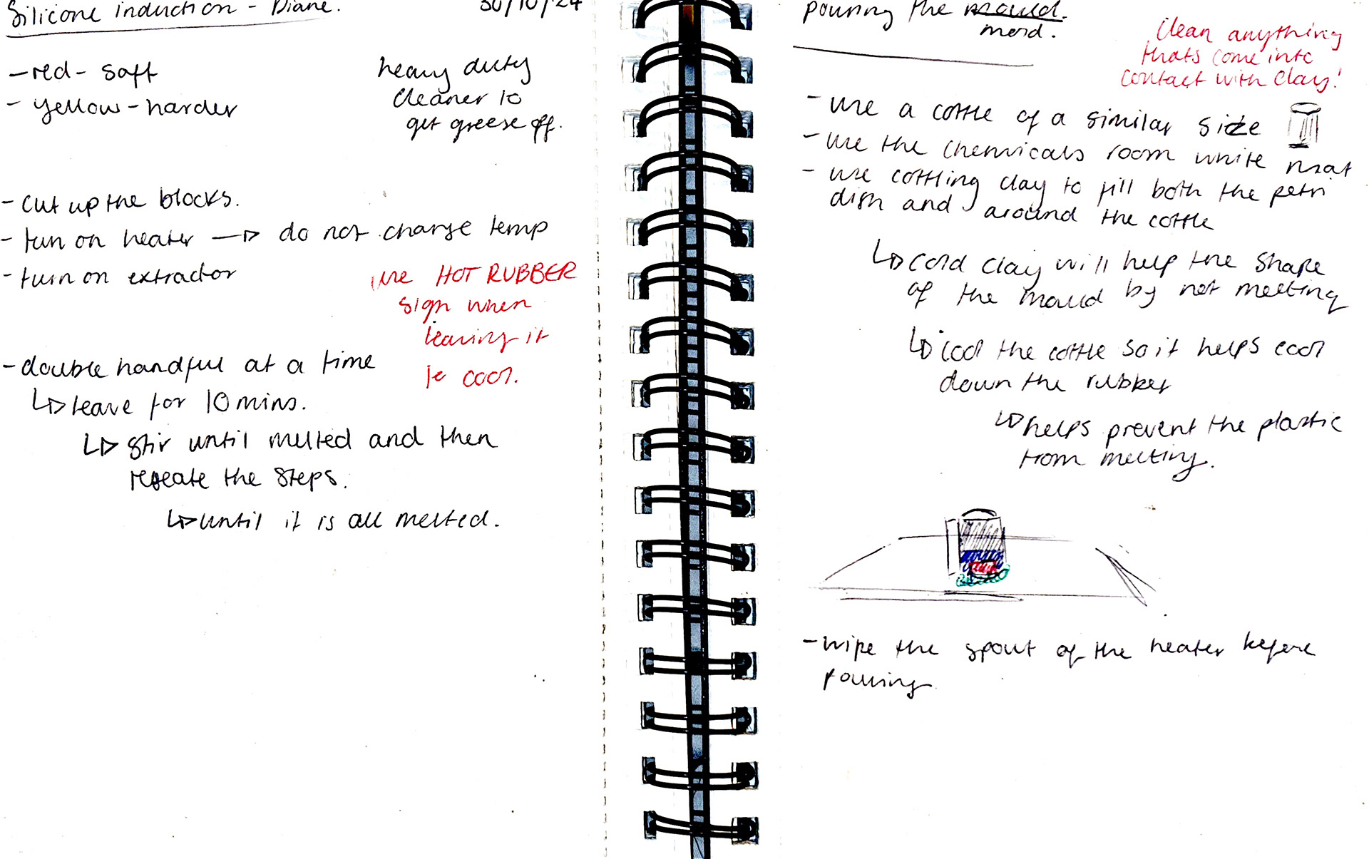
To start, I had to cut up the pieces of rubber to melt down, and then add to the heated crucible two handfuls at a time, waiting to add more when the previous handfuls are completely melted.
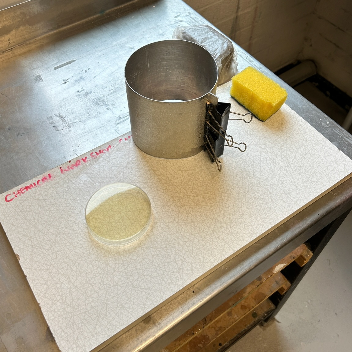
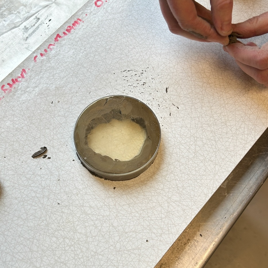
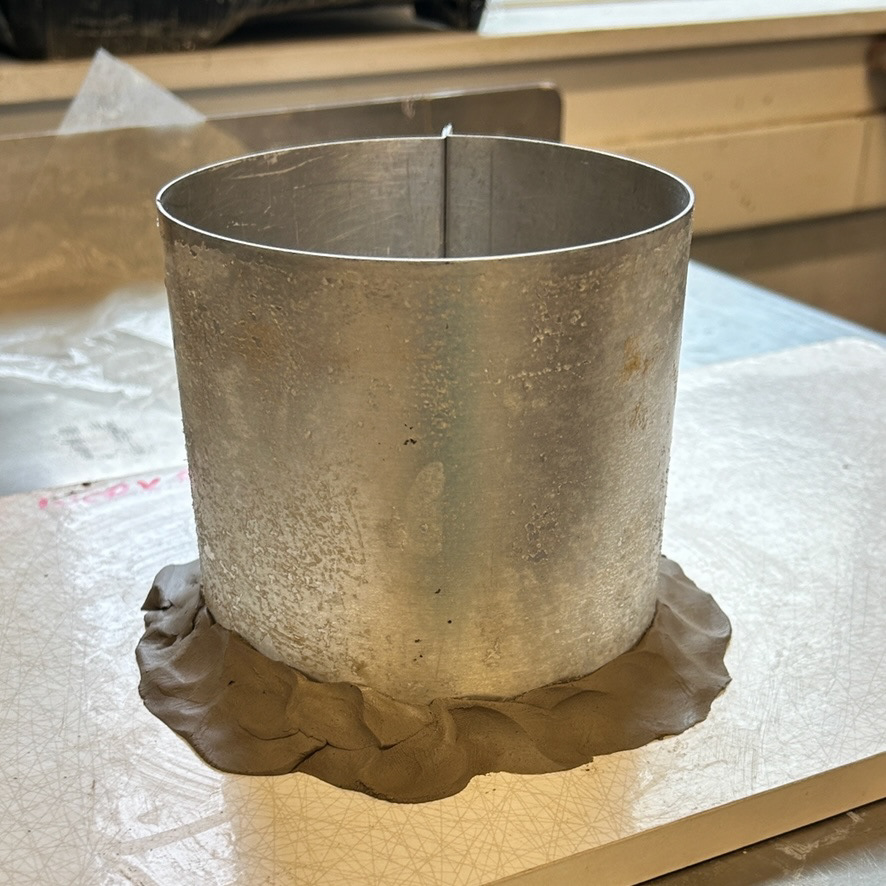
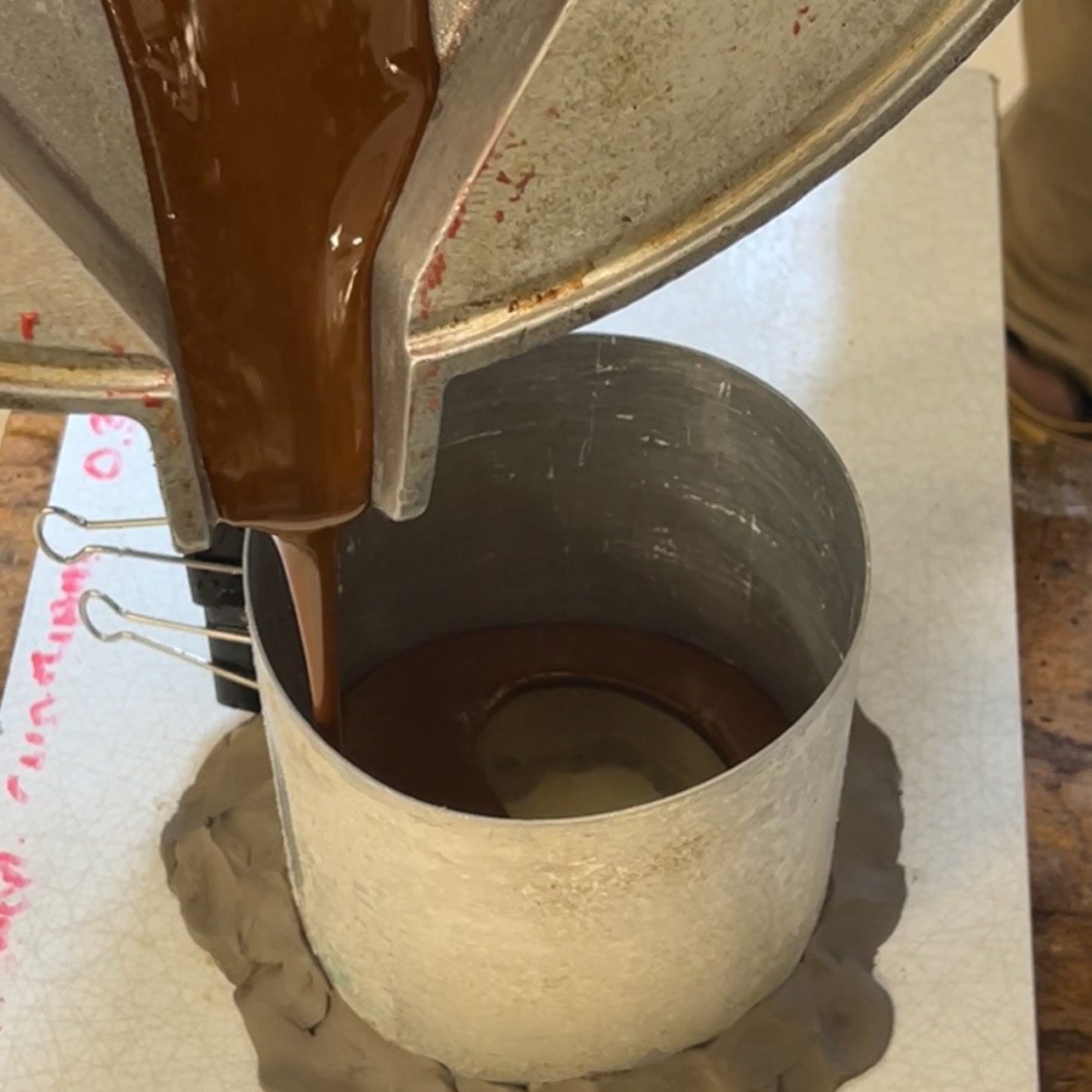
Before pouring the rubber over the petri dish, the dish had to be sealed to the board using cottleing clay to make sure it wouldn't move during the pour. This would also help keep the plastic cool and help reduce the risk of melting. The clay was then used to create a seal with the cottel before the rubber was poured over the dish. Before pouring, I let the hot rubber cool for at least 10 minutes, to help reduce the risk of melting the thin petri dish.
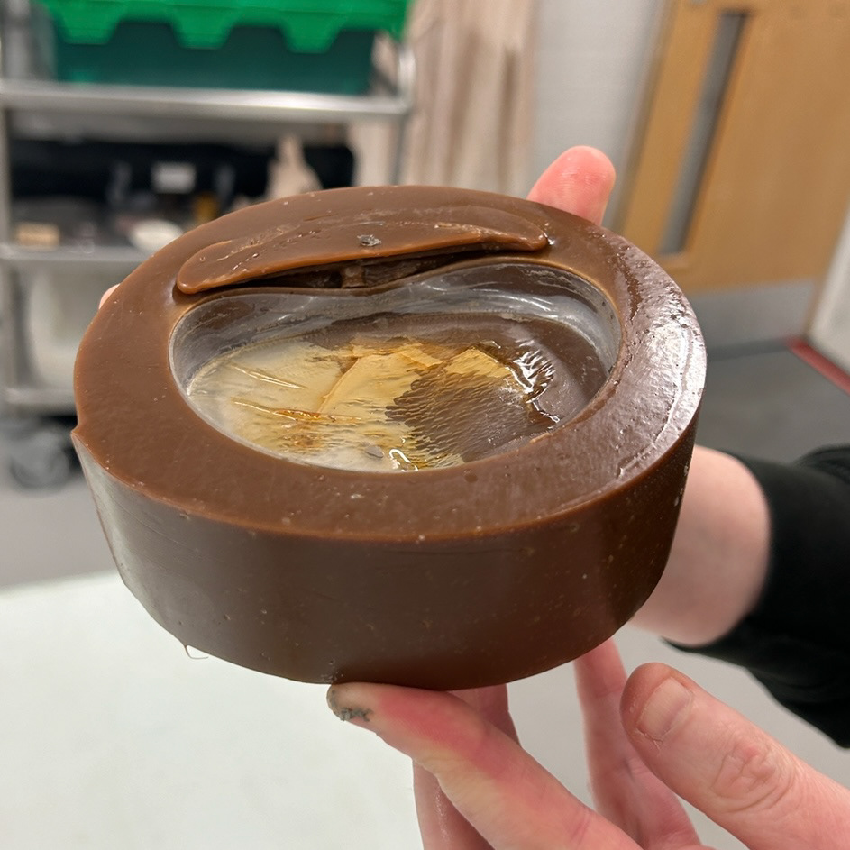
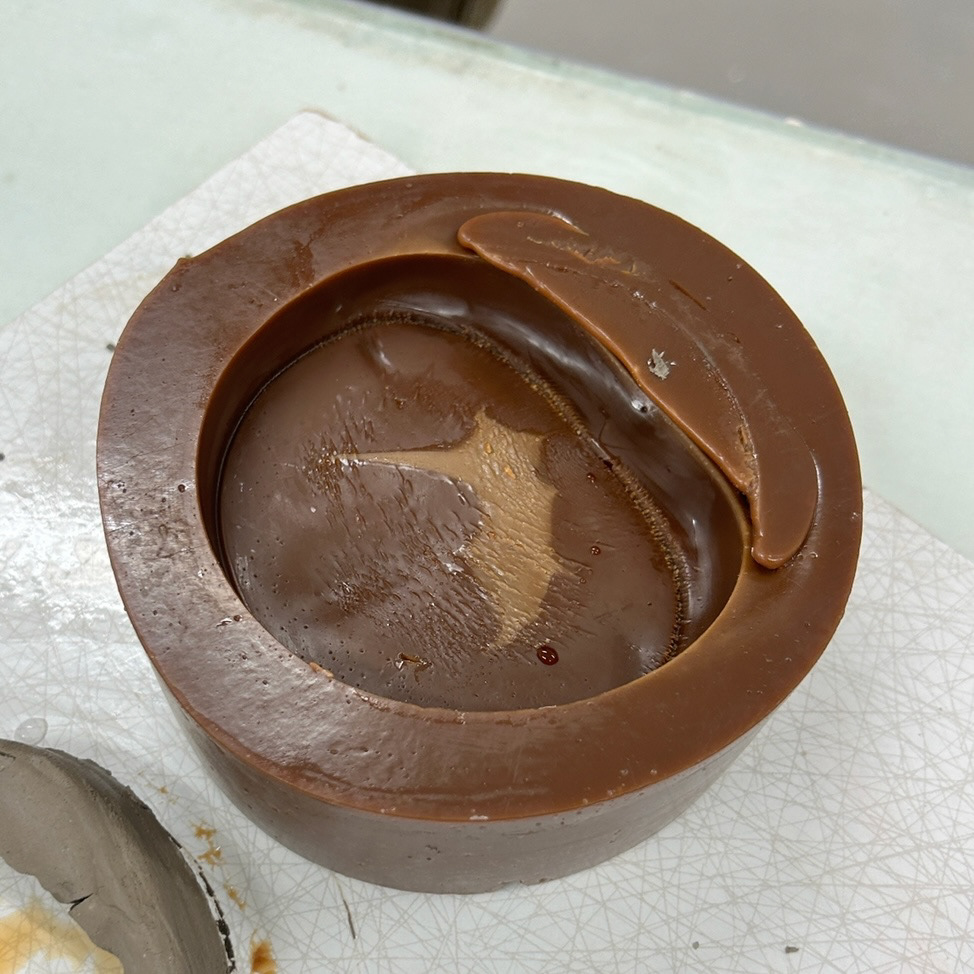
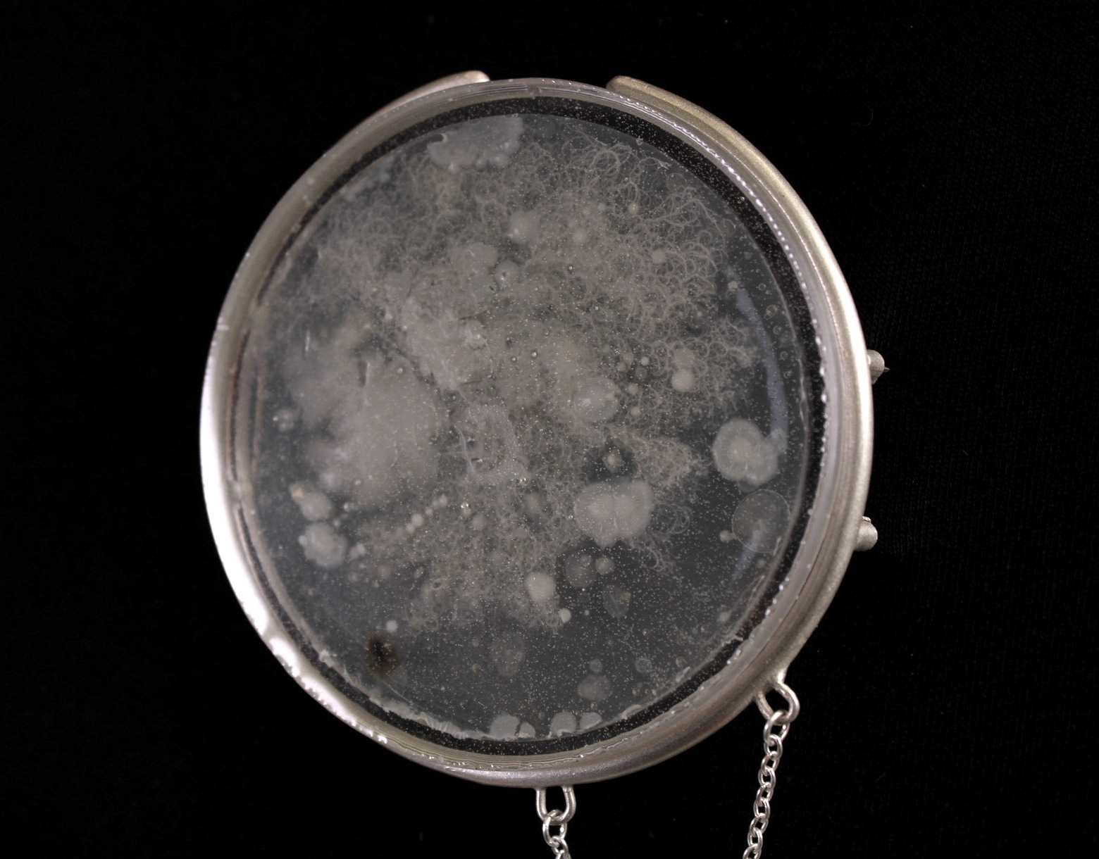
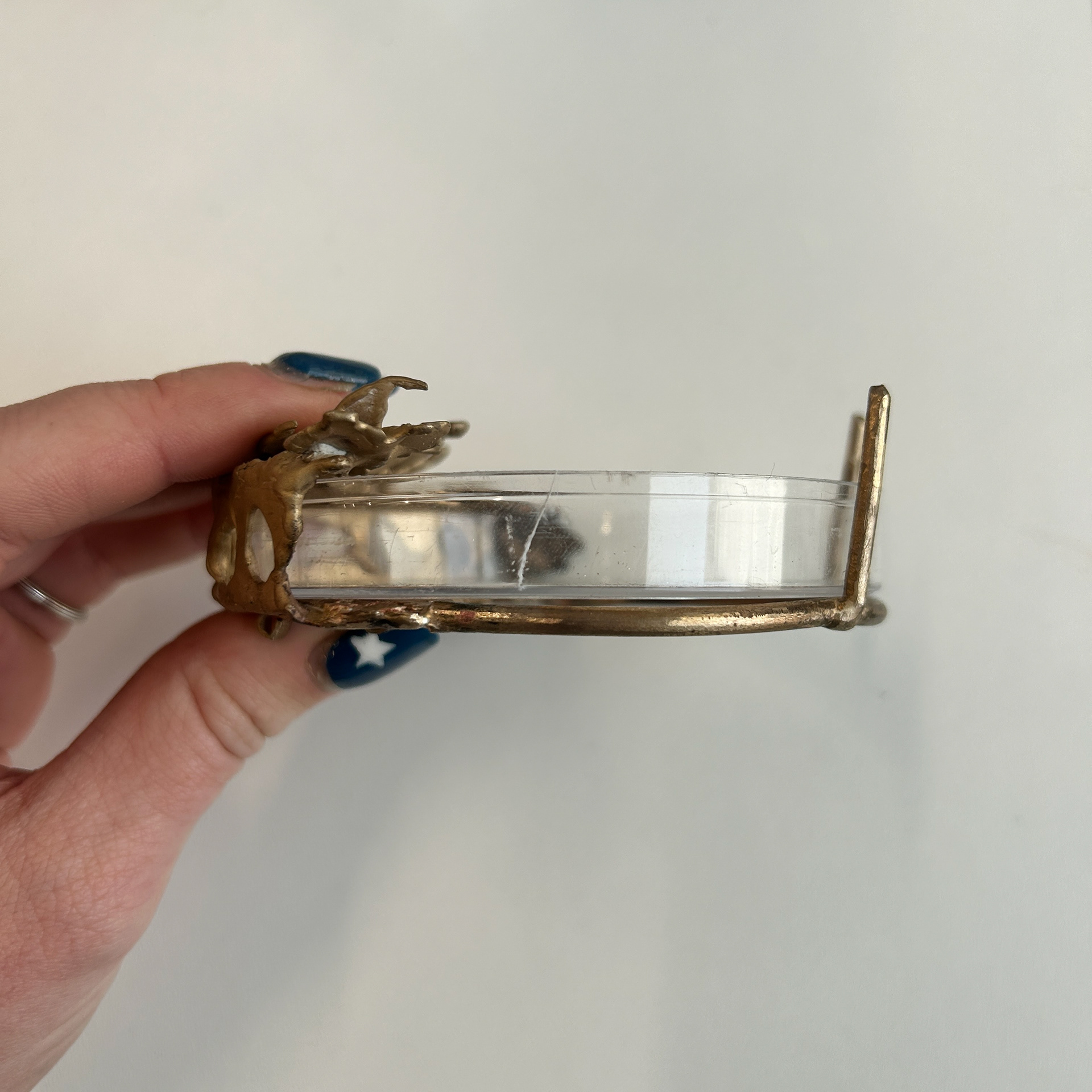
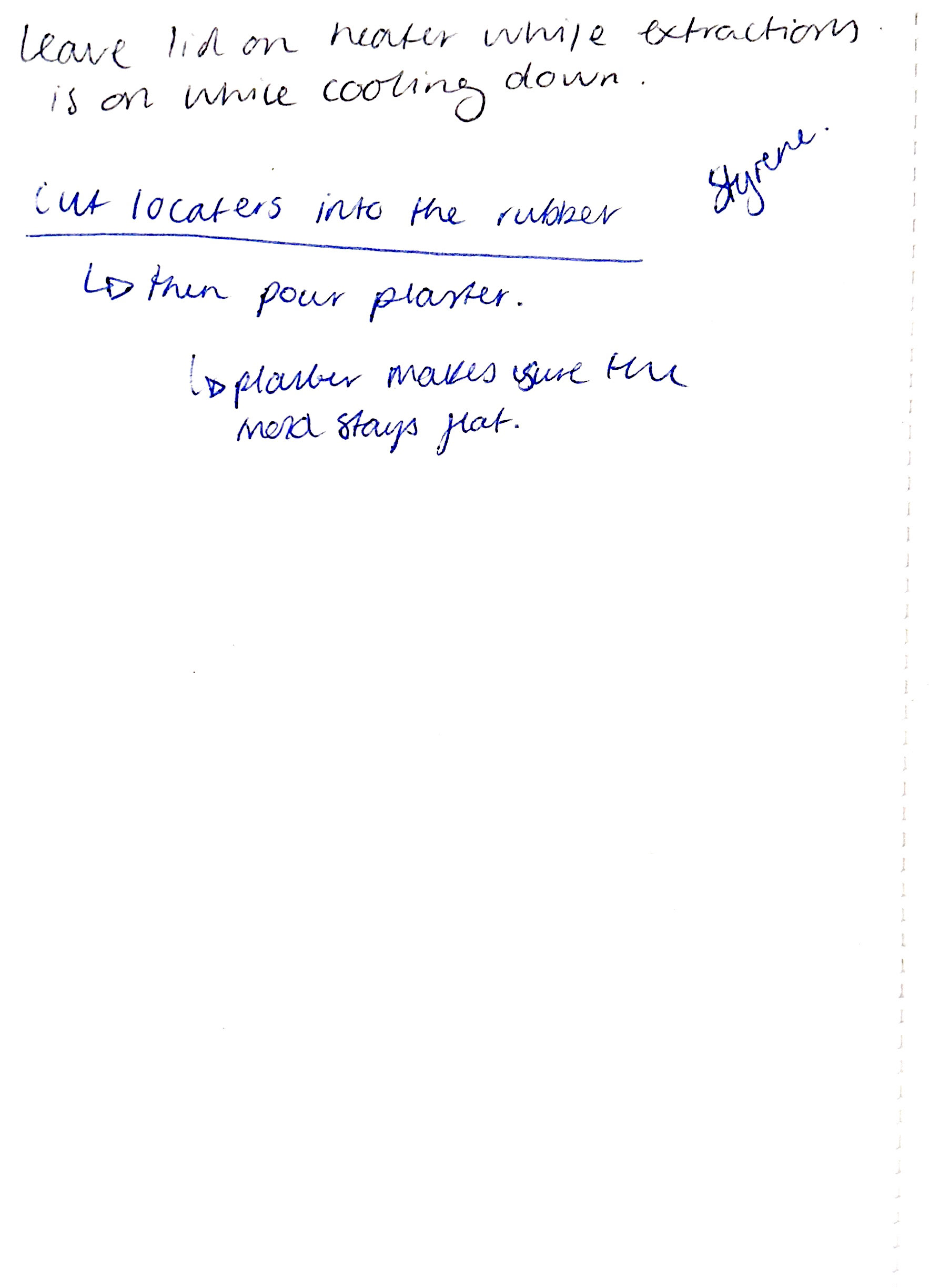
After leaving the mould to set over the weekend, I checked on the mould before pouring plaster on the back (to keep the back stable when turned upside down to use) and found that the dish had indeed melted. Diane explained that the space in the middle of the dish that we left without clay may have caused steam to build up and potentially escape, causing the weird bubbling.
To redo this idea, I have decided to look into redoing this method with solid laser-cut pieces that I will order from an external supplier so they can be thicker.
Testing a New Mechanism
8th November
After my tutorial with Mark, I went to test a new mechanism for securing the bacteria into the brooch. I decided to wax cast this as this would be the same technique that my final piece would be made from.
Wax Base
Full Circle

Full Circle
Semi Circle
Semi Circle
I began by creating the base of my design using the same process as my previous cast brooch. Next, I made tubing from scrap wax sheets, ensuring it was the right diameter to fit the bezel. I decided to make two variations to determine which would work best: one with a full tube attached to the back and another using a semi-circular tube that would lay flat against the back of the brooch.
Whole tubing
Semi-circle tubing
Next, I tested the fit of different tubing styles and added a small wax dot to secure the wire mechanism in place, as shown on my 'Unit X - Research and Development' page. While attaching the mechanisms, I had to carefully consider the angle, especially since the brass wire has a rounded profile. A simple 90° angle wouldn’t work on a curved piece, so I aligned the mechanisms to match the natural curvature of the wire for a better fit.
Casting
14th November
After casting the brooch, I realised that the mechanism was far too bulky, and the addition of small tubing to hold the wire looked unrefined and unfinished. Around this time, I had just received feedback during a group crit, which led to changes in the brooch design. Given this new direction, I decided not to continue experimenting with the current setting.
Agar Resin Samples
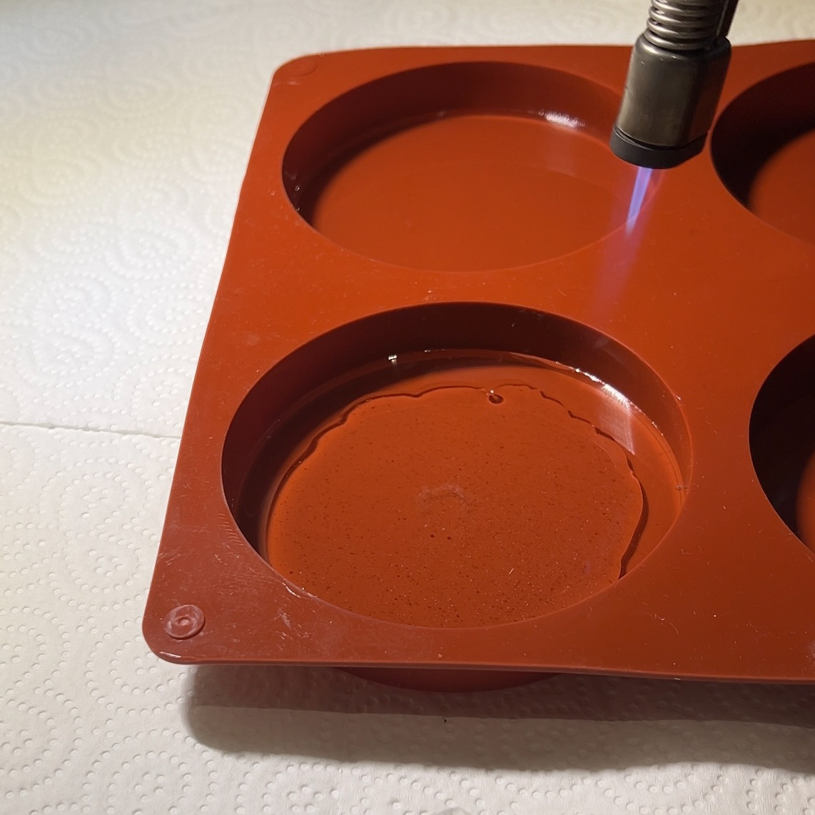
While I waited to perfect my 3D prints to make custom silicone moulds, I tested my idea using a silicone baking dish and epoxy resin. This also meant that I could see if I needed to make any adjustments to my CAD designs.
Jewellery Bacteria Samples
Silver Bangle
Silver and Black Onyx Cufflinks
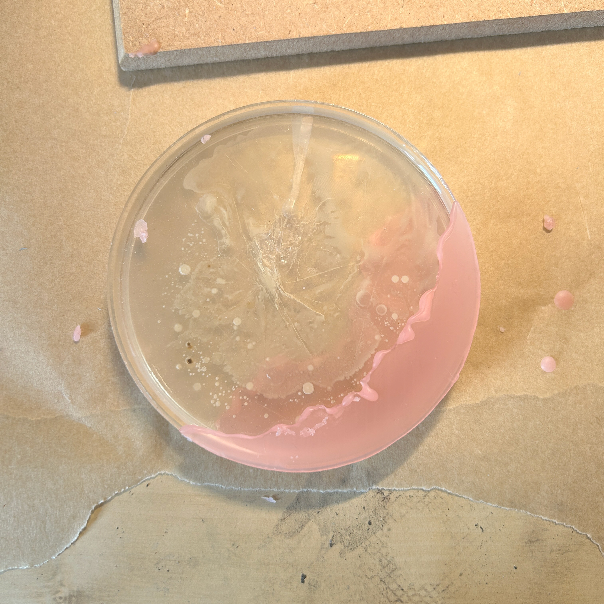
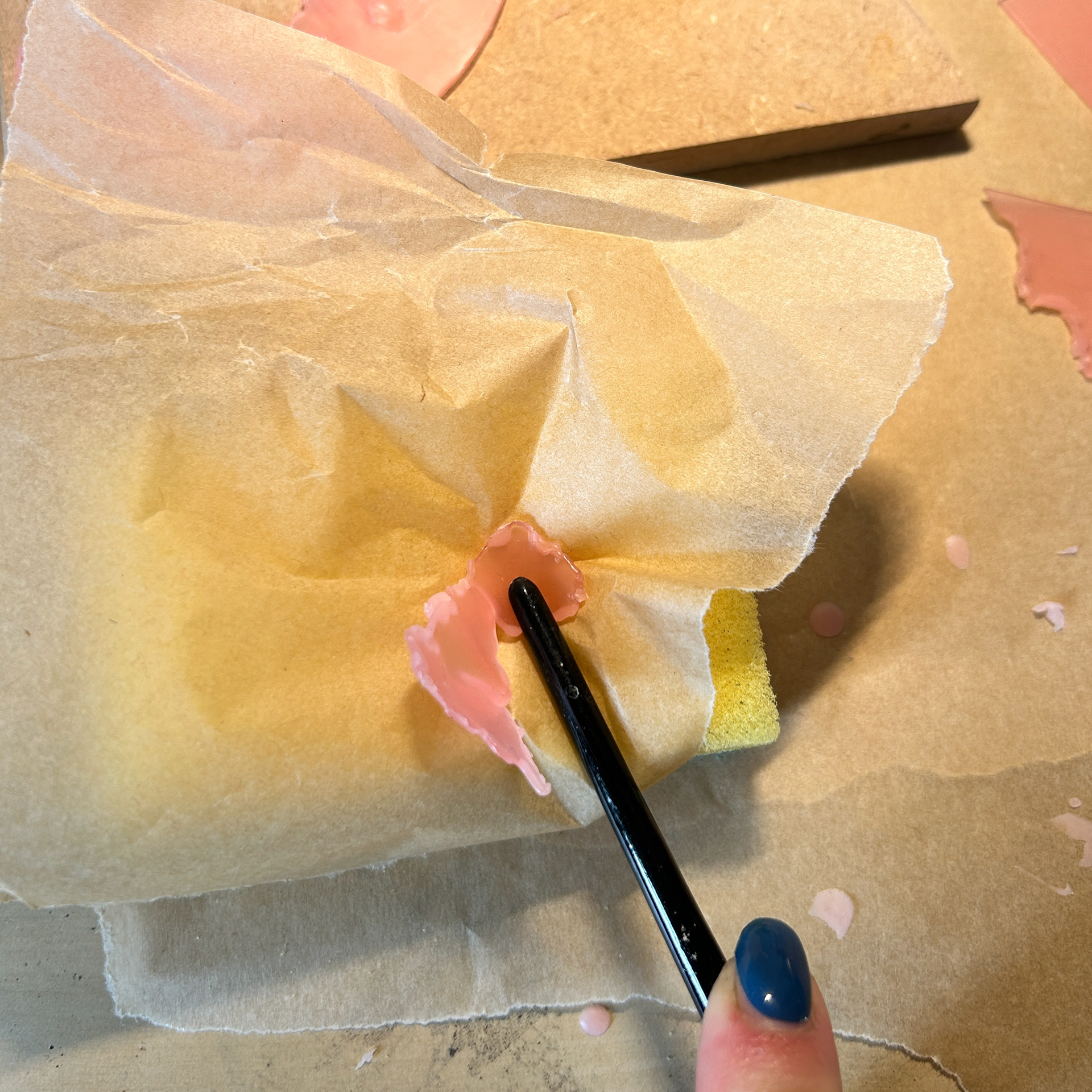
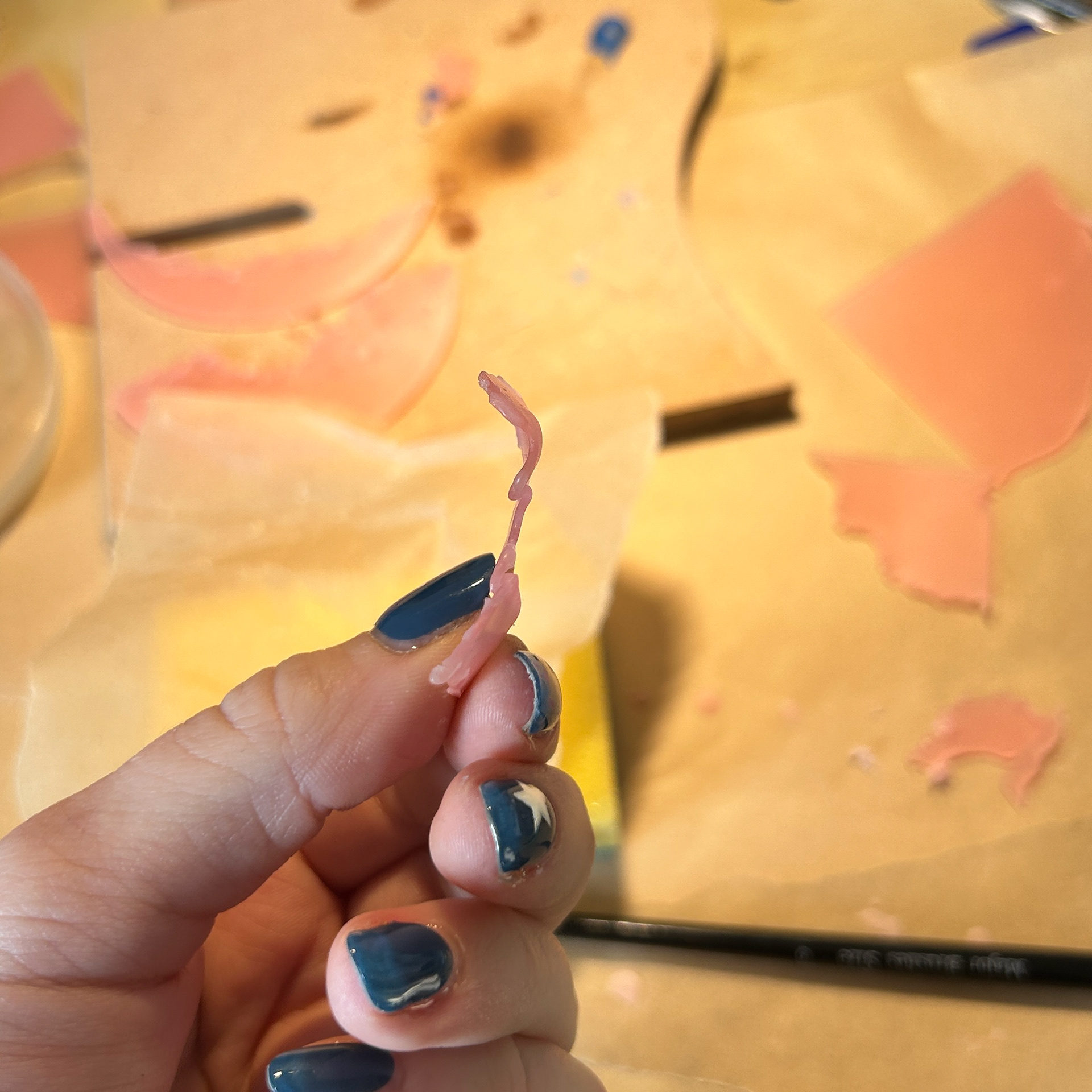
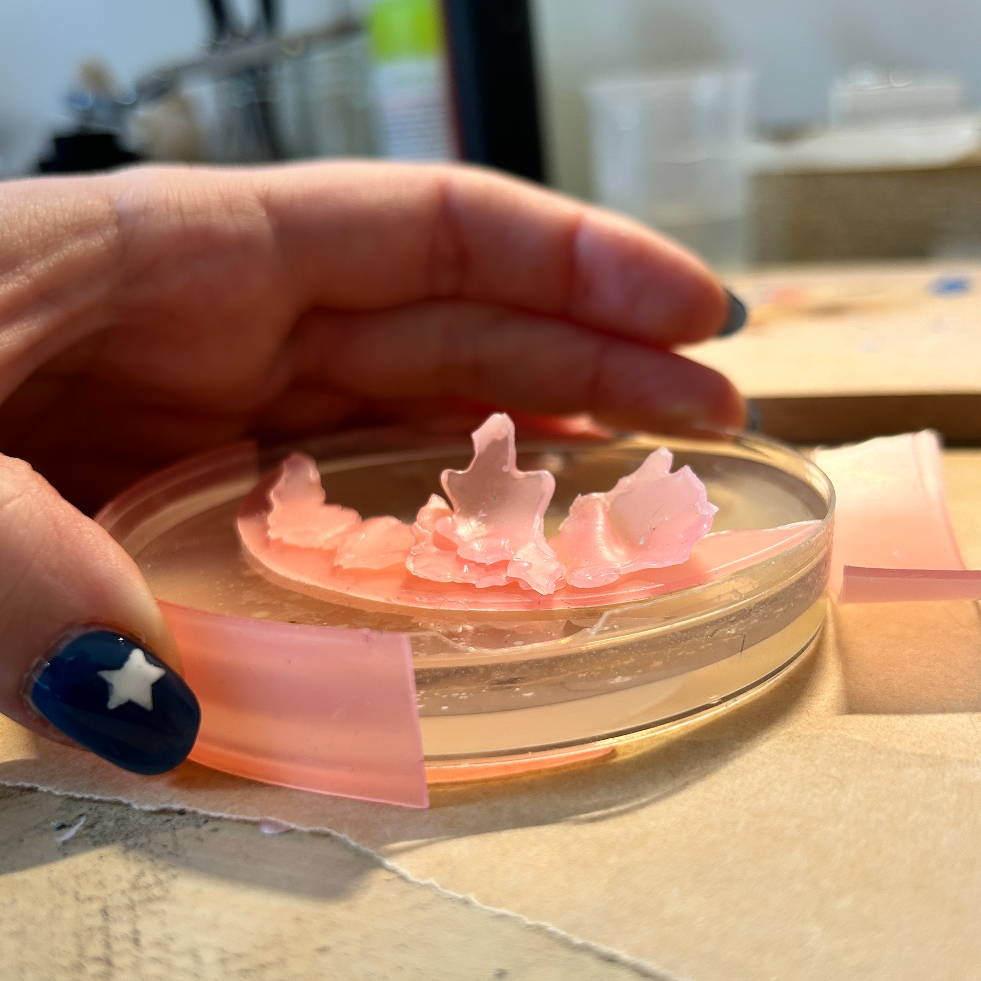
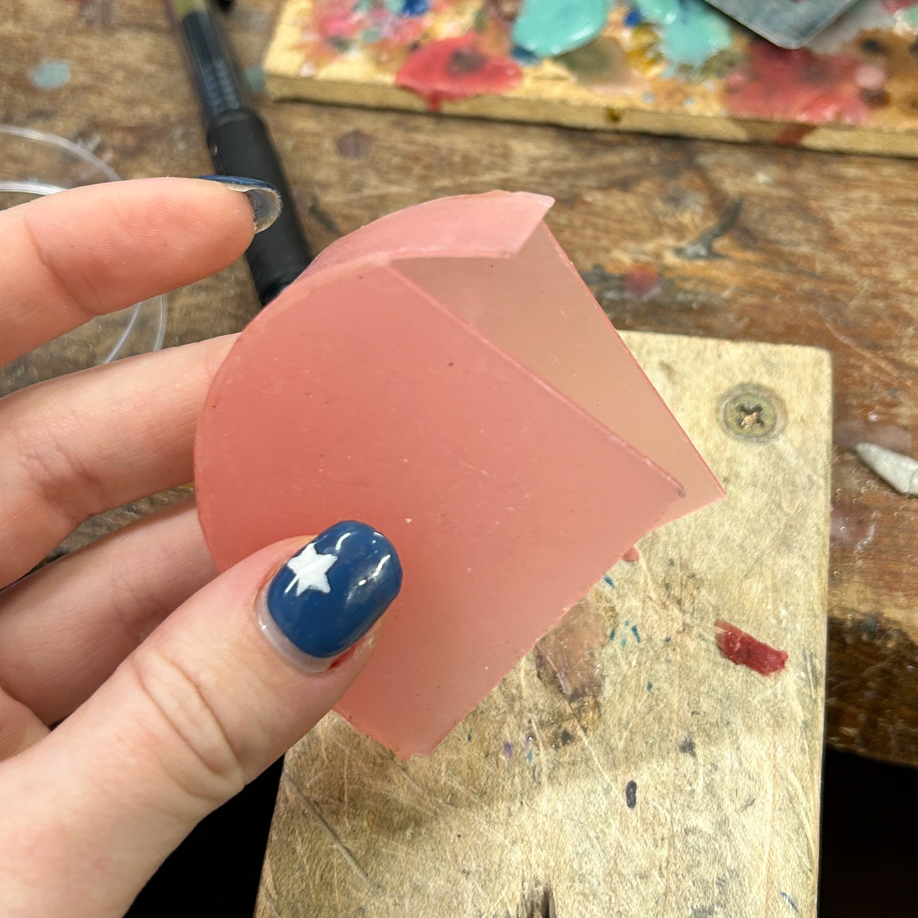
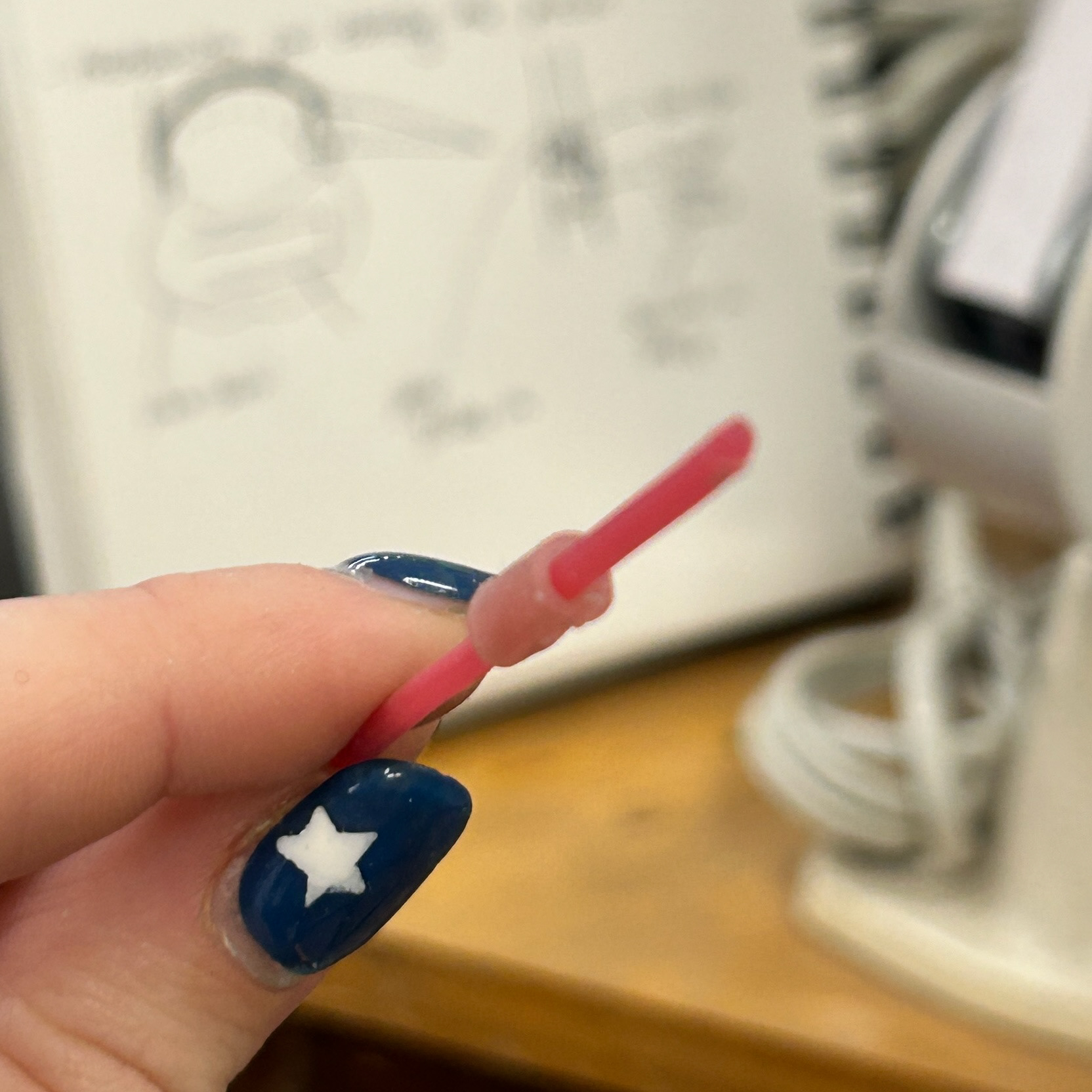
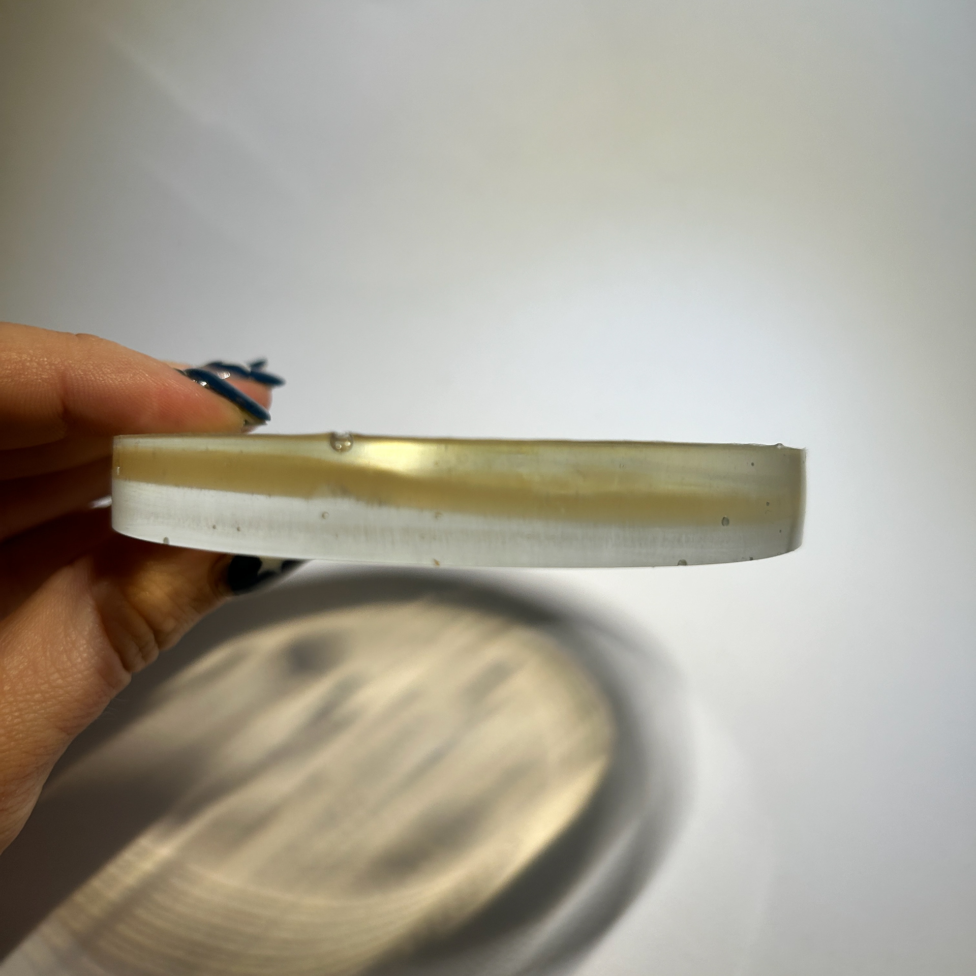
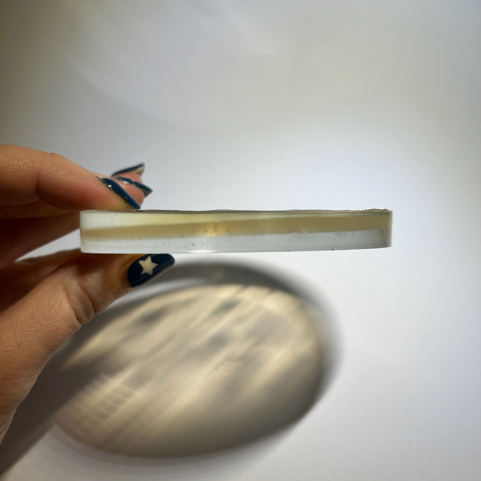
Here I show the process of how I got the agar out of the dish.
I used a tool that I have previously used for enamelling and wax casting, however, the small spatula shape meant that I could get underneath the agar with minimal damage.
I first started by breaking the seal from around the dish, and then later (not recorded) I began to lift the whole agar circle out.
This meant that I could then easily lift the agar out of the dish when it was ready to be used.
To make my samples, I started by curing a thin layer of resin at the bottom of the silicone dish to create a stable base. Next, I poured a light top layer, acting as a glue to hold the agar in place and prevent it from shifting when adding the final epoxy layer. Using a blowtorch on low heat, I carefully removed any air bubbles.
Afterwards, I gently peeled the agar from the petri dish and placed it in the centre of the resin circle, pressing it down very gently to remove as many air bubbles as possible.
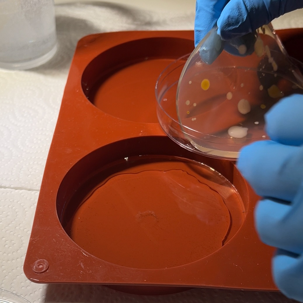
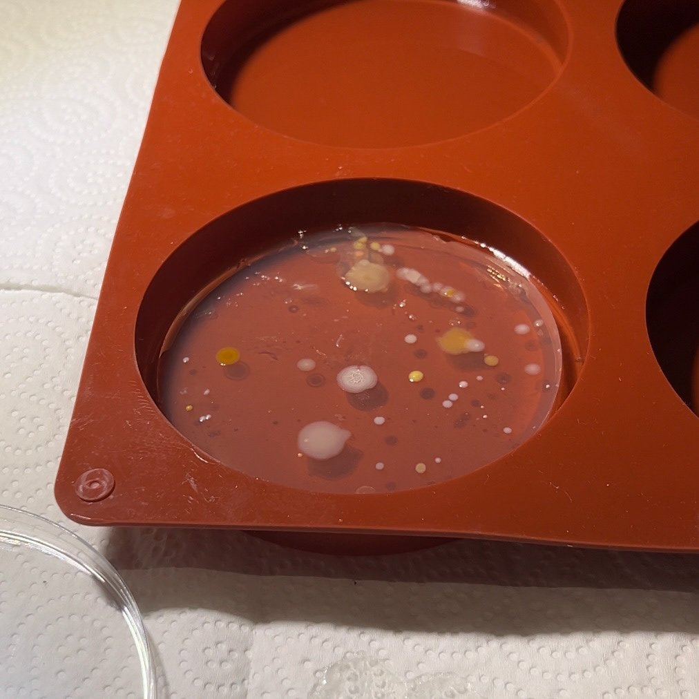
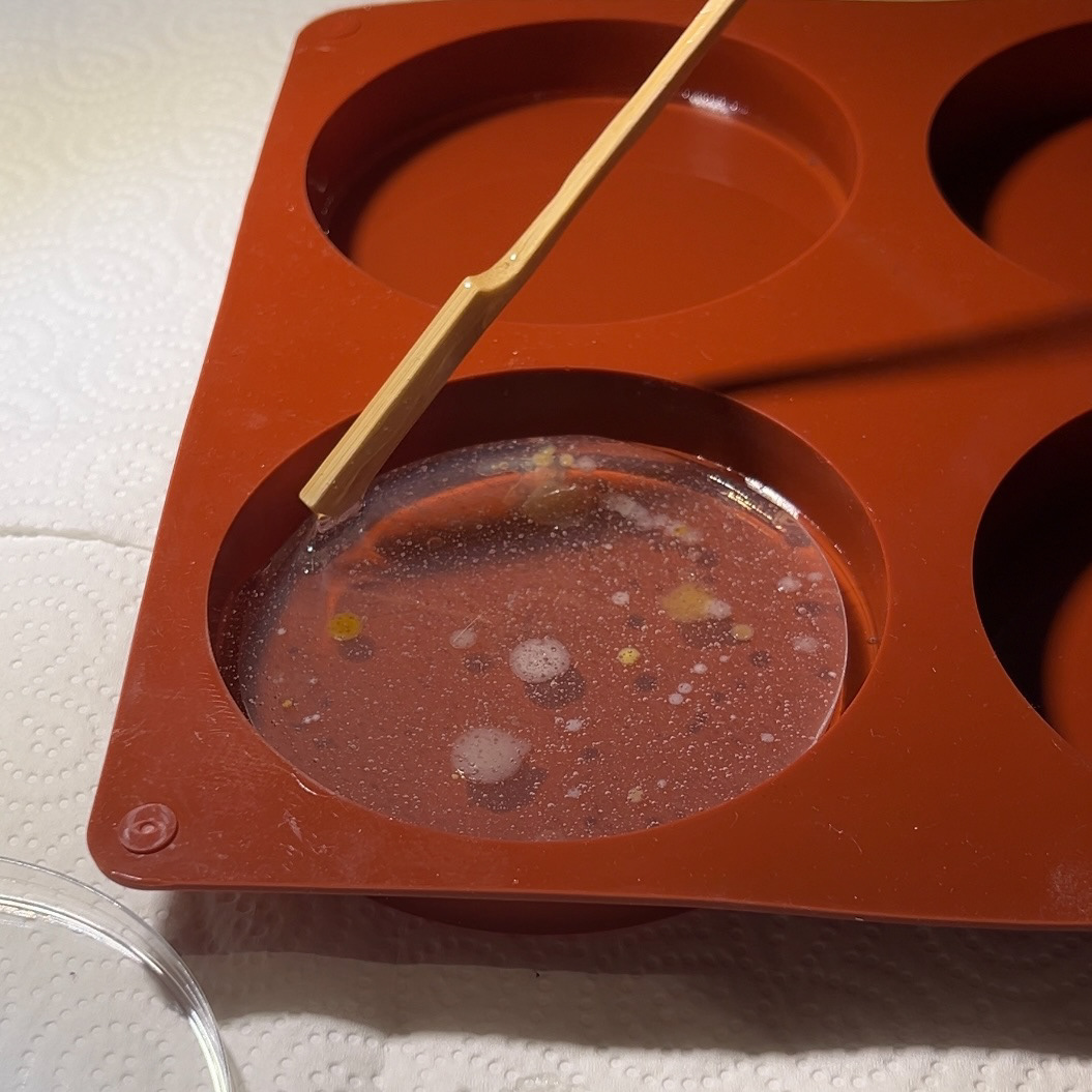
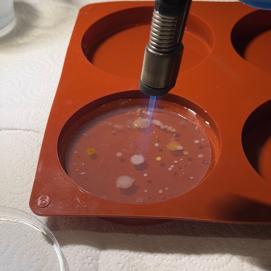
When I was satisfied with the position of the agar, I poured over the rest of the resin, making sure all of the gaps around the sample were filled. I then used my blowtorch to remove the air bubbles and repeated these steps with my other sample.
Results
Silver Bangle
Silver and Black Onyx Cufflinks
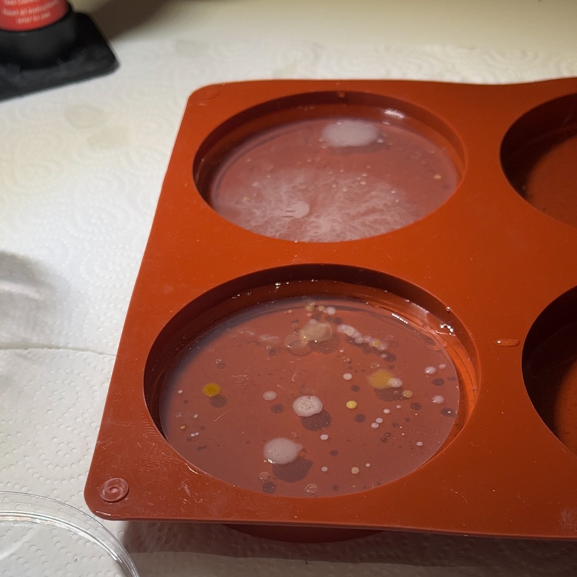
Although the concept worked in principle, the execution did not meet my standards. Pouring a layer of resin before adding the agar turned out to be a mistake, as it resulted in air bubbles and inconsistencies in the height of the agar. In the future, I think brushing on a very thin layer of resin would be a better approach. Additionally, there was a noticeable tilt in both samples, most likely due to the uneven surface where they were left to cure. Next time, I will ensure the surface is perfectly level, maybe my using a piece of greyboard.
The moulds I used were quite thin, which made surface inconsistencies even more apparent. When creating my own moulds, I plan to make the base thicker, as this should help compensate for minor surface unevenness.
Lastly, I noticed some silicone stuck to the resin. I suspect this was caused by excessive heat from the blow torch, and possibly overheating the sides of the silicone. In my next tests, I will be more cautious when using heat to remove air bubbles.
My next approach will be using the custom silicone mould made using 3D printing. I will also experiment with UV resin as this can cure within a matter of minutes, reducing the risk of any movement during the curing process.
3D Printing
12th November
Version 1
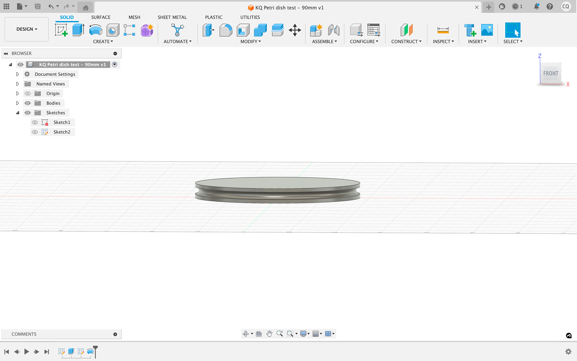
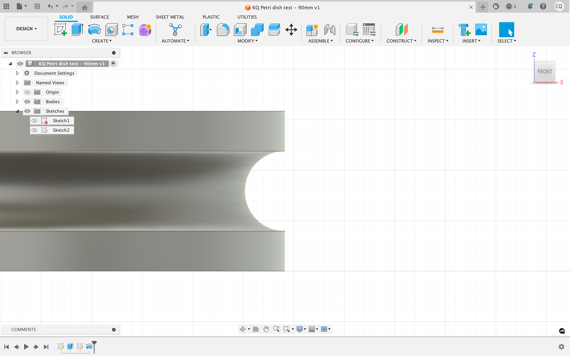
Following the group crit with Geoff, I took his advice and started working on the new setting idea using Fusion 360. I chose Fusion because I find its tools and interface more user-friendly, though I’m aware that I need to become proficient in Rhino as well, given its specialised jewellery design plug-ins that will prepare me for life post-graduation.
I created an initial CAD sample in Fusion, starting with a rough concept. The idea was that this would be used to create a custom (cold curing) silicone mould for my bacteria/resin, and silver wire would wrap around the bezel to hold the piece in place.
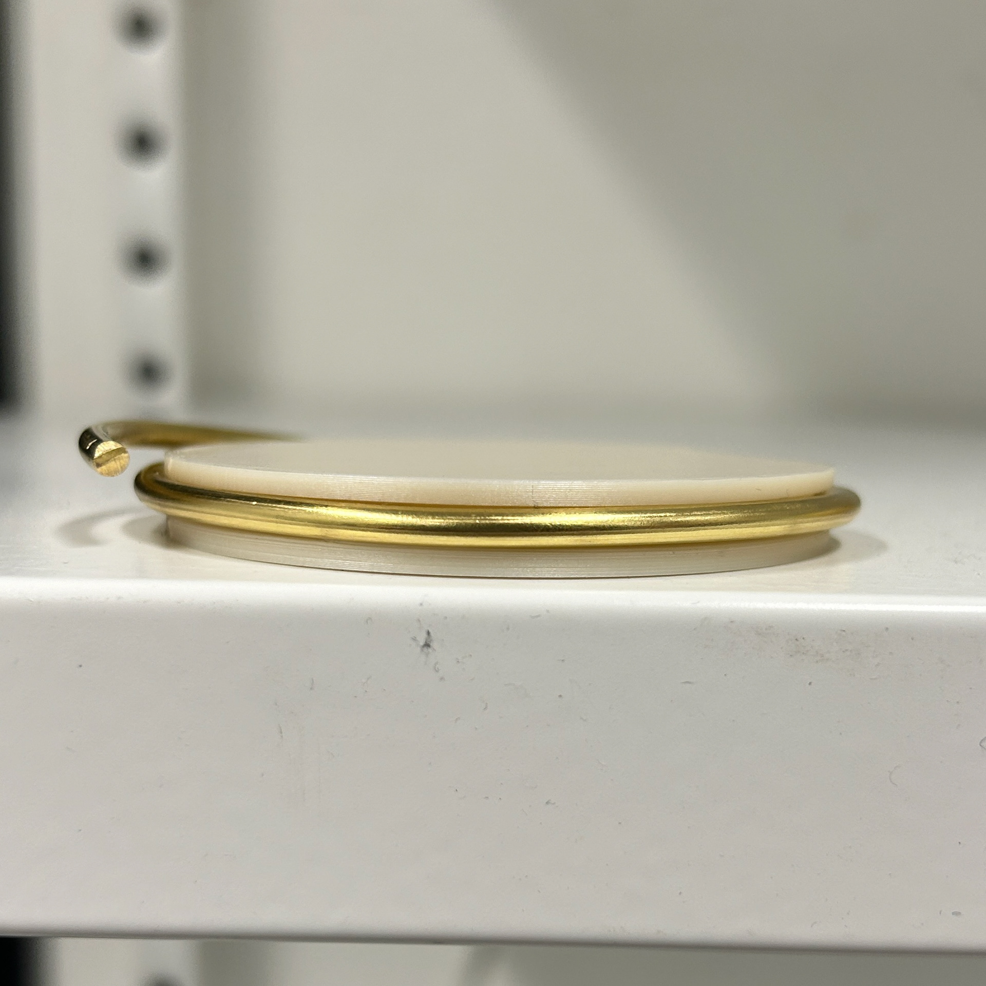
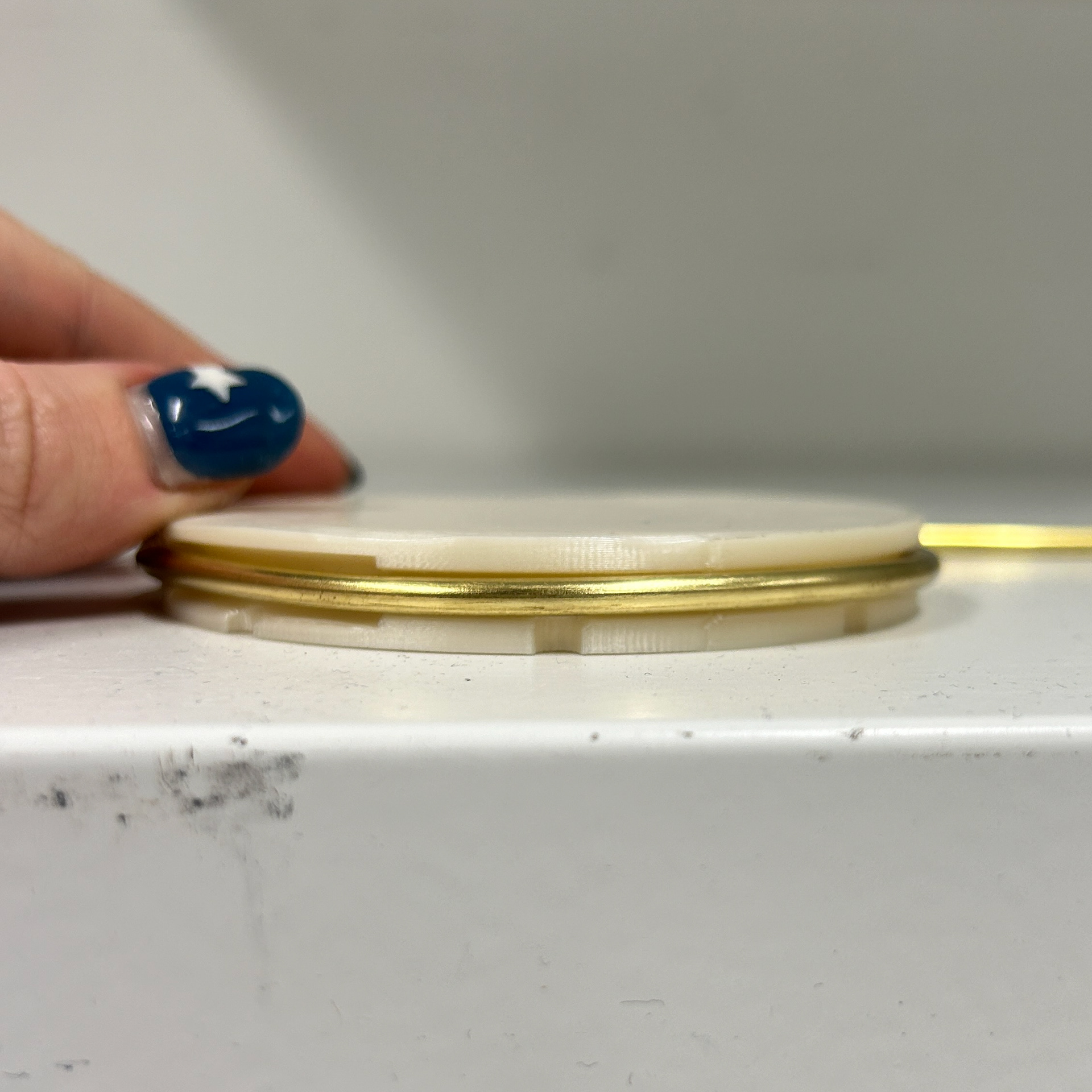
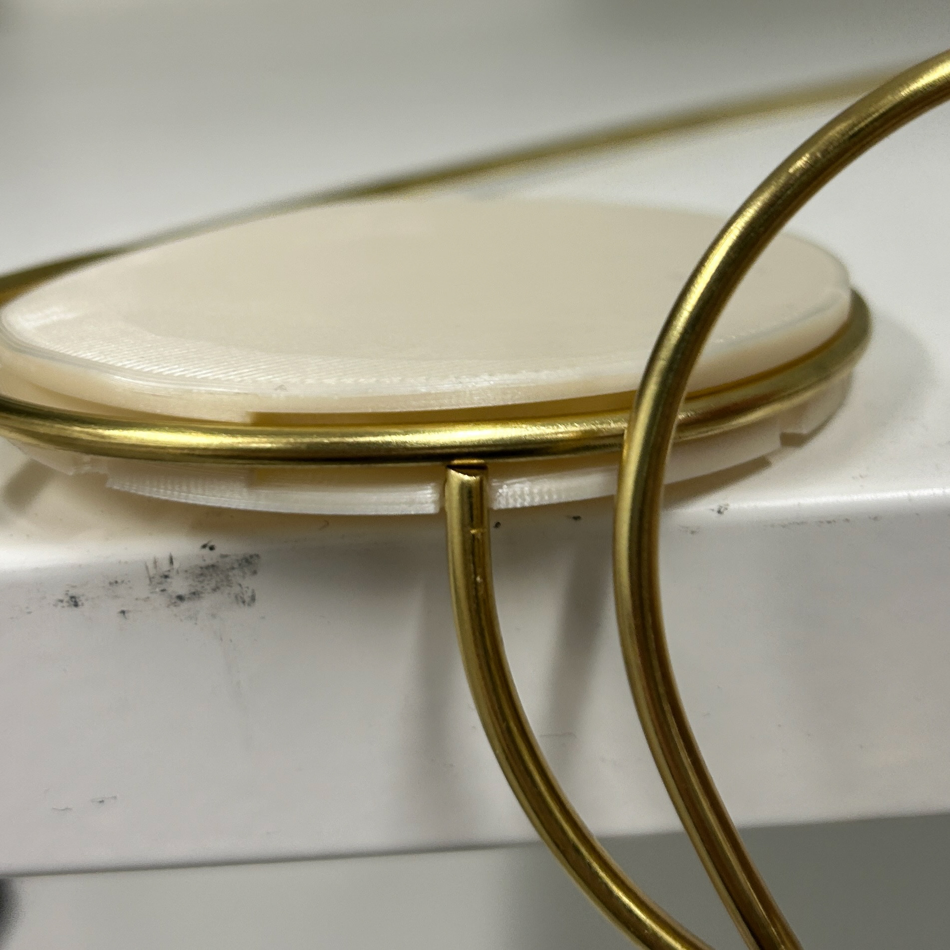
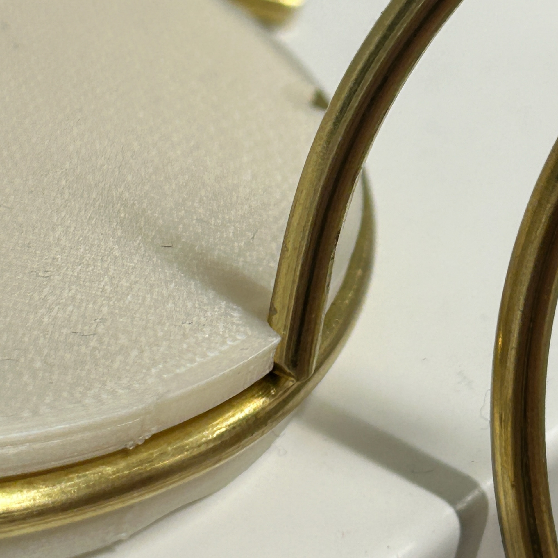
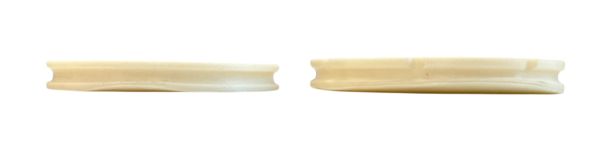
Here are the results of my first test:
Dimensions: 69mm x 8mm PLA print using 3.25mm brass wire.
While I used brass for this test, as mentioned previously, the final piece will be made from silver.
I’m pleased with how clean and seamless the setting appears. However, I now need to consider a mechanism for securing the dish, especially since soldering isn’t an option due to the resin that will be secured within the setting. As well as that, the dish had a slight lift at the bottom of the sample where it was next to the printing bed. However, this was fixed in later samples by moving the position of the print to one of the corners of the printing bed in Cura.
Version 2
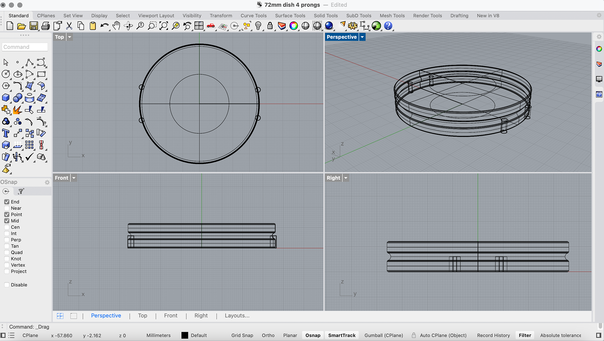
For another test, Geoff showed me how to incorporate space for prongs and a larger indent for a mechanism using Rhino 3D.
I liked this approach even more, as it allows the piece to be highly customised and tailored to the specific needs of my design. I enjoy crafting each element myself rather than relying on ready-made components, and by 3D printing these parts, I’m establishing a workflow that can be applied to future projects as well. This process is transforming the petri dish from a simple sample display into an integral component of my design.
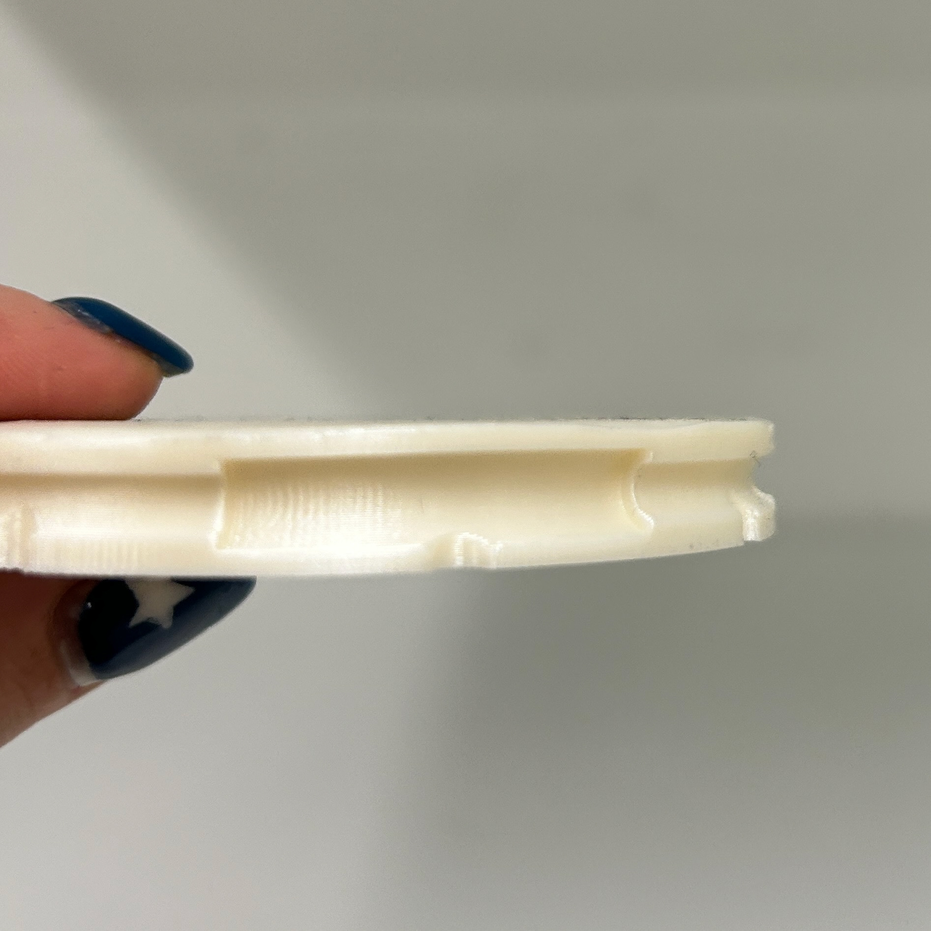
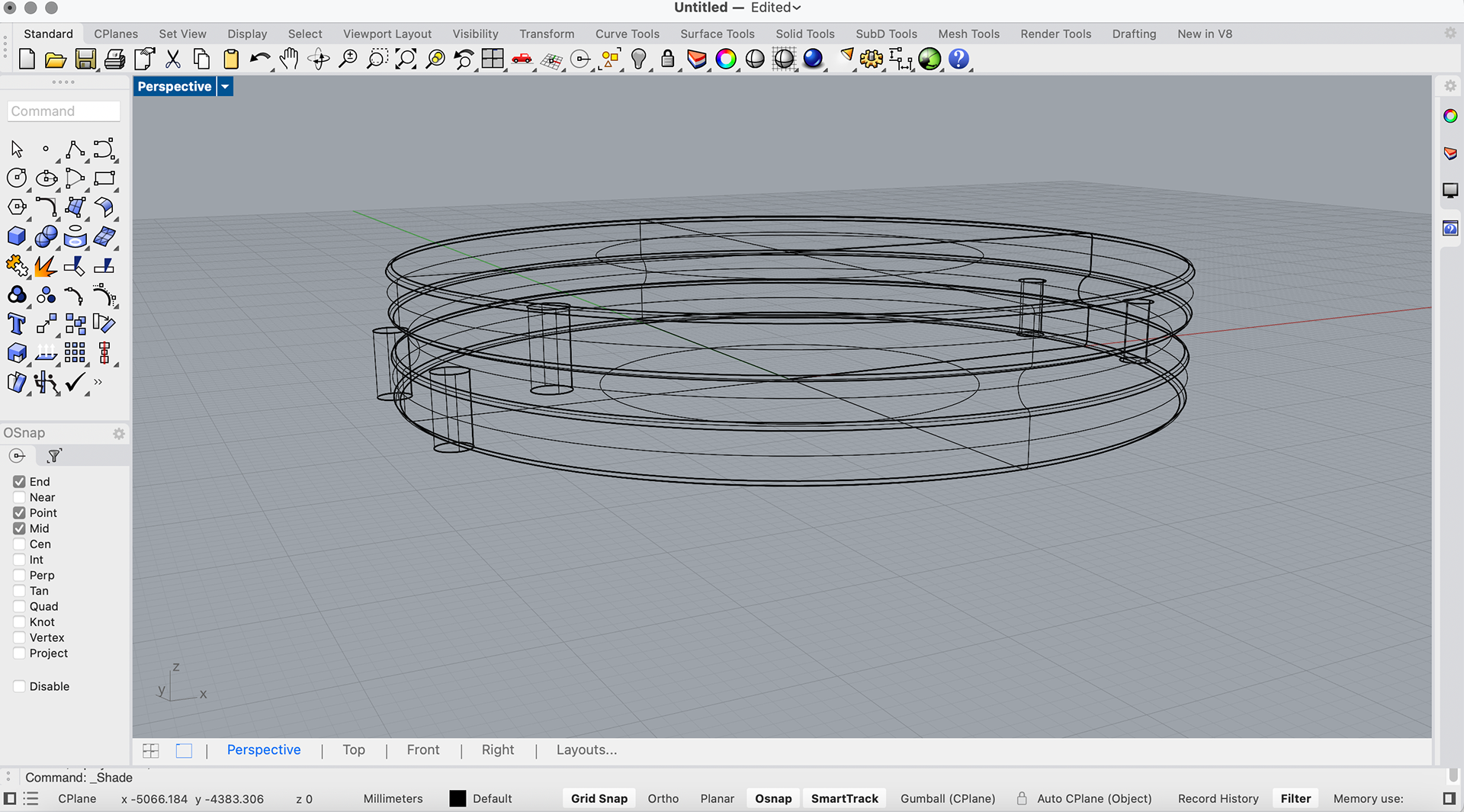
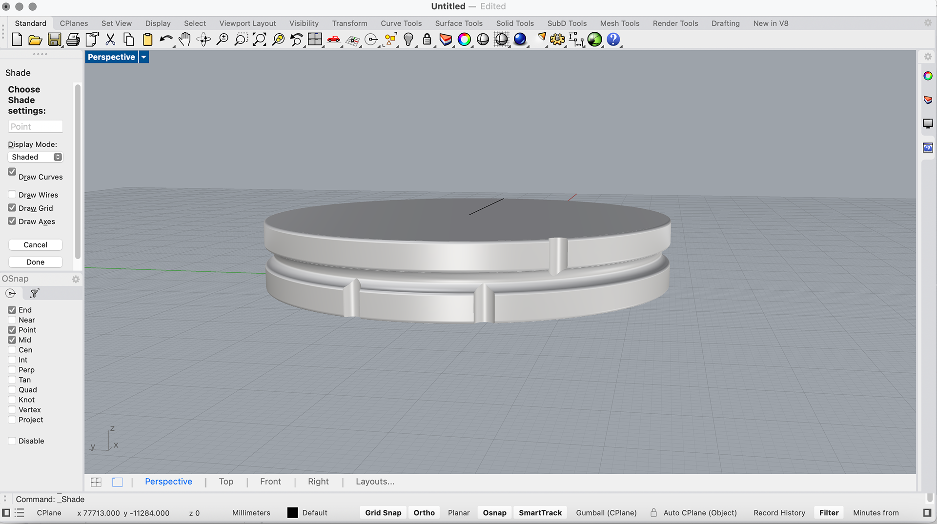
Version 3
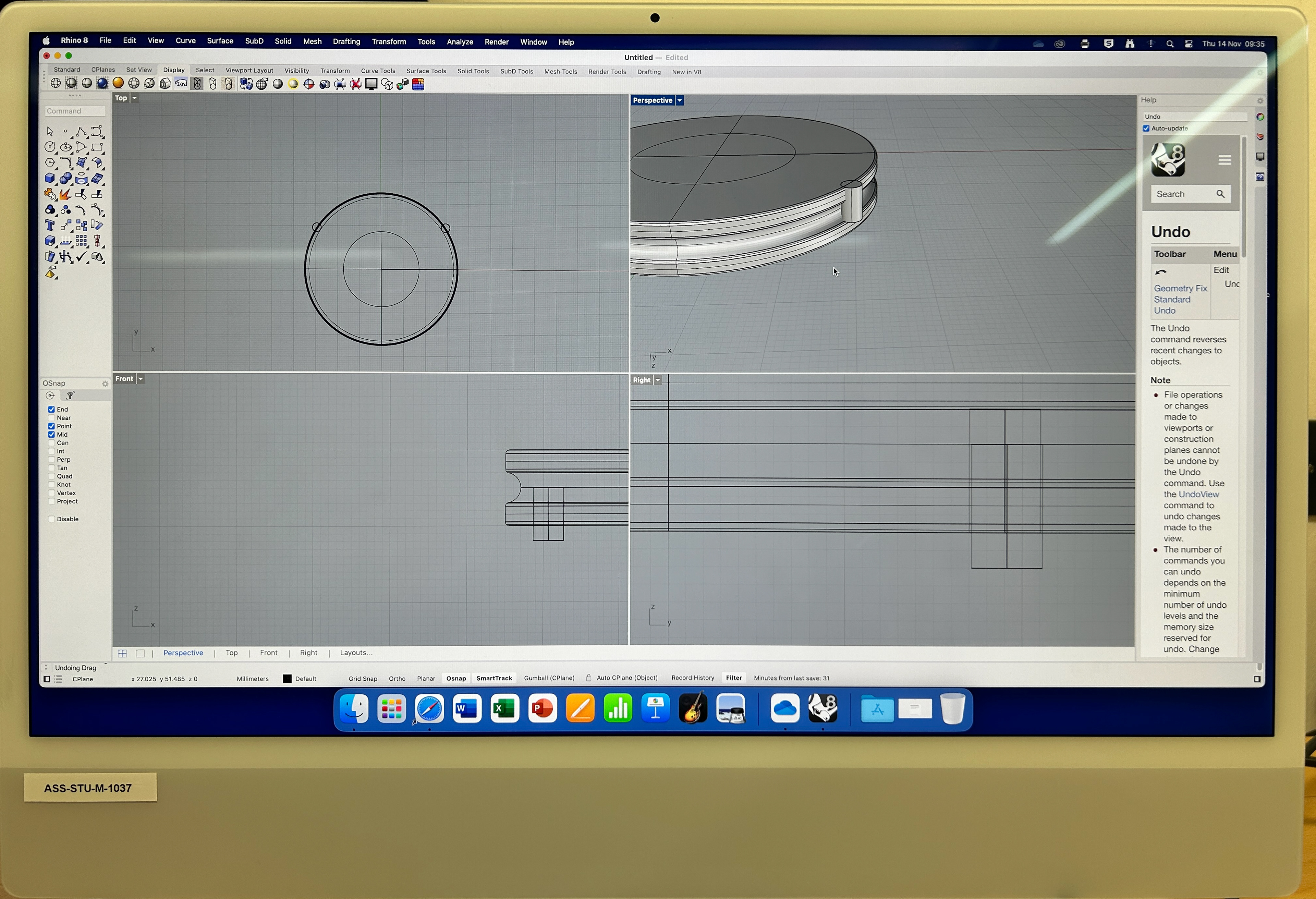
Looking at the tests I had just printed, I realised that I wanted the samples to be thicker, so I created a simple design in Rhino that was 10mm thick rather than 8mm. I also attempted to add the prongs to hold the resin down, however, I then realised that I did not need prongs in the first place. This was because the tension of the two pieces of wire should secure the bacteria sample into place, so I deleted these and printed my thicker sample. I repeated these steps for another sample that was 12mm thick as well, which I preferred out of all of them. This was because it left enough room for the bacteria to be sufficiently covered by a layer of resin.
8mm vs 10mm

10mm vs 12mm
Version 4
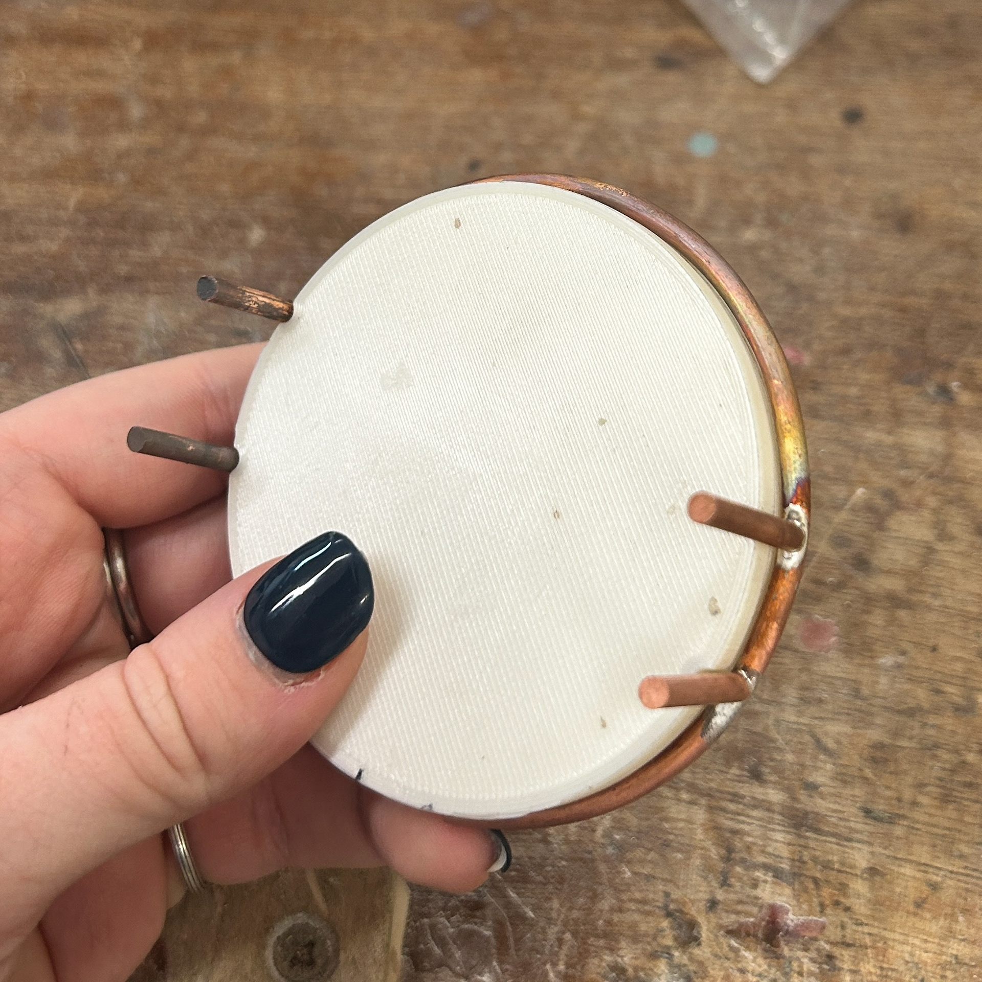
After printing version 3 I realised that I still needed the indents, as this wire extending from the centre would then hold the brooch mechanisms on the back, and the black onyx that will be sitting on the top. I then went back to Rhino and redesigned my dish with my new measurements and printed a new version. I also made sure that the width between the brooch mechanism was slightly shorter at the end where the pins would go, as this would allow for tension.
Unfortunately, the print had some inconsistencies in the surface finish, even after moving the print's position in Cura so I had to reprint this.
3D Printed Stamp Idea
20th November 2024
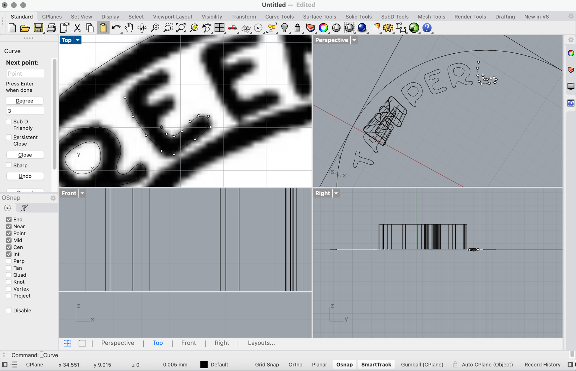
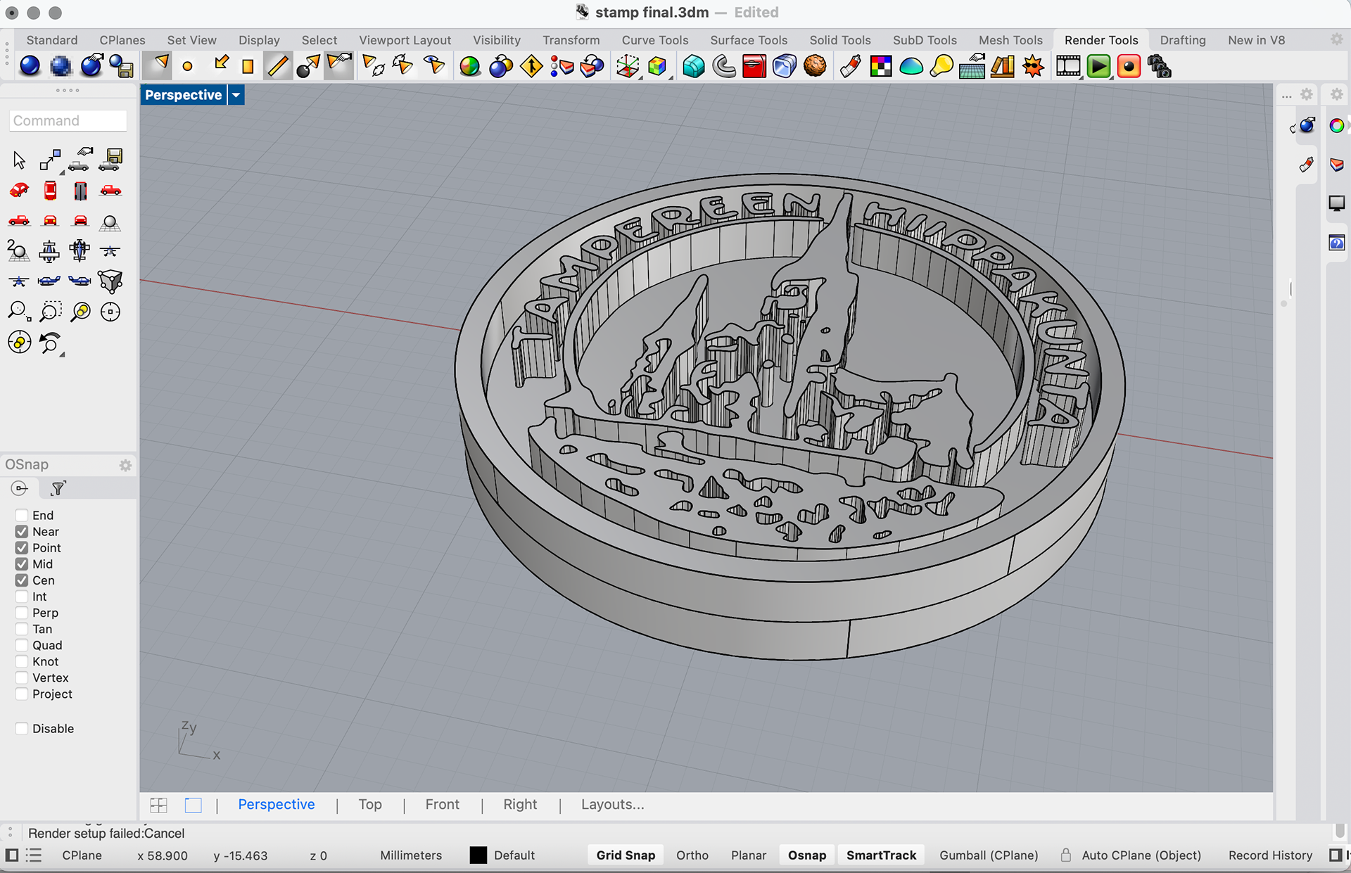
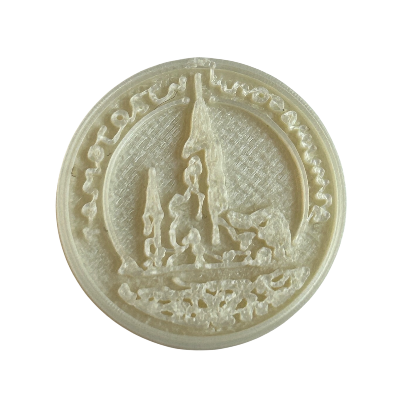
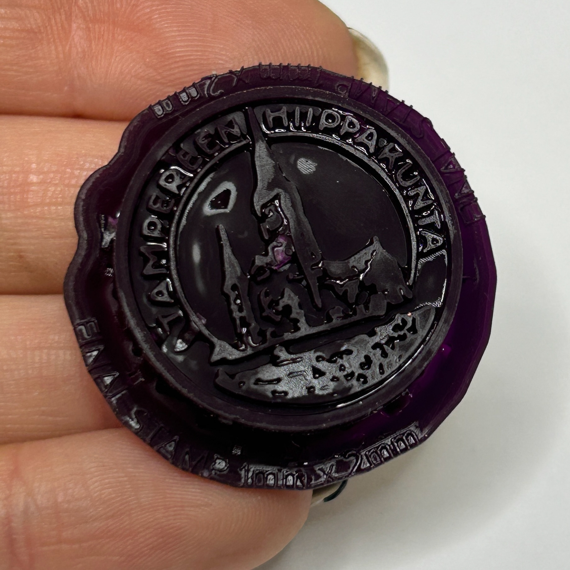
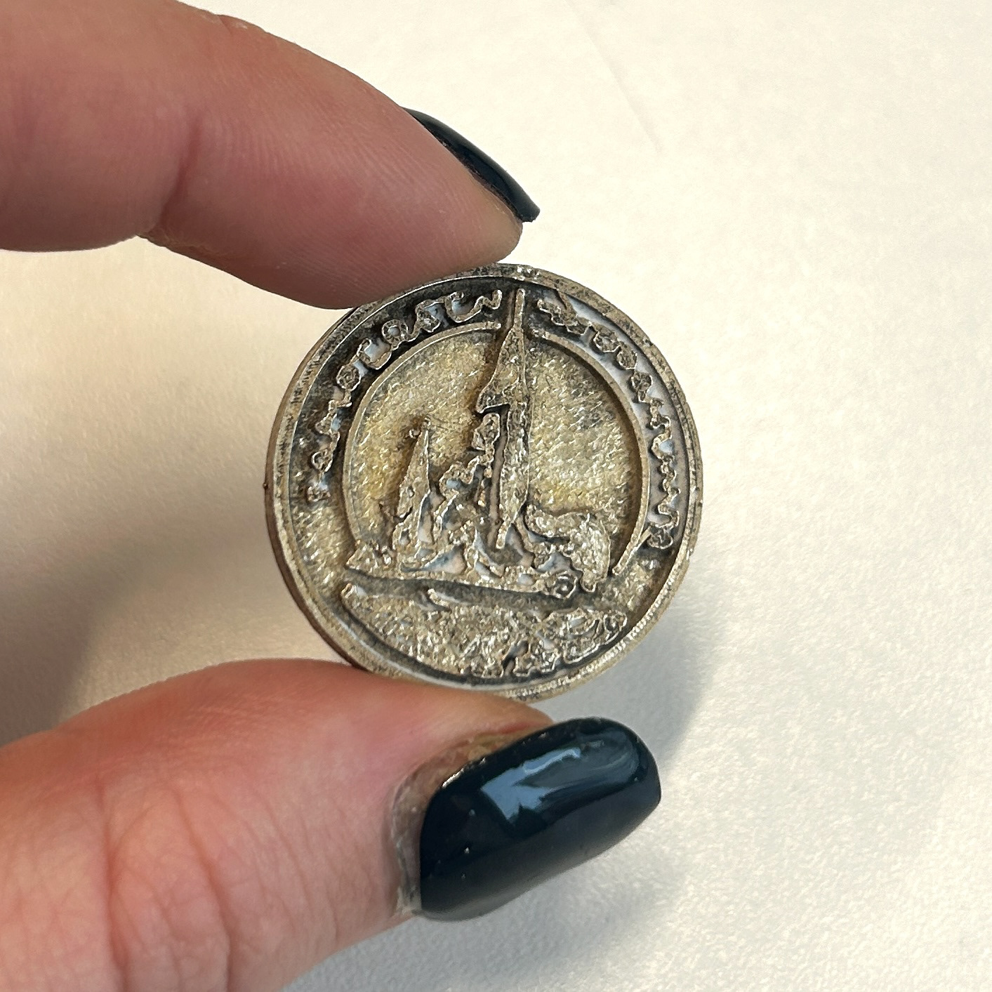
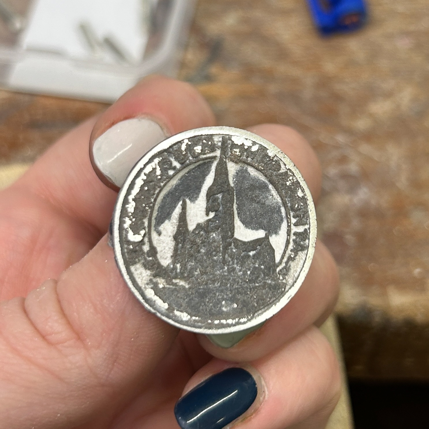
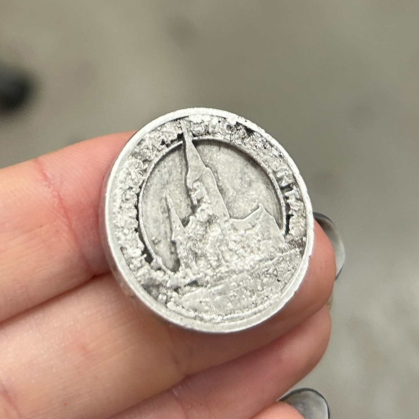
While using Rhino, I questioned what other ways I could incorporate 3D printing into my work. In my original final design, I included an enamelled circle that would be inspired by the stamp on my grandparent's wedding certificate, which is of the church where they got married in Pälkäne, Finland. I decided that I would attempt to redesign this idea and instead use a 3D-printed stamp that I could then cast in solid 925 silver.
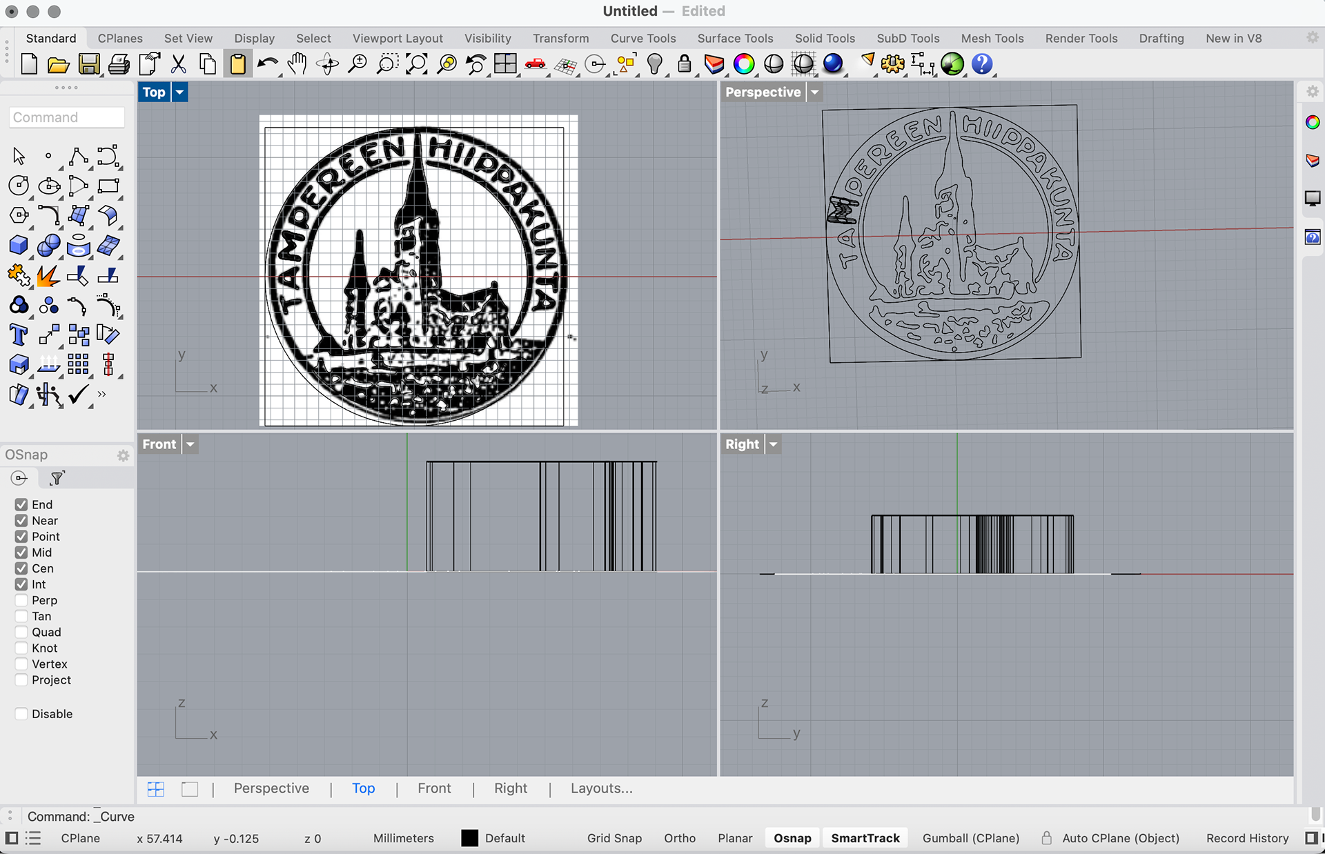
I first attempted to make an outline in Adobe Illustrator using the trace image function, import this an an SVG file into Rhino, scale, and then extrude the image. However, this did not work. This was because of the quality of the image and the stamp having too many lines and confusing Illustrator. Instead, I had to import the picture into Rhino, and then use the curve tool to draw the parts that I wanted to extrude. While this was time-consuming, I did work. I extruded the parts by 4mm and then added a 1mm backing. I realised that the 4mm height was too high for this, so I first tested this with a 3mm extrusion and a 1mm backing, then printed this for testing. The idea was that this would then be printed in wax by Print City for lost wax casting.
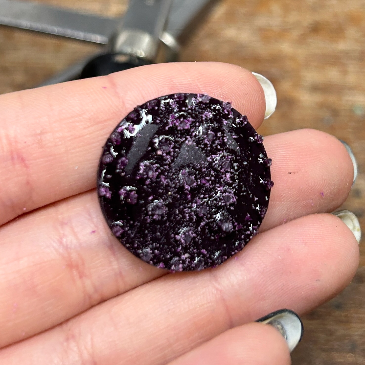
After printing this, I decided to test a couple more heights of the extrustion and the backing, to find the right balance. I had originally intended to enamel the spaces between the extruded parts, however after printing I realised how small these parts were and knew that they would melt in the kiln, so this idea was abandoned. Instead, I might experiment with a black patina and then file and polish the top, resulting in a higher contrast and exaggeration of the detailing.
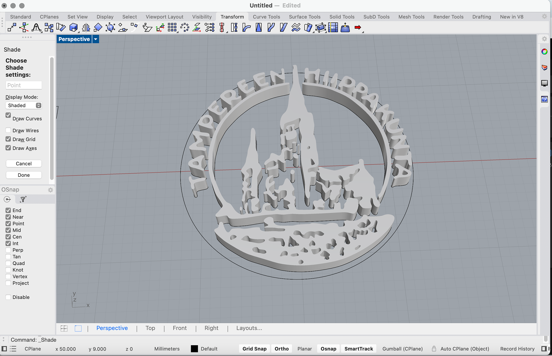
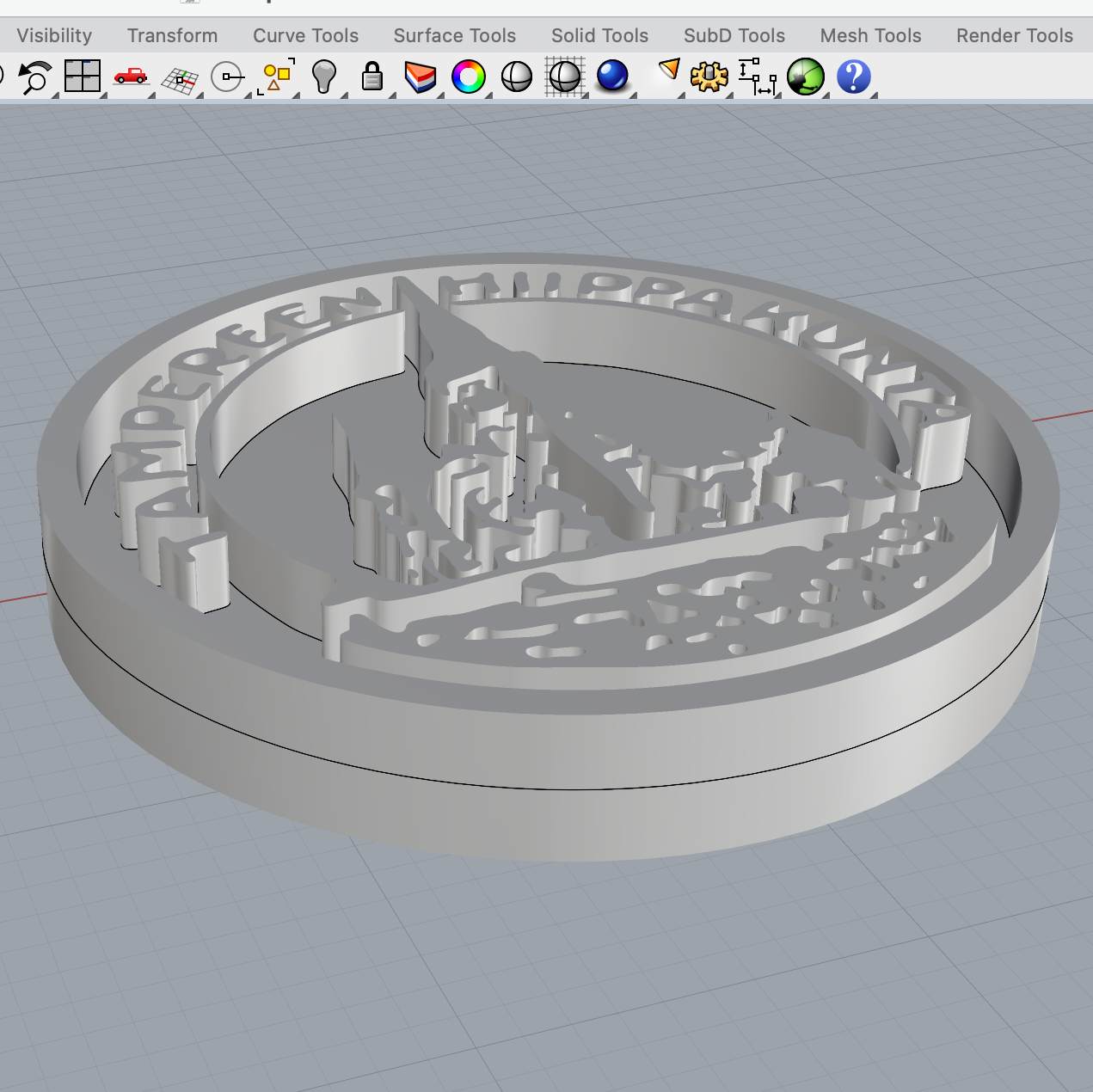

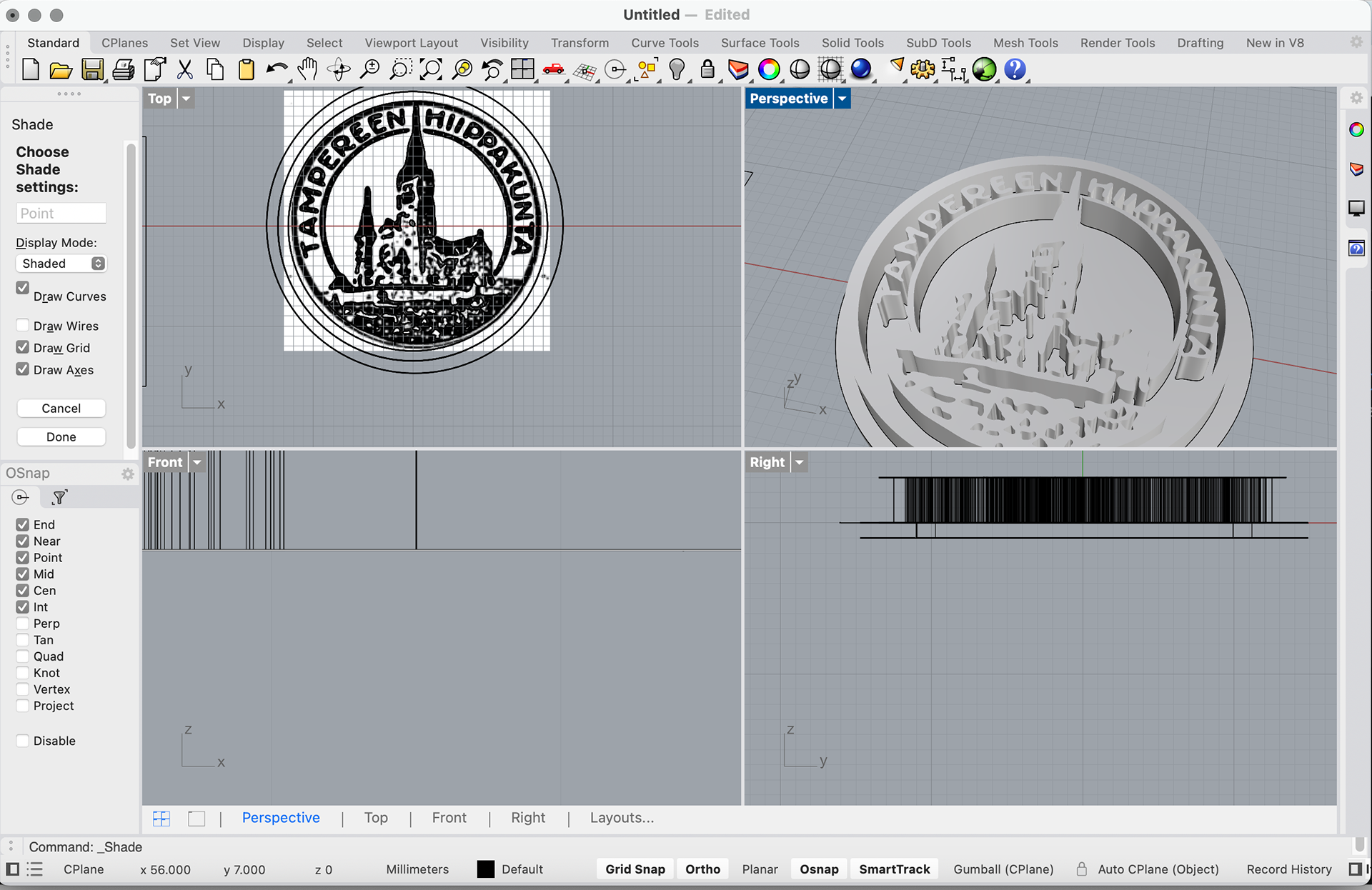
Rhino Render
My final iteration is a 1mm extrusion with a 2mm base. I felt as if this was the most balanced out of the samples I made and looked the most refined. I also removed the outer circle that I had added, and instead made the edge of the stamp the edge of the piece, giving it a more seamless look.
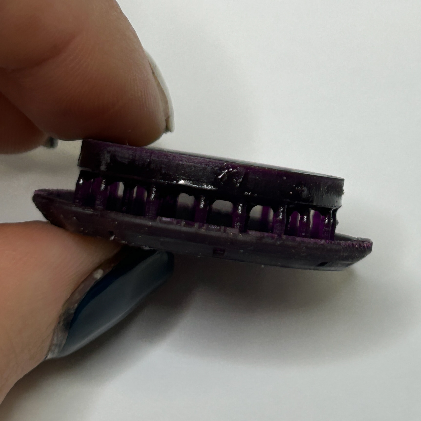
Height Tests


3mm extrusion, 1mm backing
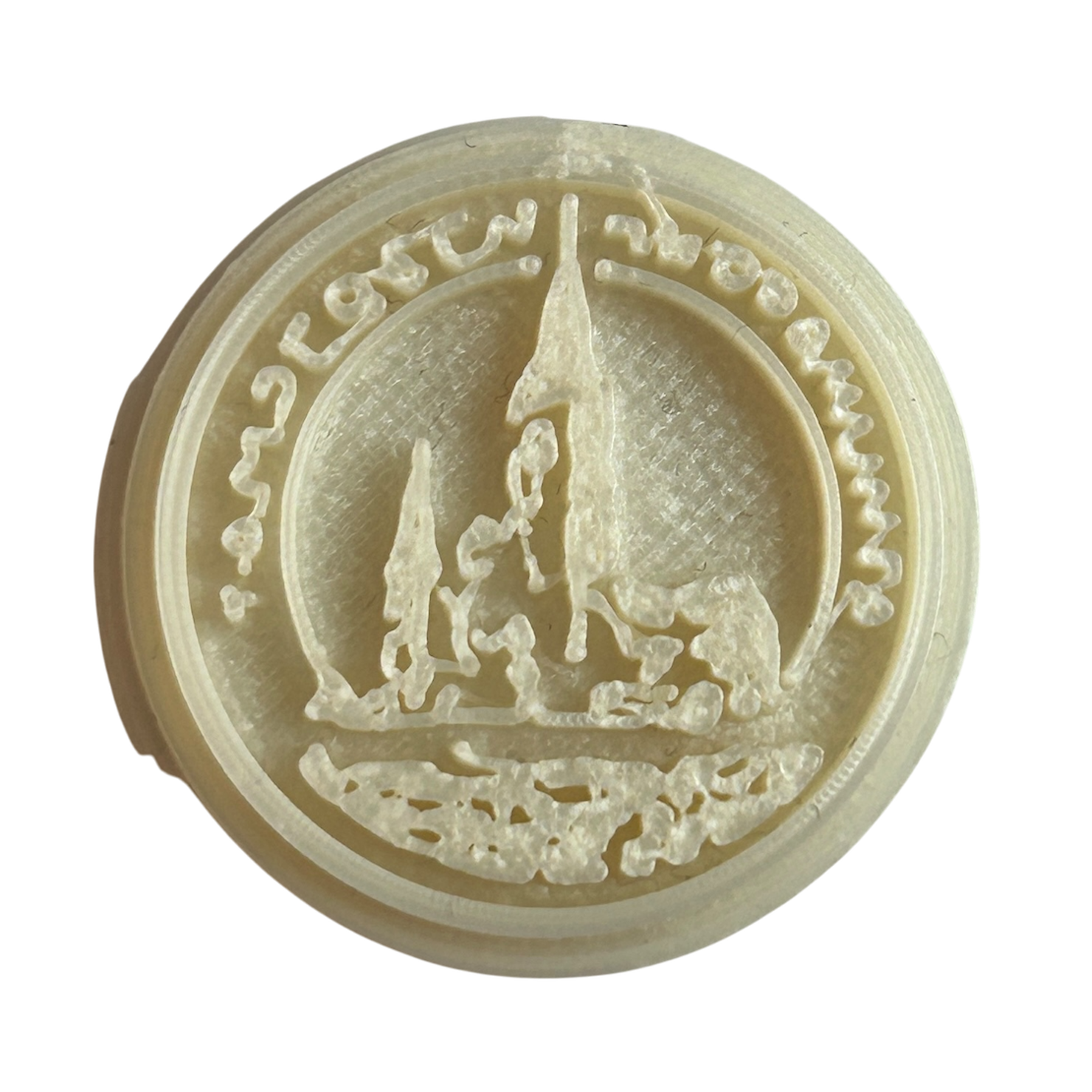
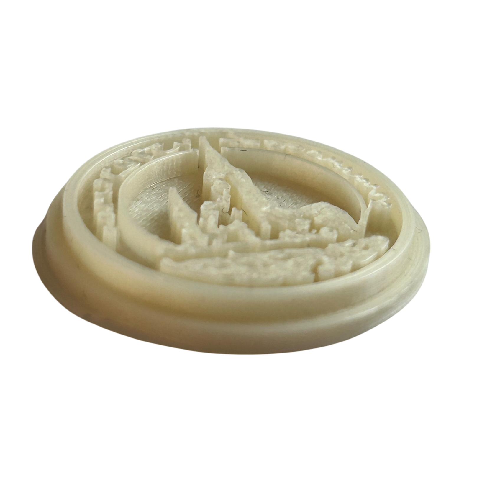
2mm extrusion, 2mm backing

1mm extrusion, 2mm backing
3D Printed Wax
26th November 2024
After settling on the 1mm extrusion with a 2mm base, I sent this to Print City to be printed in Formlabs castable wax resin. This material with the printers can produce a much higher resolution, resting in a more detailed cast. When I received this print back, I had to remove the supports with a piercing saw, as snips could not reach the inside supports, I then filed this back as much as possible to help reduce the need for clean-up post-casting.
I was incredibly pleased with the outcome of this, and it has made me more motivated to become confident using Rhino so I create more pieces using this method.
Casting
28th November 2024
Brass Casting
I decided to 3D print two of the stamps in the polycast material, and cast these in brass to see the difference between the resolution of the Ultimaker using Polycast and the printers at Print City using the wax resin material.
I realised that I actually really liked the version made with PolyCast, as it made the text from the stamp look almost handwritten. Although the resolution wasn’t as high, I still liked the overall outcome.
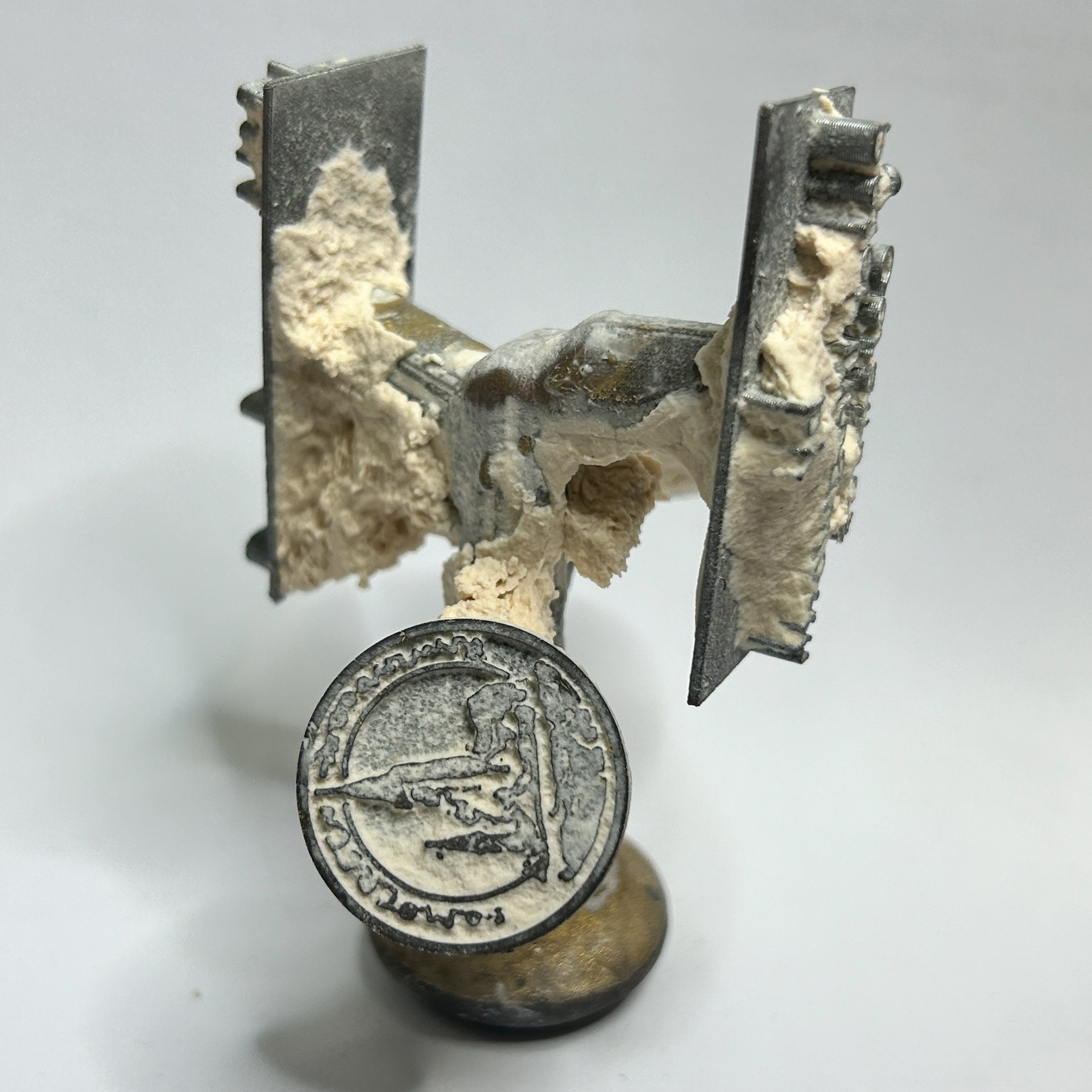
Silver Casting
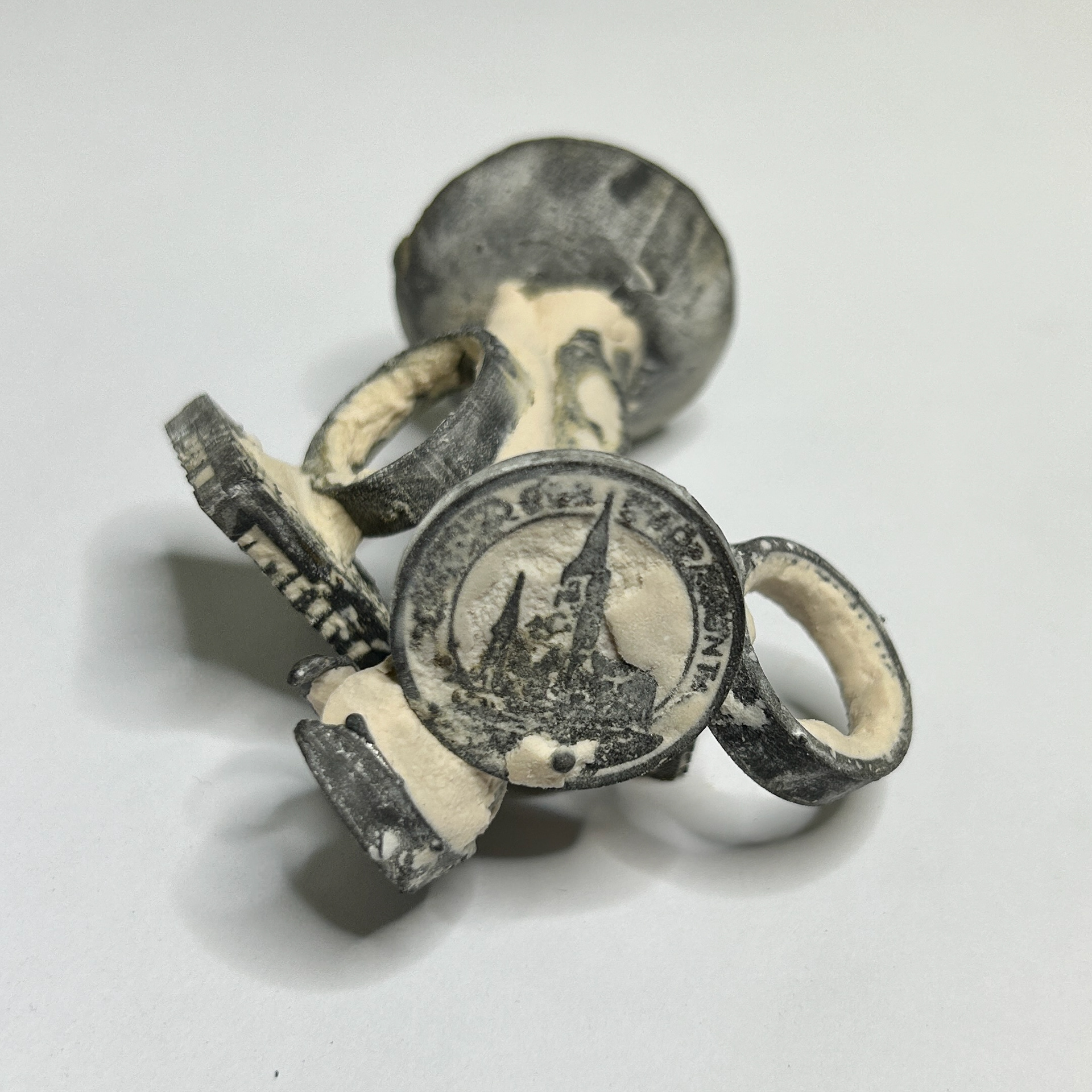
The above shows the results of casting the 3D-printed wax using silver. Unfortunately, the cast did not turn out as well as I had hoped. The plaster did not reach all of the small details and therefore, lots of the detail was not captured correctly. This could have been due to the consistency of the plaster, or the placement onto the wax tree. In hindsight, I should have placed the stamp more vertically rather than horizontally, as then the plaster would have had a better chance of filling all of the details as the plaster filled up in the crucible. Thankfully Oonah's rings were not so affected by this which makes me think that the main problem was the placement of my stamp. While this is annoying, I have learnt from my mistakes and will always be more careful when making my wax tree and the plaster with this material.
3D Printed Cottle
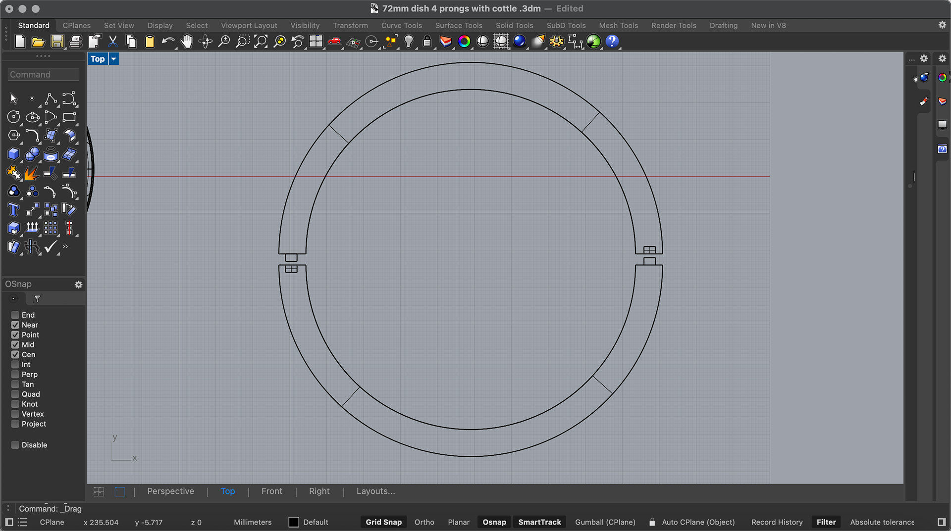
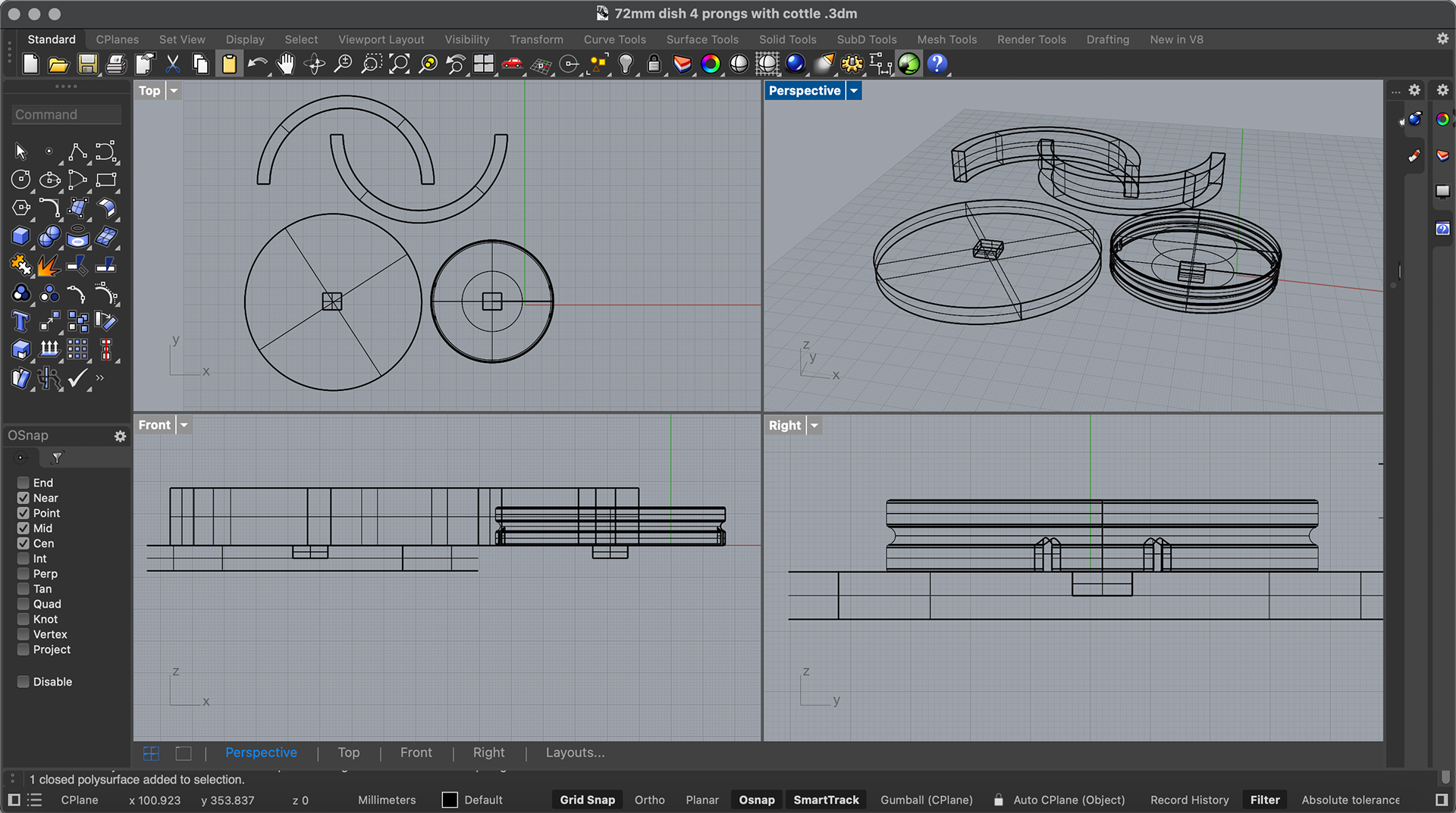
While 3D printing, Geoff suggested that I 3D print the cottle that I will be using for the silicone, as this would allow me to make the custom size that I would need. This would also build my confidence in using CAD and reinforce the idea that I would be making all of my components myself, and customising each piece to my needs, which is a transferrable skill I can use in Synthesis and Resolution and the rest of my practice.
I made this cottle by creating a base underneath my dish and extruding a tube around this. I also added a square positive and negative mechanism on both the base and the petri dish, as well as the cottle. This will help me hold the pieces in place while I tape the seams shut, while also securing the dish into place when the silicone is being poured. I could have kept the base connected to the dish, however, it would have made sanding the edges quite difficult, hence why I have made it so it can be removed.
I have also kept a set of the cottle sides without the positive and negative mechanism, just in case the mechanism is hard to use. This way I can just use tape to hold the sides together.
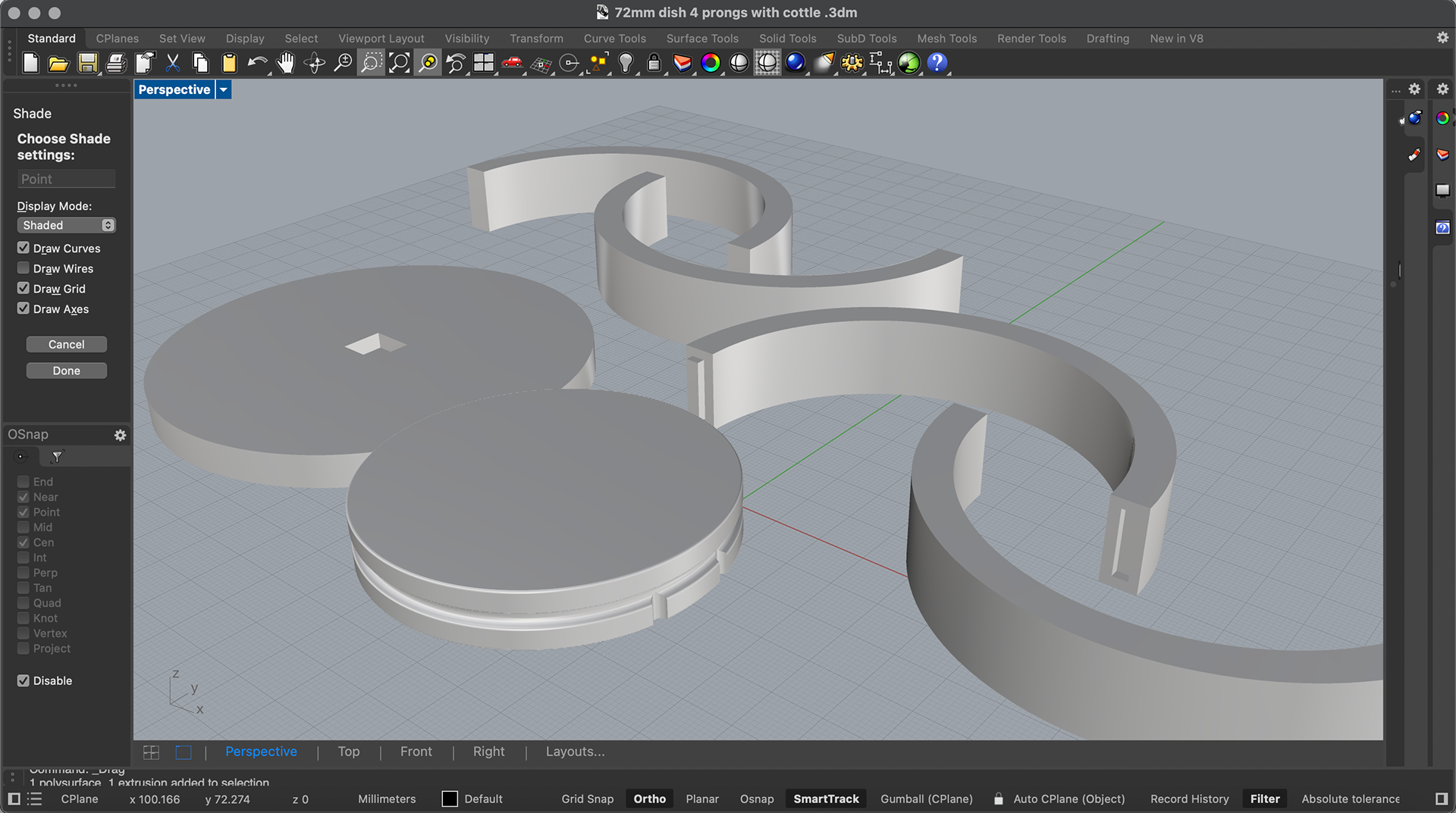
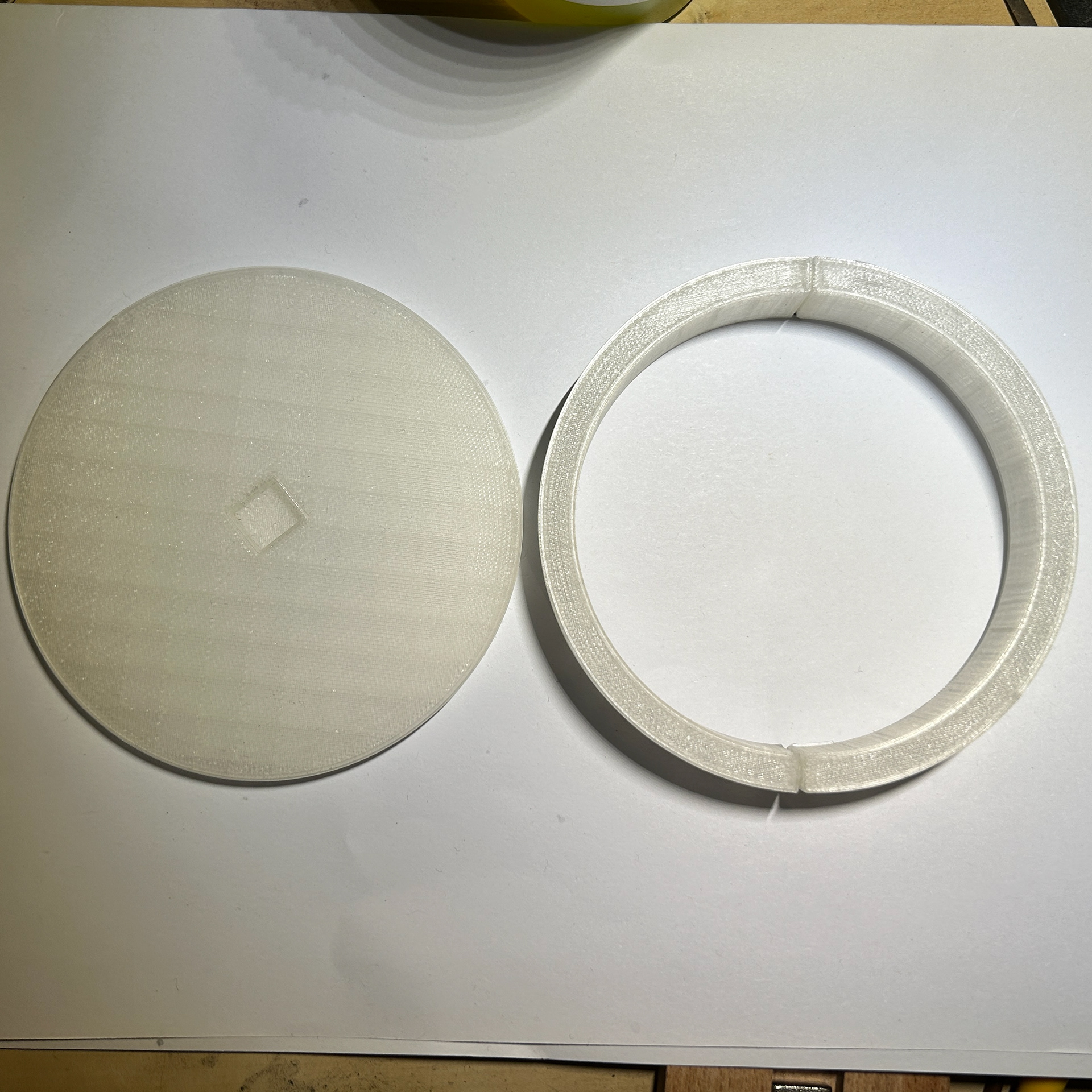
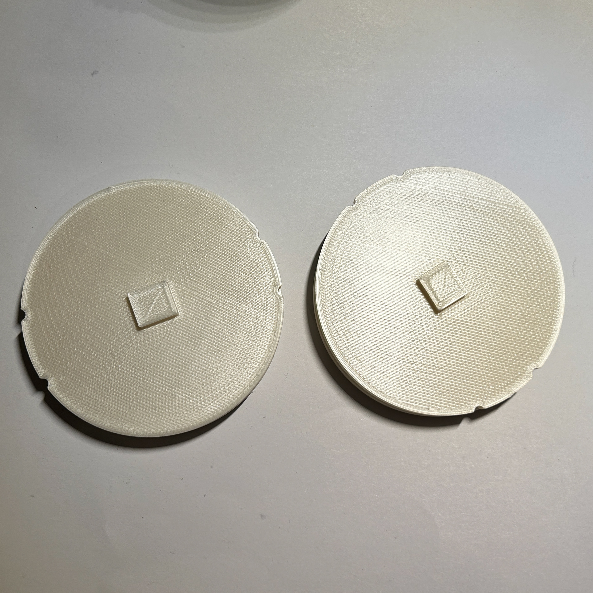
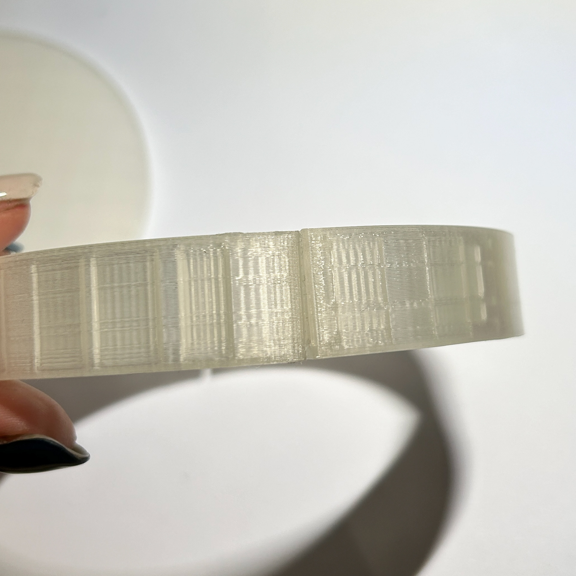
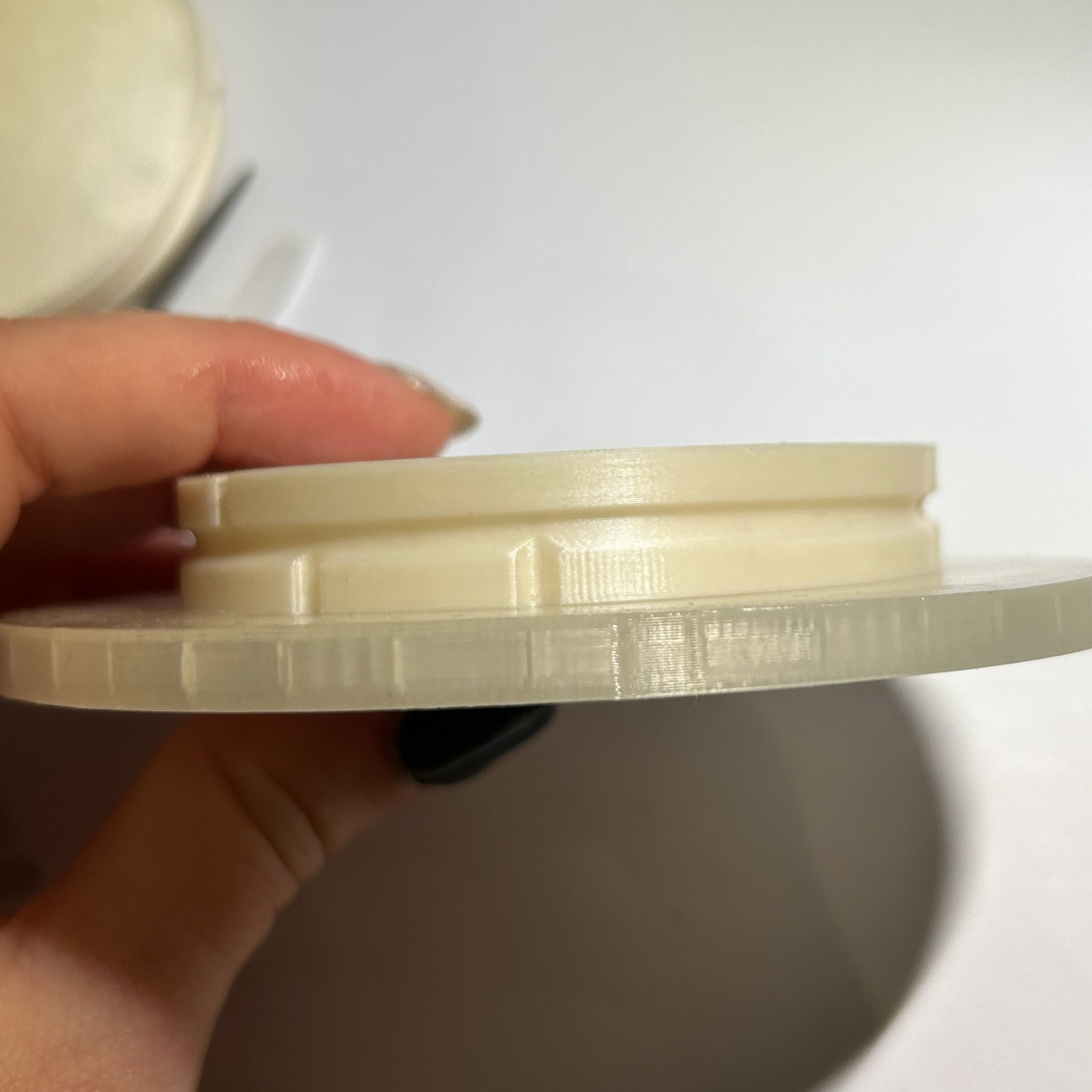
Printed Results
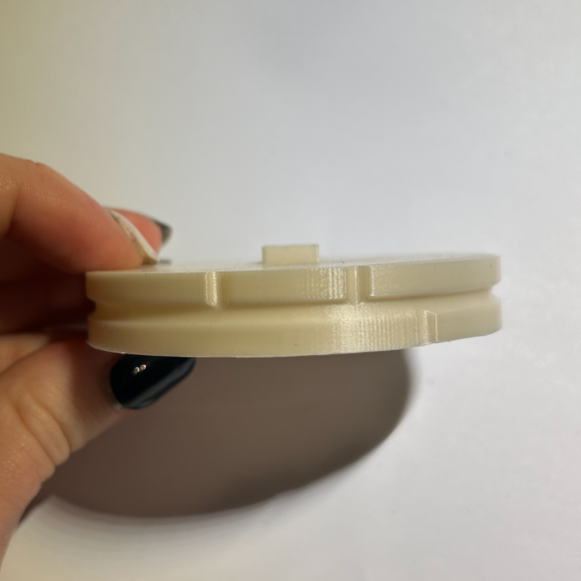
To complete my final design idea, I needed to find the correct mechanism that would hold the two silver wire pieces together. I had ideally liked these to be openable to allow for customisation and interchangeability of the bacteria so I first looked at a barrel catch. This was a new challenge for me since I had never created a mechanism like this before and so pushed me out of my comfort zone and allowed me to explore new techniques.
Barrel Catch
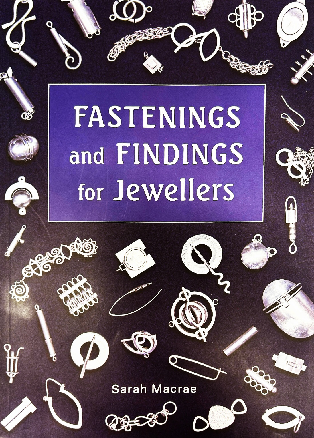
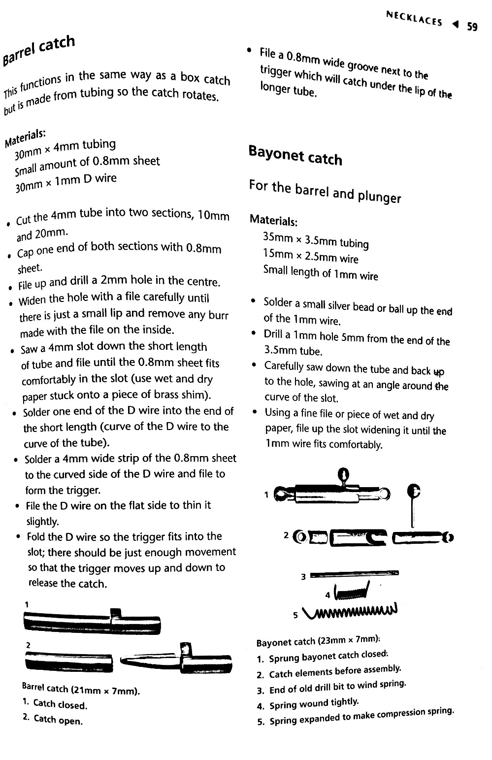
To begin this mechanism, I first looked at some instructions found in the book 'Fastenings and Findings for Jewellers', but to be honest, I found these instructions rather confusing, and so resorted to a Youtube video instead.
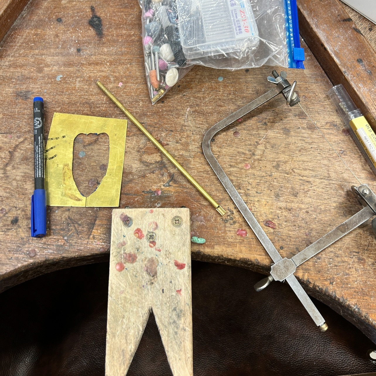

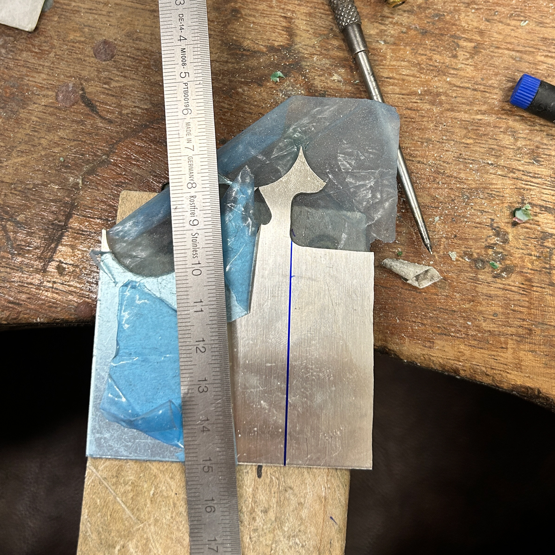
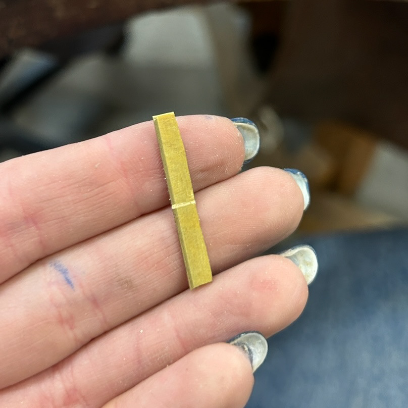
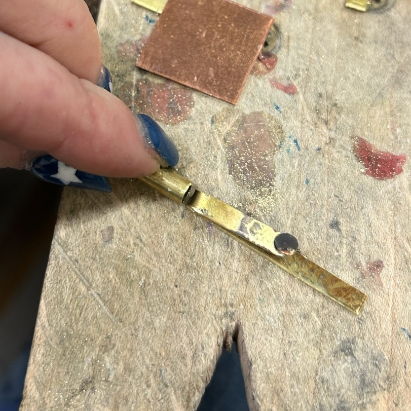
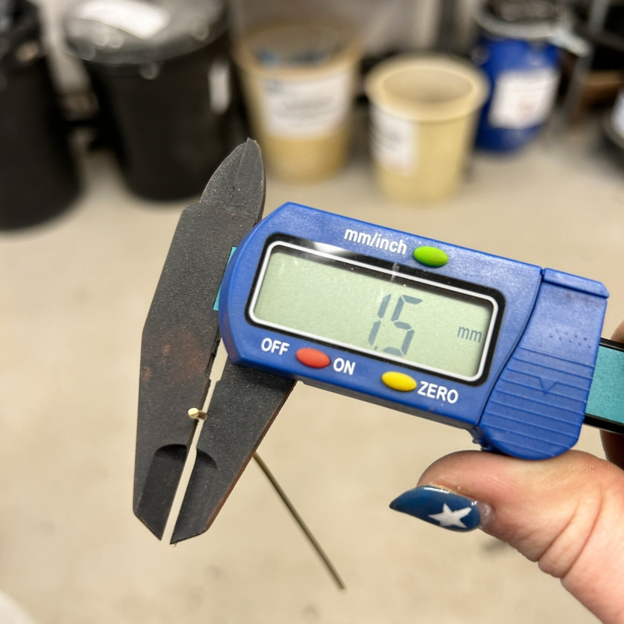
I started by measuring out the length of the catch I wanted to make. I started with 20mm as this seemed like a long enough length for me to hold while sanding and getting familiar with the making process.
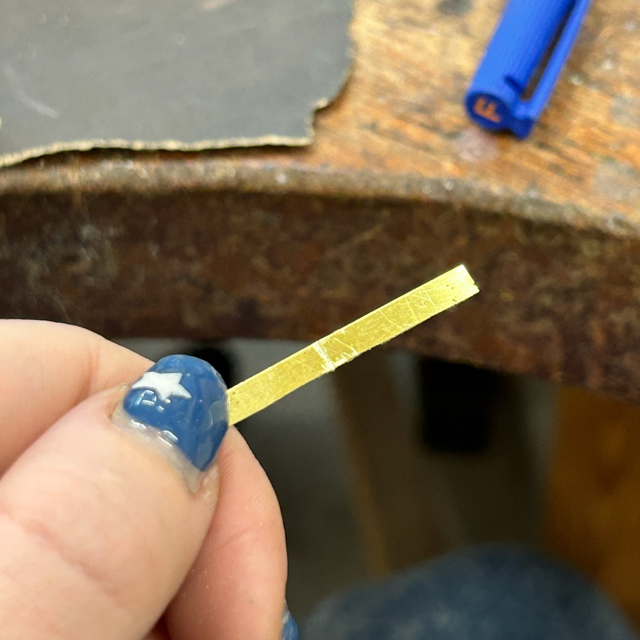
I then used my piercing saw to make a 0.05mm indent into the brass so that it could be folded over on itself easily.

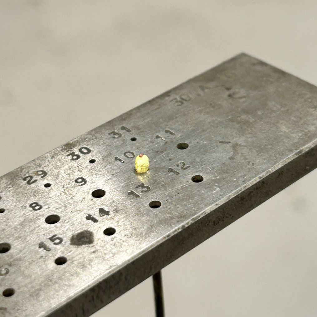
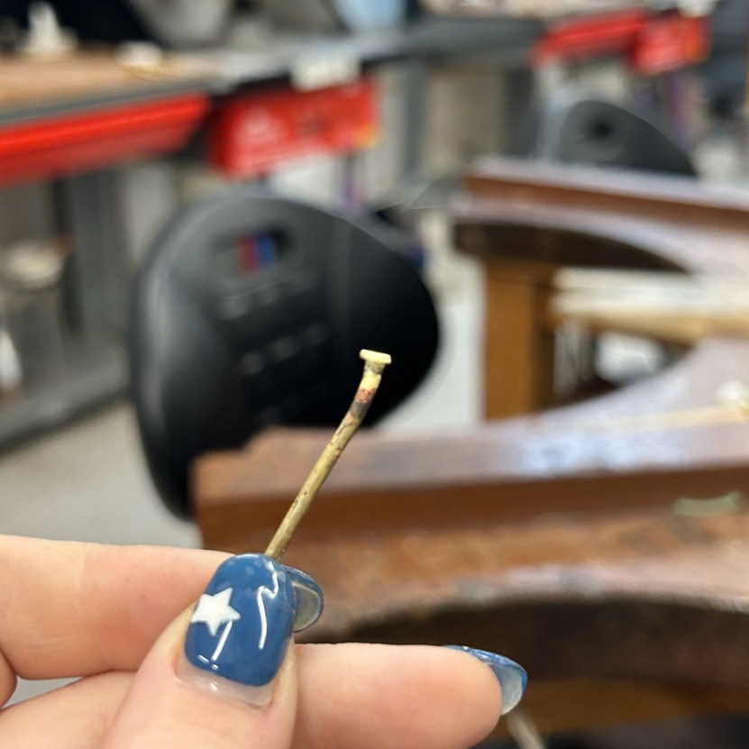
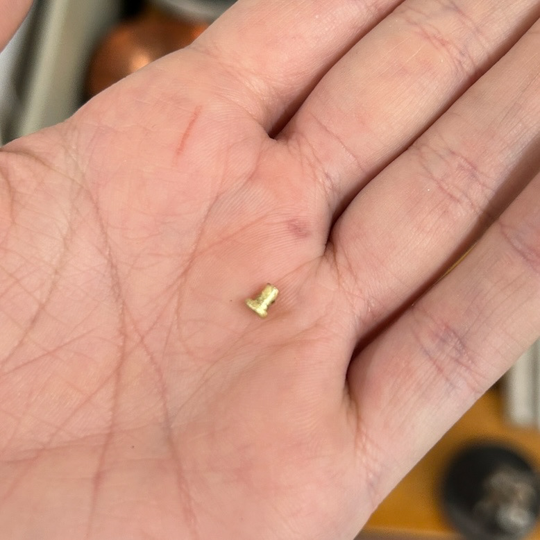
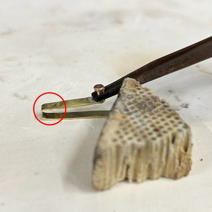
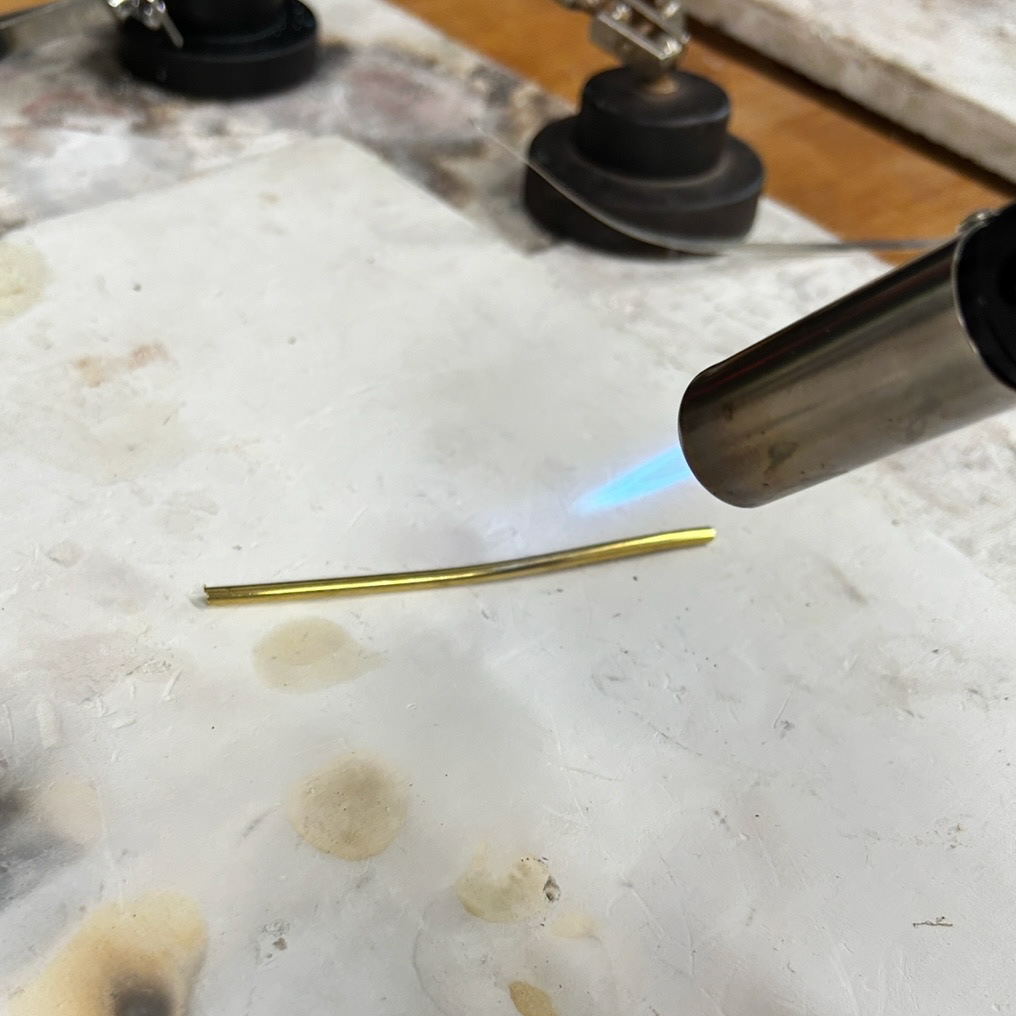
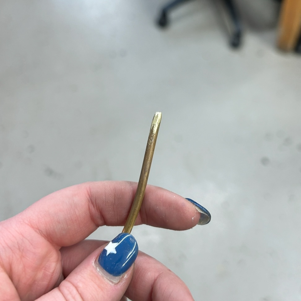
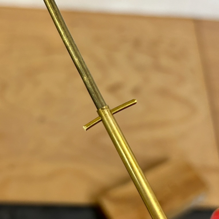
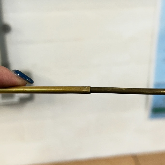
I created a button for the clasp by melting the end of brass tubing into a ball and hammering flat using the drawing tools and a hammer. I then cut this to the desired height to be soldered to the folded brass
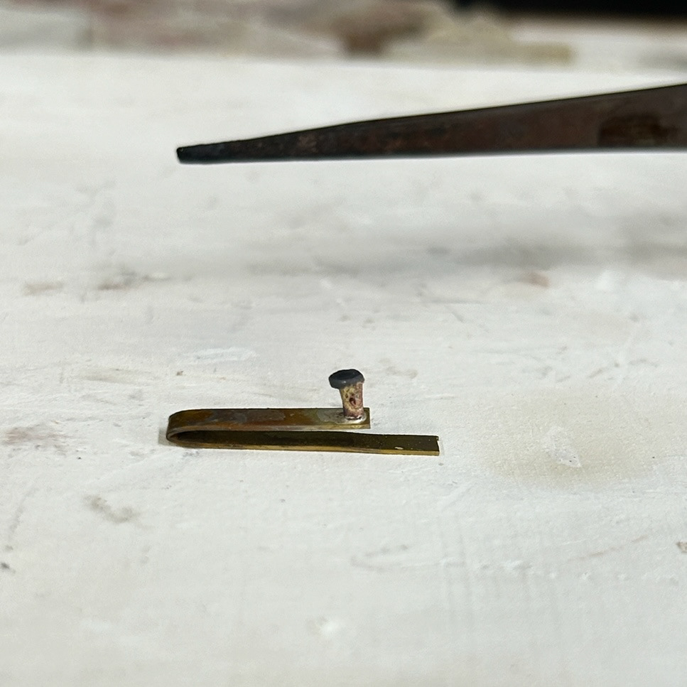
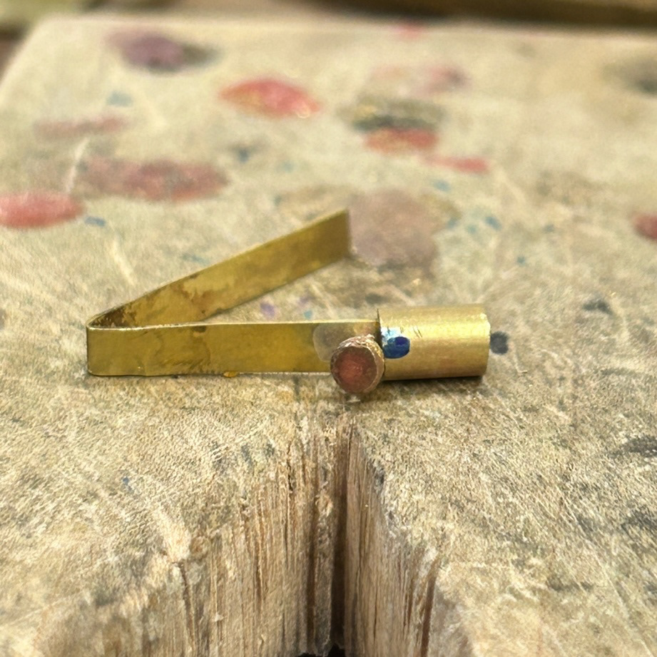
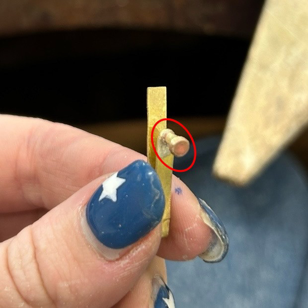
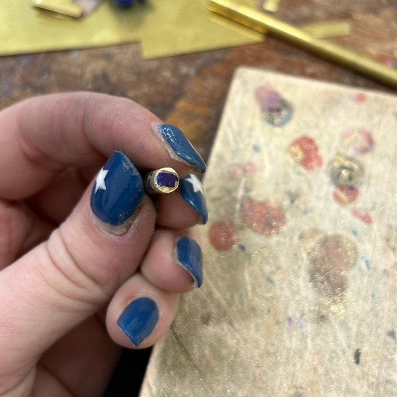
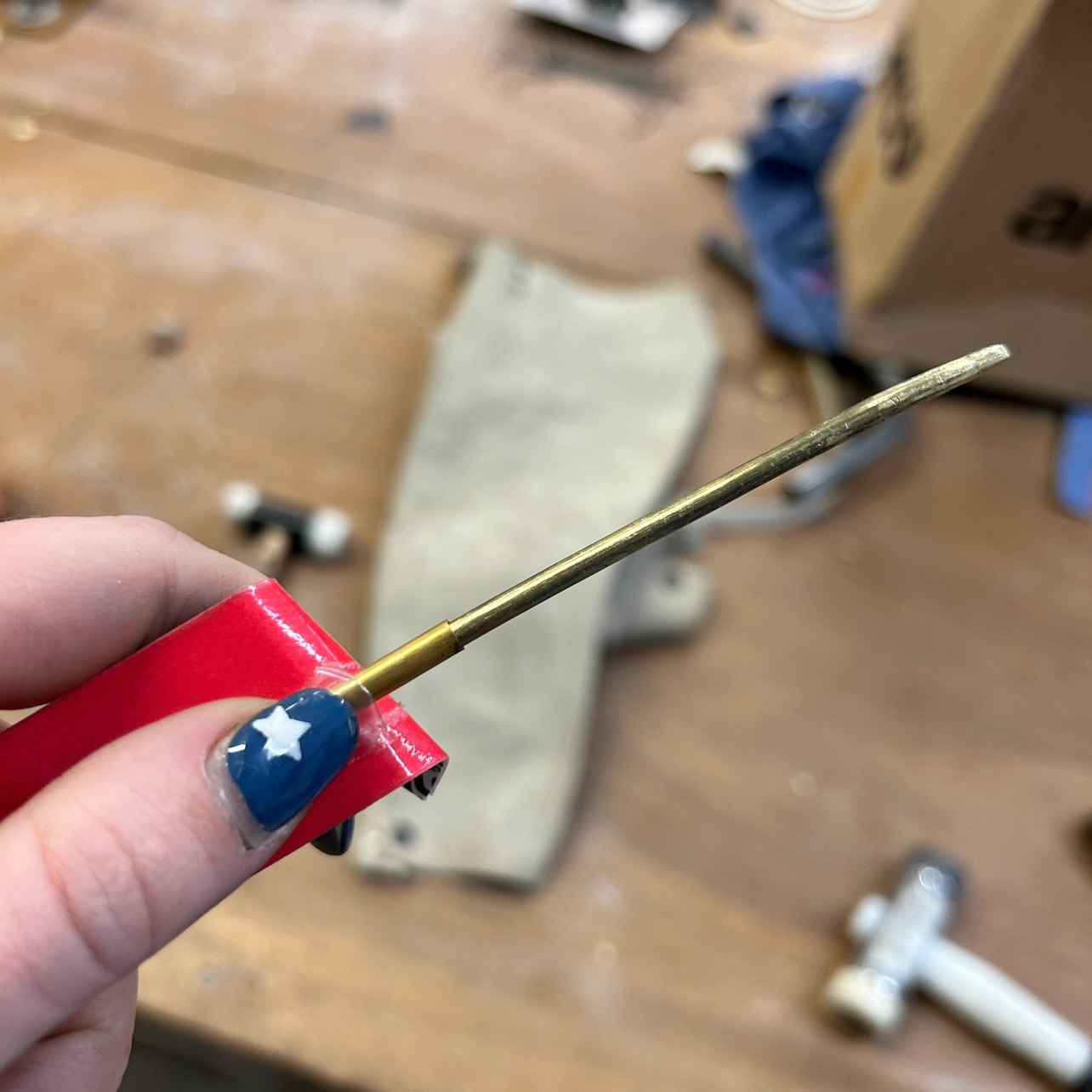
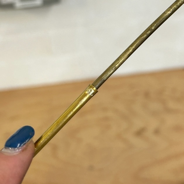
I then soldered this using hard solder and checked the fit to a piece of brass tubing. After checking the fit I then cleaned up the edge around the button to make the mechanism more refined and professional (as circled in picture 4)
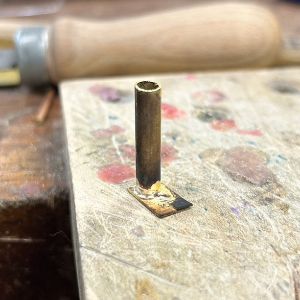
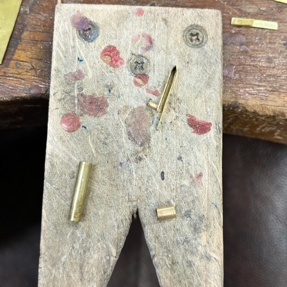
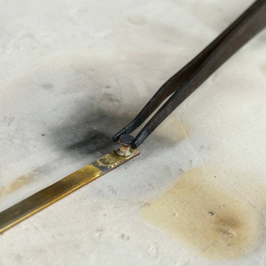
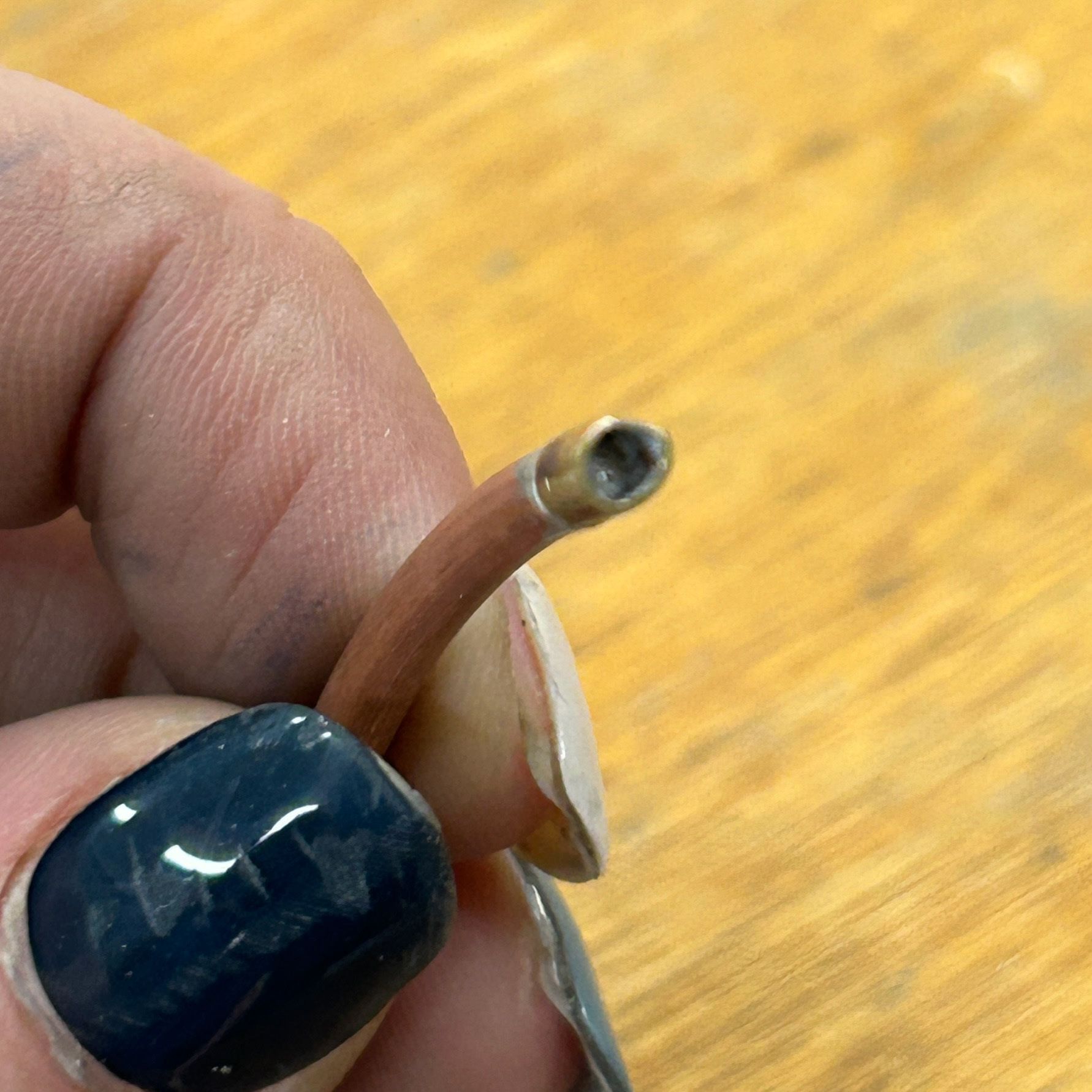
Following that, I soldered close the end of the brass tubing and cleaned up the edges using a piercing saw and files. While I did this I decided to work-harden the folded piece of brass as it was still quite flexible - the exact opposite of what I wanted. To do this, I used the barrel roller as the constant hitting of metal will move the metal molecules from their lattice structure and increase the dislocation density of these molecules, therefore making the metal harder to bend.
However, the barrel roller ended up breaking my piece in half, therefore causing me to repeat the process all over again.
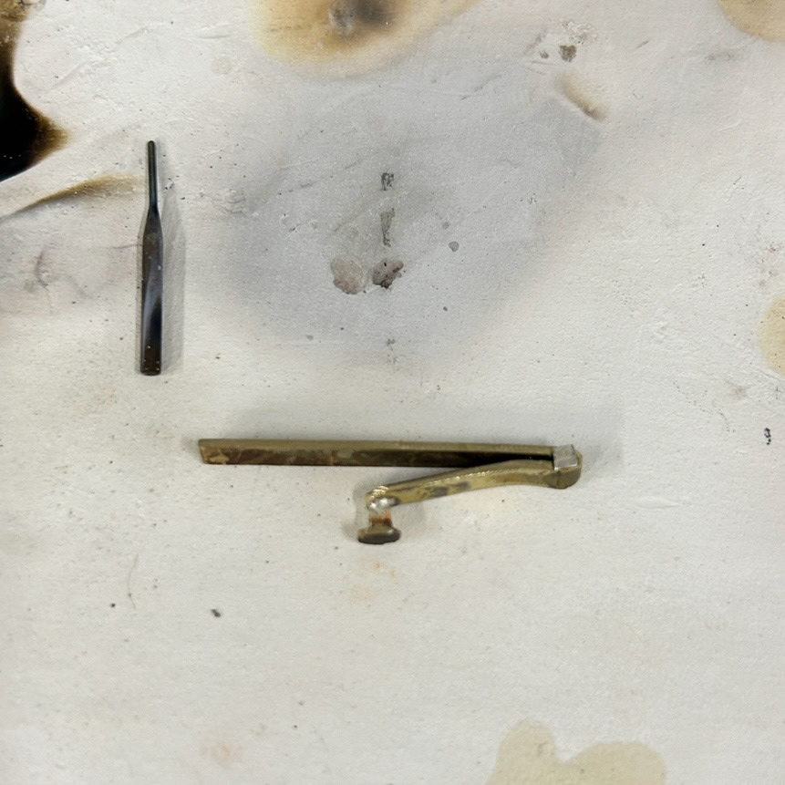
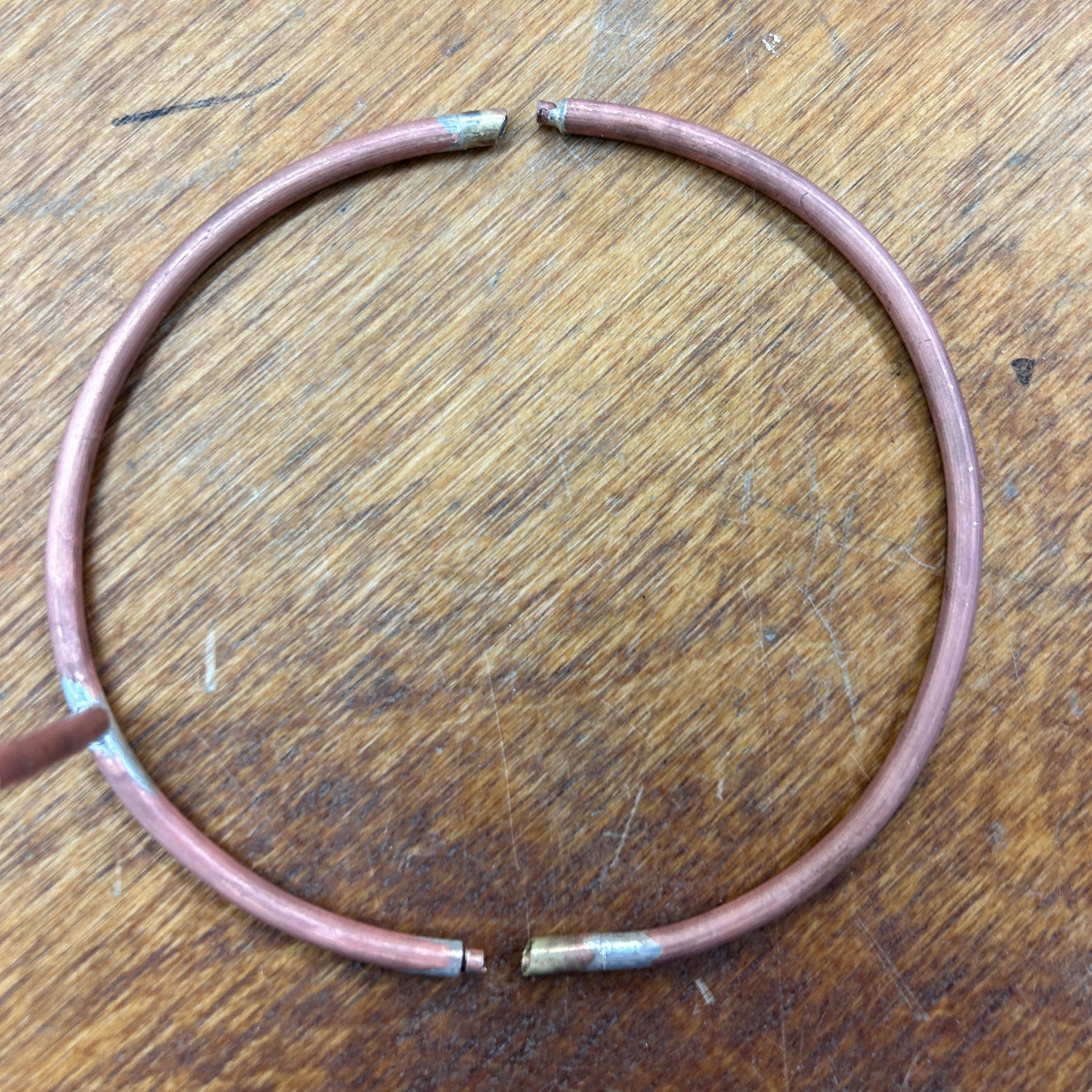
I repeated the steps above to make the catch again, this time using 0.7mm brass instead of 0.5mm. I hoped that using a thicker sheet would help with the structural integrity of the catch, though I did solder the joint to help with this as well.
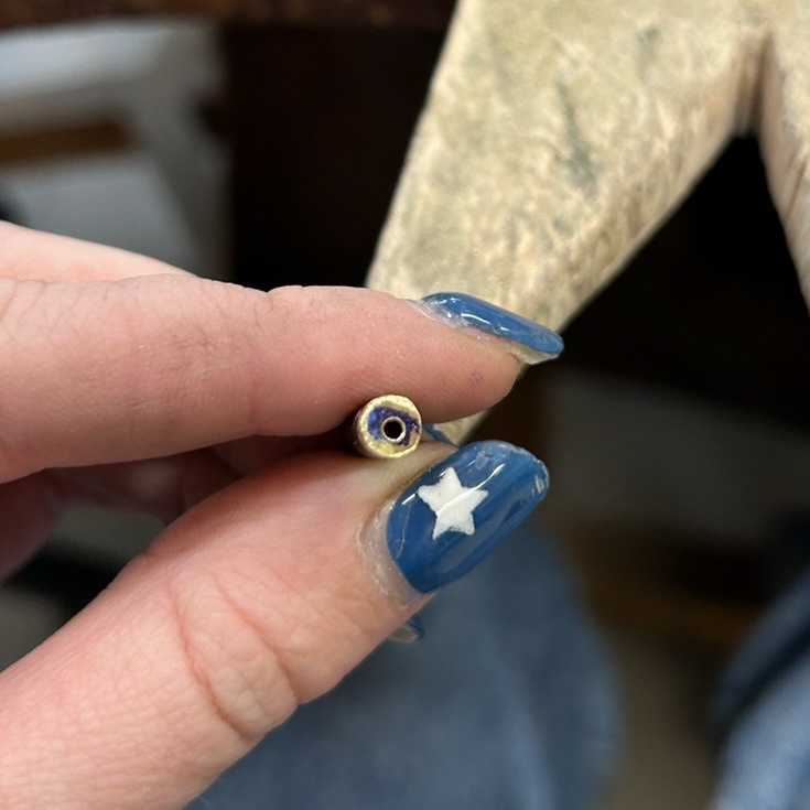
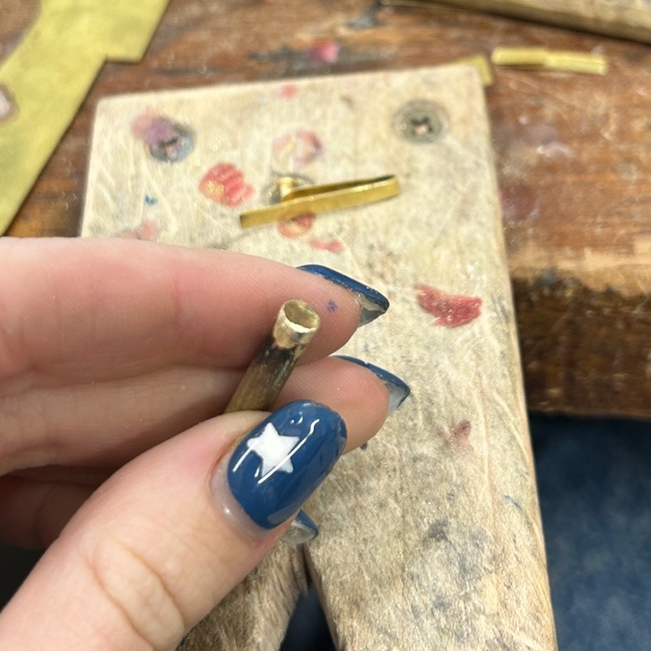
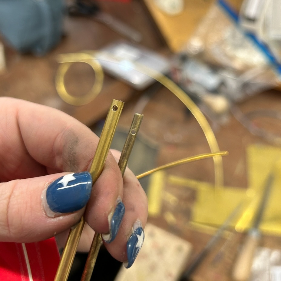
Lastly, I marked out the area that I needed to remove from the end of the brass tube to allow for the catch to be inserted. I used the pillar drill to make the hole and then used a piercing saw and files to remove the rest.
I then tested the mechanism and found that it did not work as expected.
At the time I could not figure out why this was, as I had followed all of the steps from the YouTube video. I thought that it could have possibly been from the metal still being quite soft and therefore not springing back into place when fit inside of the tube. However, looking at this now, I realise that it could possibly be that there needs to be more depth where the catch actually fits within the tube.
By this, I mean that there needs to be a piece of metal that comes down from the top of the tubing and sits into a grove in the bent part of the metal. This is clearly shown in the books' instructions, however, as I did not understand the instructions then I think that is why I had not noticed this. Now I know how to make this catch, I understand the instructions. I need to be realistic on time here, so by the time I perfect this mechanism, it will most likely be too late in the project to integrate it into my design. From this, I have decided to look into a simpler mechanism. While it may not open like I want it to, creating a modular jewellery aspect, it will function as a way to secure my samples.
Riveting
After my failure with the barrel catch, I decided to test riveting. While this may not be the most complicated mechanism, I know that it would secure and hold the wire together without soldering.
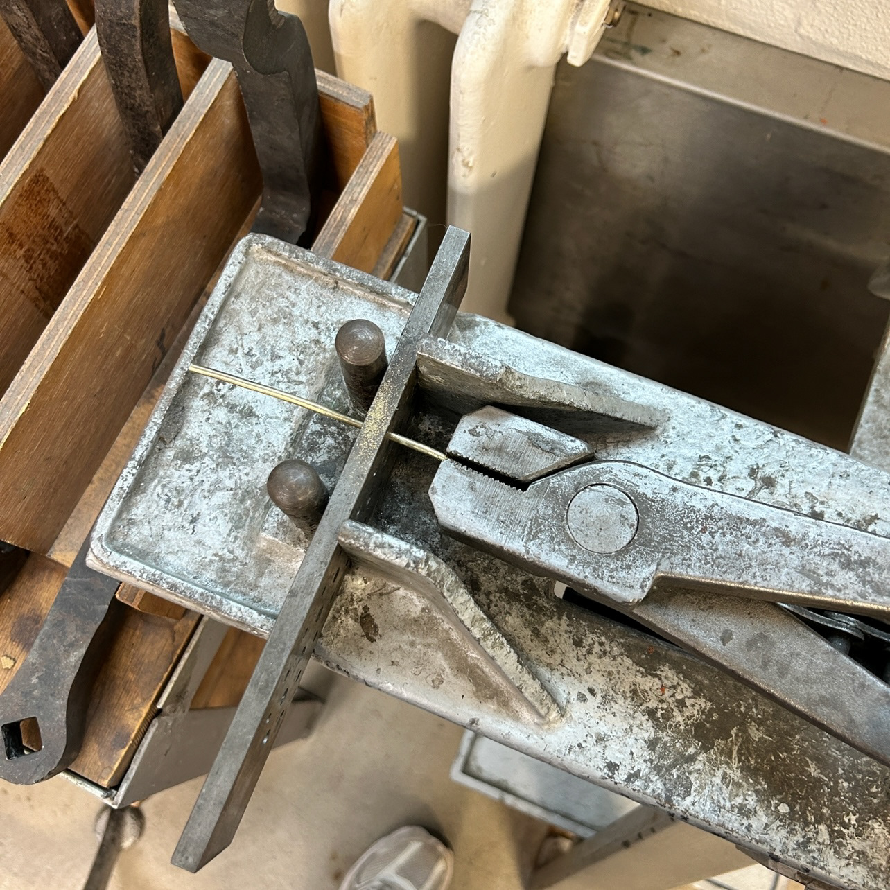
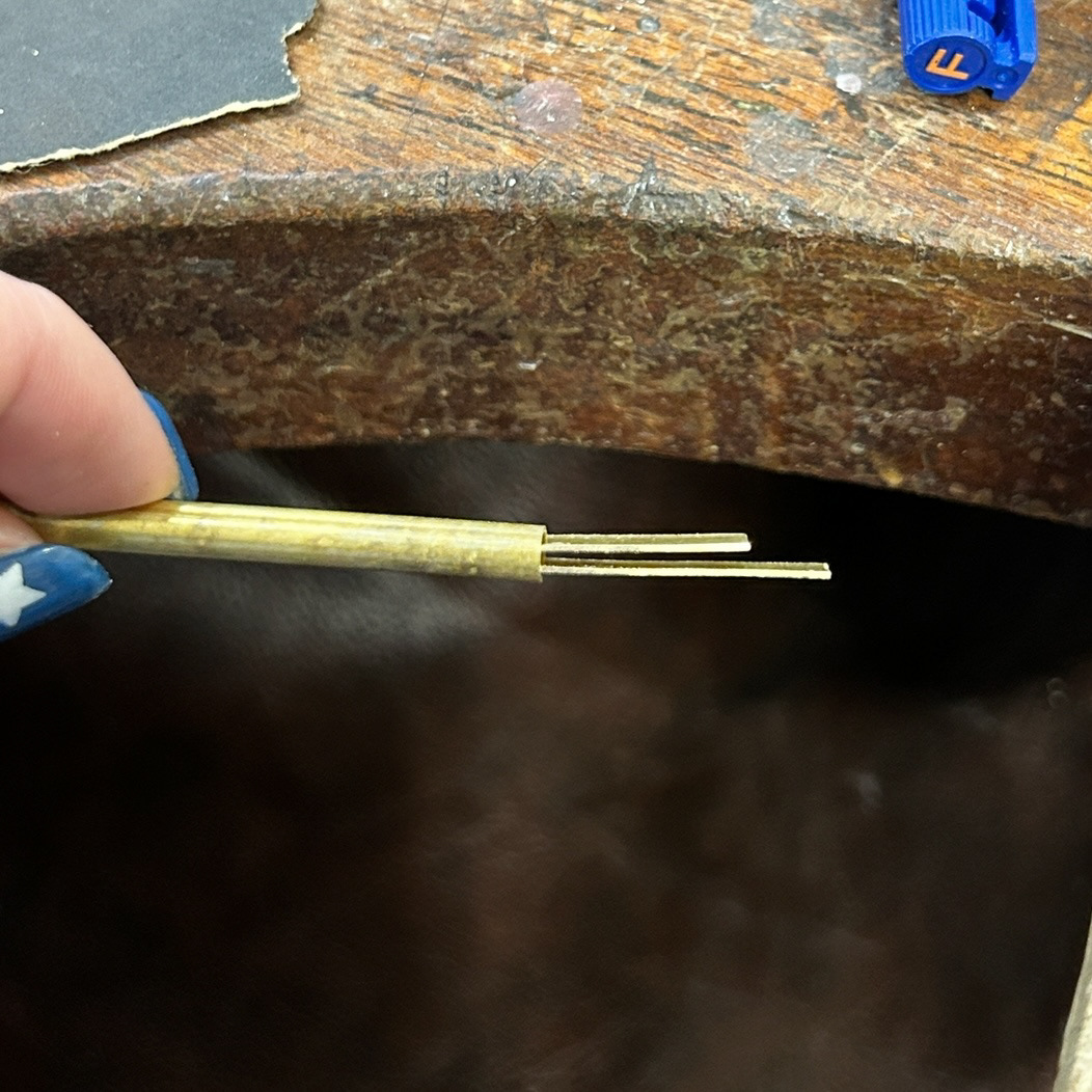
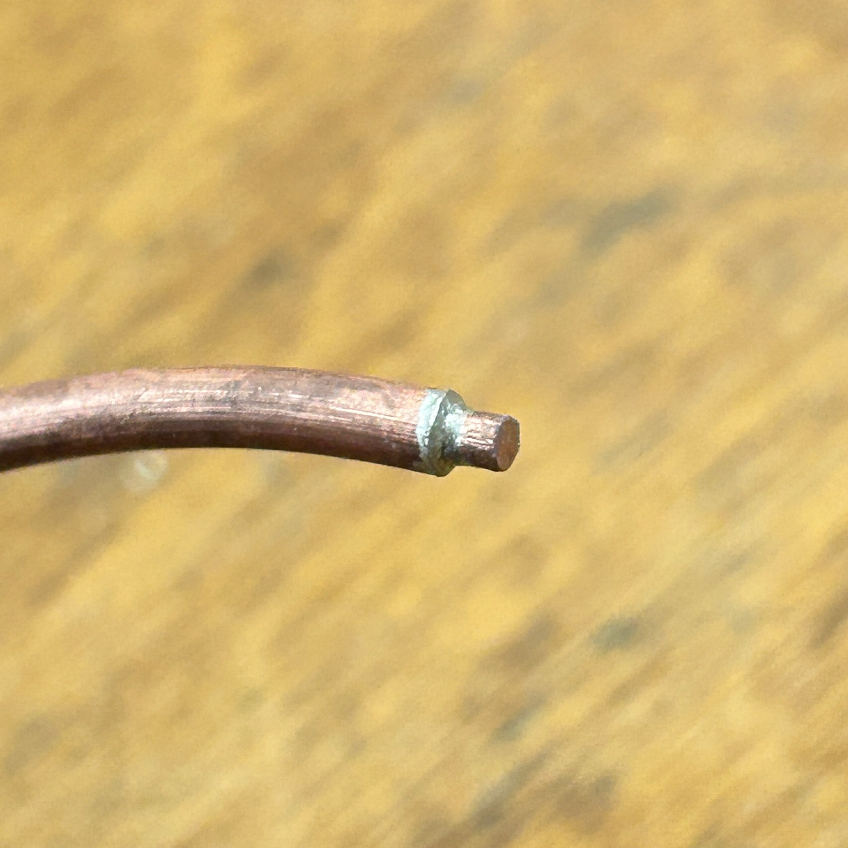
I began by annealing my metal and filing it to a point so that I could push it through the drawing plates and make it 0.1mm smaller.
After I had done this a few times, I was able to get the brass wire into the tube securely.
I then measured the thickness of the wire that I would be threading between the two pieces and drilled a hole 1mm larger. I threaded through the wire, tripped the excess and then hammered to rivet each side. While this mechanism is not as slick as I would like it to be, I feel that with some sanding and polishing, I can make the join between the wire and the tubing less noticeable.
Magnet Closure

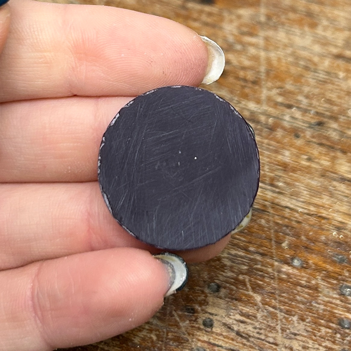
After looking back at the riveting sample, I realised that this was not the ideal design I wanted to use. I decided to test the magnet mechanism that Mark had suggested, as I realised that I would only need the smallest amount of glue to secure the magnets into place, and it would give the brooches a more contemporary look, while also being functional.
The magnets I planned to use were quite small, measuring 2mm in diameter and 1mm in height, making them relatively weak. To increase the stability, I decided to incorporate a small friction-fit mechanism alongside the magnets to keep them in place securely and improve the overall sturdiness of the brooch.
I first tested this mechanism using brass and copper. Unfortunately, this mechanism did not work as I had hoped. Even by combining the friction fit with the magnets, it was still not strong enough to hold the two halves together and secure the resin into place. I knew that I had two options at this point, use the riveting mechanism which would hold the two pieces into place but could look unrefined and lazy, or rethink the design and have an opening at the top where I would be able to move the metal slightly to slot the bacteria/resin into place. I decided to go for the latter as I believed that while it may not be a complex mechanism like I had hoped to do, it would be a better design choice than the riveting.
I did however use this prototype to test the soldering that I would be using for the prongs, which would hold the brooch mechanism on the back. I gently filed the edge of the copper wire to fit the profile of the wire and soldered.